
PDU14B15A1U - Power Strip V7 - Free user manual and instructions
Find the device manual for free PDU14B15A1U V7 in PDF.
| Brand | V7 |
| Model | PDU14B15A1U |
| Product Type | Rack-mount Power Strip (PDU) |
| Rack Format | 1U (horizontal or vertical mounting) |
| Dimensions (W x D x H) | 17.5 x 1.7 x 2.2 inches (44.5 x 4.3 x 5.6 cm) |
| Weight (estimated) | 1.5 kg |
| Power - Input Voltage | 100 ~ 125 V AC |
| Maximum Input Current | 15 A |
| Built-in Circuit Breaker | Yes, 15 A (resettable) |
| Input Plug Type | NEMA 5-15P (3-prong US plug) |
| Power Cord Length | 3 meters |
| Output Type (receptacles) | NEMA 5-15R (10 to 14 outlets depending on configuration) |
| Number of Outlets | 14 (NEMA 5-15R) |
| Electrical Protection | Thermal circuit breaker 15 A |
| Housing Material | Steel (aluminum on some models) |
| Mounting Options | Horizontal or vertical with included brackets, optional cable pass-through panel |
| Operating Temperature | 0 to 35 °C |
| Operating Humidity | 0 to 95% (non-condensing) |
| Maximum Altitude | 3000 m (operating) |
| Certifications | ETL (UL 1363), CSA C22.2, RoHS |
| Warranty | 3 years (limited) |
| Maintenance and Cleaning | Unplug before cleaning; use a dry cloth; do not use solvents |
| Spare Parts | Contact technical support for replacement parts (cord, circuit breaker) |
| Repairability | Resetable circuit breaker; other repairs by a professional |
Frequently Asked Questions - PDU14B15A1U V7
User questions about PDU14B15A1U V7
0 question about this device. Answer the ones you know or ask your own.
Ask a new question about this device
Download the instructions for your Power Strip in PDF format for free! Find your manual PDU14B15A1U - V7 and take your electronic device back in hand. On this page are published all the documents necessary for the use of your device. PDU14B15A1U by V7.
USER MANUAL PDU14B15A1U V7
USERMANUAL MANUEL DELL'UTILISATEUR
PDU
PDU14B15A0U
PDU14B15A1U

TABLE OF CONTENTS
1 Getting Started
Package Includes
2 Setup
Horizontal Rack Mounting (1U model only)
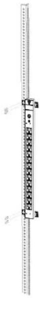
Vertical Rack Mounting (0U & 1U)
Keyhole Mounts (0U models only)
6 Plate for Vertical Rack Mounting (0U model only)
Cord Retention Tray Installation
Electrical Installation
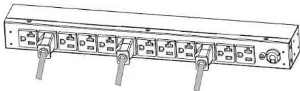
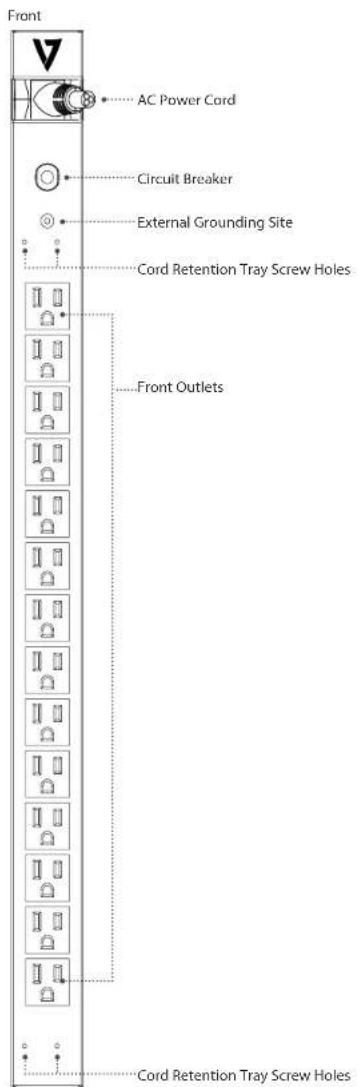
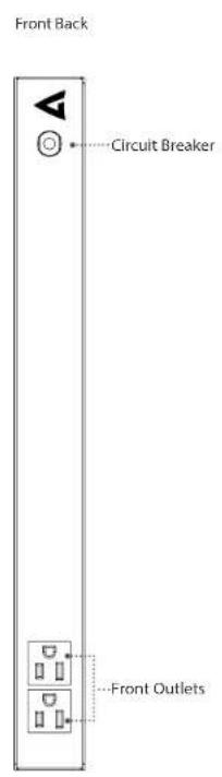
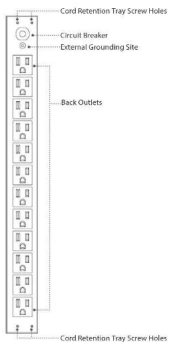
3 Product Features
4 Technical Specifications
Basic Series (1U)
Basic Series (OU)
5 Safety andWarnings

Package includes

BackFrom.
Included Accessories

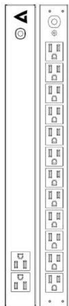
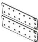
Horizontal Rack Mounting Brackets

Vertical Rack Mounting Brackets
6" Plate for Vertical Rack Mounting (for 0U models only)


Bracket Mounting Screws M4 x 6 (4 pcs)


Cord Retention Tray Mounting Screws M3 x 6 (4 pcs)
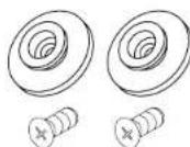
Keyhole Mounting Pegs (2 pcs) with Screws M4 x 6 (2 pcs) (For 0U models only)

Cable Ties (For Cord Retention Trays)

Grounding Screw M4×6 (1 pc)

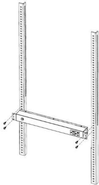
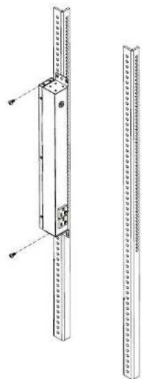
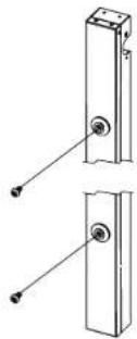
Horizontal Rack Mounting (1U model only) Vertical Rack Mounting (0U & 1U)
- Mount horizontal mounting brackets to PDU 1. Mount vertical mounting brackets to PDU

Install the bracket mounting (M4 x 6) screws in holes diagonal from each other.
- Mount PDU horizontally on Rack
Install the PDU using fasteners compatible with the rack.
- Mount PDU vertically on rack
Install the PDU using fasteners compatible with the rack.

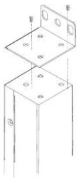
Keyhole Rack Mounting (OU model only)
- Keyhole mounting installation 1. Mount 6 plate to PDU
Attach the Keyhole Mounting Pegs to the PDU with the 2 supplied Bracket Mounting Screws (M4 X 6).
- Mount to Rack 2. Mount to Rack
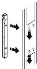
Align the Keyhole Mounts to the Keyhole Slots on the rack. Insert and slide down to lock firmly into place.
6" Plate for Vertical Rack Mounting (0U model only)
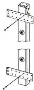
Install the PDU using fasteners compatible with the rack.

Cord Retention Tray Installation
(Optionai for both horizontal and vertical installation)
- Adjust the length of the Cord Retention Tray until the screw hole on the Tray and PDU are aligned.
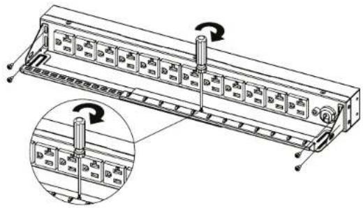
- Attach the Cord Retention Tray to the PDU with the 4 supplied Cord Retention Tray Mounting Screws (M3 X 6). Tighten the Cord Retention Tray with the screw on it.
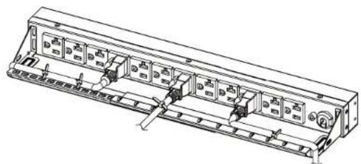
- Use the Cable Ties provided to fasten each power cord to the Cord Retention Tray.
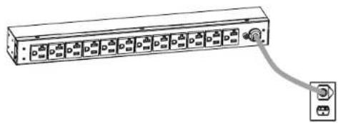
Electrical Installation
- Receptacle evaluation: Ensure that the plug type of your PDU unit (e.g. NEMA 5-15P, NEMA 5-20P, NEMA LS-30P) matches the wall receptacle type that you are using.

PDU must be plugged into a three-wire, grounded wall receptacle only. The wall receptacle must also be connected to an appropriate branch circuit/main with fuse or circuit breaker protection. Connection to any other type of wall receptacle may result in a shock hazard.
- Plug PDU into the wall outlet
- Attach equipment to PDU
Before attaching equipment, it is important to calculate the total load that you will be placing on the PDU. It is extremely important not to exceed the PDU's maximum current load (as outlined in the Specifications section). In order to determine your total load, simply add up the amperage of your devices and ensure that it does not exceed the unit's capacity.

PDU14B15A0UPDU14B15A1U
PDU14B15A0U
| Input | Voltage: 100 ~ 125 V |
| Max Current 15 A | |
| Circuit Breaker 15 A | |
| Plug Type: NEMA 5-15P | |
| Cord Length: 10 FT | |
| Output | Voltage: 100 ~ 125 V |
| Current: 15 A | |
| Outlet Type: NEMA 5-15R | |
| Dimensions (LxWxD) | 24 x 1.7 x 1.5 inches |
| Humidity | Operating 0 to 95% Non-condensing Non-Operating 0 to 95% Non-condensing |
| Altitude | Operating 0ft to 10,000ft Non-Operating 0ft to 50,000ft |
| Temperature | Operating 32F to 95F Non-Operating 5F to 113F |
| Compliance | ETL (followed UL 1363), CSA C22.2, RoHS |
| Warranty | 3 years |
PDU14B15A1U
| Input | Voltage: 100 ~ 125 V |
| Max Current 15 A | |
| Circuit Breaker 15 A | |
| Plug Type: NEMA 5-15P | |
| Cord Length: 15 FT | |
| Output | Voltage: 100 ~ 125 V |
| Current: 15 A | |
| Outlet Type: NEMA 5-15R | |
| Dimensions (LxWxD) | 17.5 x 1.7 x 2.2 inches |
| Humidity | Operating 0 to 95% Non-condensing Non-Operating 0 to 95% Non-condensing |
| Altitude | Operating 0ft to 10,000ft Non-Operating 0ft to 50,000ft |
| Temperature | Operating 32F to 95F Non-Operating 5F to 113F |
| Compliance | ETL (followed UL 1363), CSA C22.2, RoHS |
| Warranty | 3 years |
Safety Precautions Trouble Shooting
Read the following before installing or operating the Power Distribution Unit (PDU)
- CAUTION! Use ONLY the supplied hardware (including screws, pegs and cord retainer clips) to attach the mounting brackets. Using different hardware or improper installations may cause damage that is NOT covered by this warranty.
- The PDU must only be plugged into a three-wire, grounded outlet on a circuit protected by a fuse or circuit breaker. Connection to any other type of power outlet may result in a shock hazard.
- Do not use extension cords or adapters with this PDU.
- Never install a PDU, or associated wiring or equipment, during a lightning storm.
- Check that the power cord, plug, and socket are in good condition.
- CAUTION! To prevent the risk of fire or electric shock, this PDU should be installed in a temperature and humidity controlled indoor area free of conductive contaminants. Do not install this PDU where excessive moisture or heat is present.
| Problem Possible Cause Solution | ||
| PDU Outlets do not provide power to connected equipment | Open breaker, Loose power cord | Reset Breaker. Check if plug is completely connected. If the problem remains contact tech support. |
| Circuit breaker has tripped | Sustained overload, Excessive ambient or internal temperatures, Faulty breaker | Reset Breaker. If the problem remains, contact tech support. |
3 Year Warranty
-
-
-
-
-
-
-
-
-
-
-
-
-
-
-
-
-
-
-
-
-
-
-
-
-
-
-
-
-
-
-
-
-
-
-
-
-
-
-
-
-
-
-
-
-
-
-
-
-
-
-
-
-
-
-
-
-
-
-
-
-
-
-
-
-
-
-
-
-
-
-
-
-
-
-
-
-
-
-
-
-
-
-
-
-
-
-
-
-
- 90. The only products that are not included in the table are: (a) the product of the manufacturer, who has a written contract with the manufacturer; (b) the product of the manufacturer who has a written contract with the manufacturer; (c) the product of the manufacturer who has a written contract with the manufacturer; (d) the product of the manufacturer who has a written contract with the manufacturer; (e) the product of the manufacturer who has a written contract with the manufacturer; (f) the product of the manufacturer who has a written contract with the manufacturer; (g) the product of the manufacturer who has a written contract with the manufacturer; (h) the product of the manufacturer who has a written contract with the manufacturer; (i) the product of the manufacturer who has a written contract with the manufacturer; (j) the product of the manufacturer who has a written contract with the manufacturer; (k) the product of the manufacturer who has a written contract with the manufacturer; (l) the product of the manufacturer who has a written contract with the manufacturer; (m) the product of the manufacturer who has a written contract with the manufacturer; (n) the product of the manufacturer who has a written contract with the manufacturer; (o) the product of the manufacturer who has a written contract with the manufacturer; (p) the product of the manufacturer who has a written contract with the manufacturer; (q) the product of the manufacturer who has a written contract with the manufacturer; (r) the product of the manufacturer who has a written contract with the manufacturer; (s) the product of the manufacturer who has a written contract with the manufacturer; (t) the product of the manufacturer who has a written contract with the manufacturer; (u) the product of the manufacturer who has a written contract with the manufacturer; (v) the product of the manufacturer who has a written contract with the manufacturer; (w) the product of the manufacturer who has a written contract with the manufacturer; (x) the product of the manufacturer who has a written contract with the manufacturer; (y) the product of the manufacturer who has a written contract with the manufacturer; (z) the product of the manufacturer who has a written contract with the manufacturer; (aa) all other products except for those which are not included in this table. The only products that are not included in this table are: (a) the product of the manufacturer, who has a written contract with the manufacturer; (b) the product of the manufacturer who has a written contract with the manufacturer; (c) the product of the manufacturer who has a written contract with the manufacturer; (d) the product of the manufacturer who has a written contract with the manufacturer; (e) the product of the manufacturer who has a written contract with the manufacturer; (f) the product of the manufacturer who has an agreement with respect to its use or distribution; (g) any other commodity used as part of an industrial use or distribution; and (h) any other commodity used as part of an industrial use or distribution. The only products that are not included in this table are: (a) any other commodity used as part of an industrial use or distribution; (b) any other commodity used as part of an industrial use or distribution; and (c) any other commodity used as part of an industrial use or distribution. The only products that are not included in this table are: (a) any other commodity used as part of an industrial use or distribution; (b) any other commodity used as part of an industrial use or distribution; and (c) any other commodity used as part of an industrial use or distribution. The only products that are not included in this table are: (a) any other commodity used as part of an industrial-use distribution; (b) any other commodity used as part of an industrial-use distribution; and (c) any other commodity used as part of an industrial-use distribution. The only products that are not included in this table are: (a) any other commodity used as part of an industrial-use distribution; (b) any other commodity used as part of an industrial-use distribution; and (c) any other commodity used as part of an industrial-use distribution. The only products that are not included in this table are: (a) any other commodity used as part of an industrial-use distribution; (b) any other commodity used as part of an industrial use distribution; and (c) any other commodity used as part of an industrial use distribution. The only products that are not included in this table are: (a) any other commodity used as part of an industrial-use distribution; (b) any other commodity used as part of an industrial use distribution; and (c) any other commodity used as part of an industrial use distribution. The only products that are not included in this table are: (a) any other commodity used as part of an industrial-use distribution; (b) any other commodity used as part of an industrial-use distribution; and (c) any other commodity used as part of an industrial-use distribution. The only products that are not included in this table are: (a) any other commodity used as part of an industrial-use distribution; (b) any other commodity used as part of an industrial-Use distribution; and (c) any other commodity used as part of an industrial Use distribution. The only products that are not included in this table are: (a) any other commodity used as part of an industrial-use distribution; (b) any other commodity used as part of an industrial-use distribution; and (c) any other commodity used as part of an industrial-use distribution. The only products that are not included in this table are: (a) any other commodity used as part of an industrial-use distribution; (b) any other commodity used as part of an industrial Use distribution; and (c) any other commodity used as part of an industrial Use distribution. The only products that are not included in this table are: (a) any other commodity used as part of an industrial-use distribution; (b) any other commodity used as part of an industrial Use distribution; and (c) any other commodity used as part of an industrial Use distribution. The only products that are not included in this table are: (a) any other commodity used as part of an industrial-use distribution; (b) any other commodity used as part of an industrial-use distribution; and (c) any other commodity used as part of an industrial Use distribution. The only products that are not included in this table are: (a) any other commodity used as part of an industrial-use distribution; (b) any other commodity used as part of an industrial Use distribution; and (c) any other commodity used as part of an industrial Use distribution. The only products that are not included in this table are: (a) any other commodity used as part of an Industrial Use distribution; (b) any other commodity used as part of an Industrial Use distribution; and (c) any other commodity used as part of an Industrial Use distribution. The only products that are not included in this table are: (a) any other commodity used as part of an Industrial Use distribution; (b) any other commodity used as part of an Industrial Use distribution; and (c) any other commodity used as part of an Industrial Use distribution. The only products that are not included in this table are: (a) any other commodity used as part of an Industrial Use distribution; (b) any other commodity used as part of anIndustrial Use distribution; and (c) any other commodity used as part of an Industrial Use distribution. The only products that are not included in this table are: (a) any other commodity used as part of an Industrial Use distribution; (b) any other commodity used as part of an Industrial Use distribution; and (c) any other commodity used as part of an Industrial Use distribution. The only products that are not included in this table are: (a) any other commodity used as part ofan Industrial Use distribution;(b) any other commodity used aspartofan Industrial Usedistribution;(c) any other commodity used aspartofan Industrial Usedistribution;(d) any other commodity used aspartofan Industrial Usedistribution;(e) any other commodity used aspartofan Industrial Usedistribution;(f) any other commodity usedaspartofan Industrial Usedistribution;(g) any other commodity usedaspartofan Industrial Usedistribution;(h) anyothercommodityusedaspartofanIndustrialUsedistribution;(i)(ii)(iii)(iv)(v)(vi)(vii)(viii)(ix)(x)(xi)(xx)(xx)(xxii)(xxiii)(xxiv))
-
-
-
-
-
-
-
-
-
-
-
-
-
-
-
-
-
-
-
-
-
-
-
-
-
-
-
-
-
-
-
-
-
-
-
-
-
-
-
-
-
-
-
-
-
-
-
-
-
-
-
-
-
-
-
-
-
-
-
-
-
-
-
-
-
-
-
-
-
-
-
-
-
-
-
-
-
-
-
-
-
-
-
-
-
-
-
-
y t t t t t t t t t t t t t t t t t t t t t t t t t t t t t t t t t t t t t t t t t t t t t t t t t t t e
Tnss:Gnnne imaeke 1
Ingegner M. Vincenzo
Department of Mathematics, Sulls 103, Irfiello, CA 96512, USA
Cerant
Ingemirna,IPCarolina
Sa Swedish Court
Mssssua,CN,LLR441.Canza
Model/Modèle:
Date of purchase: Date d'achat:
www.V7-world.com
TABLE DES MATIÈRES
1 Demarrage
Contenu du paquet
2 Installation
V7p0y prrnne rnrnnn nnnn nnnn nnnn nnnn nnnn nnnn nnnn nnnn nnnn nnnn nnnn nnnn nnnn nnnn nnnn nnnn nnnn nnnn nnnn nnnn nnnn nnnn nnnn nnnn nnnn nnnn nnnn nnnn nnnn nnnn nnnn nnnn nnnn nannn nnnn nnnn nnnn nnnn nnnn nnnn nnnn nnnn nnnn nnnn nnnn nnnn nnnn nnnn nnnn nnnn nnnn nnnn nnnn nnnn nnnn nnnn nnnn nnnn nnnn nnnn nnnn nnnn nnnn nnnn nnnn nnnn nnn.
y t t t t t t t t t t t t t t t t t t t t t t t t t t t t t t t t t t t t t t t t t t t t t t t t t t t t
Singer Social
2
20841ke de Instruetioa
253021
BCSLLBMetropols344658117
Sant41 cmmn 002502587
Contac adriminatb6025 084726
Centre Logistique
2023年4月1日
Aeae de la Rontale
5916310mm
Agencssie-efnne
一、担保情况
21 me Nickel Faraday
78180Mar
N
24 boulevandesles
213155748000000
Modele:
Date d'achat

www.V7-world.com
- USERMANUAL MANUEL DELL'UTILISATEUR
- TABLE OF CONTENTS
- Getting Started
- Setup
- Product Features
- Technical Specifications
- Safety andWarnings
- Package includes
- Horizontal Rack Mounting (1U model only) Vertical Rack Mounting (0U & 1U)
- Keyhole Rack Mounting (OU model only)
- 6" Plate for Vertical Rack Mounting (0U model only)
- Cord Retention Tray Installation
- Electrical Installation
- Safety Precautions Trouble Shooting
- Year Warranty
- TABLE DES MATIÈRES
- Demarrage
- Installation
- Singer Social
- Centre Logistique
- Agencssie-efnne
Brand : V7
Model : PDU14B15A1U
Category : Power Strip