
AR403722 - Remote control GAGGENAU - Free user manual and instructions
Find the device manual for free AR403722 GAGGENAU in PDF.
| Product type | Remote control for range hood |
| Brand | Gaggenau |
| Model | AR403722 |
| Power supply | Via control cable (supplied) |
| Connection | Network via shielded Cat5 cable (min.) |
| Max. number of networked devices | 20 |
| Max. total network cable length | 40 m |
| Additional switching output | Yes, potential-free contact, 30 V/1 A max. |
| Connection for window contact | Yes (accessory AA 400 510) |
| Main functions | Control of ventilation (speeds), lighting, networking, window contact management |
| Safety | Complies with UL 507 and CAN/CSA C22.2 No. 113 |
| Maintenance | Clean with a soft, dry cloth |
| Spare parts and repairability | Accessories and parts available at www.gaggenau.com |
Frequently Asked Questions - AR403722 GAGGENAU
User questions about AR403722 GAGGENAU
0 question about this device. Answer the ones you know or ask your own.
Ask a new question about this device
Download the instructions for your Remote control in PDF format for free! Find your manual AR403722 - GAGGENAU and take your electronic device back in hand. On this page are published all the documents necessary for the use of your device. AR403722 by GAGGENAU.
USER MANUAL AR403722 GAGGENAU
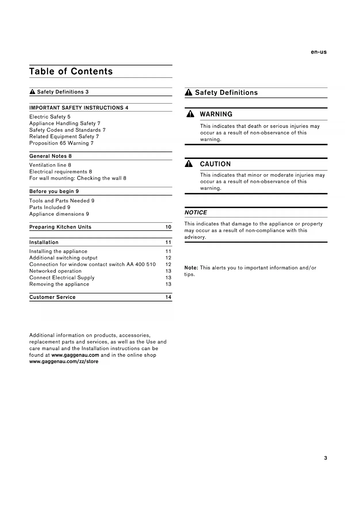
⚠ Safety Definitions 3
IMPORTANT SAFETY INSTRUCTIONS 4
Electric Safety 5
Appliance Handling Safety 7
Safety Codes and Standards 7
Related Equipment Safety 7
Proposition 65 Warning 7
General Notes 8
Ventilation line 8
Electrical requirements 8
For wall mounting: Checking the wall 8
Before you begin 9
Tools and Parts Needed 9
Parts Included 9
Appliance dimensions 9
| Preparing Kitchen Units | 10 |
| Installation | 11 |
Installing the appliance 11
Additional switching output 12
Connection for window contact switch AA 400 510 12
Networked operation 13
Connect Electrical Supply 13
Removing the appliance 13
| Customer Service | 14 |
Additional information on products, accessories, replacement parts and services, as well as the Use and care manual and the Installation instructions can be found at www.gaggenau.com and in the online shop www.gaggenau.com/zz/store
Safety Definitions
WARNING
This indicates that death or serious injuries may occur as a result of non-observance of this warning.
CAUTION
This indicates that minor or moderate injuries may occur as a result of non-observance of this warning.
NOTICE
This indicates that damage to the appliance or property may occur as a result of non-compliance with this advisory.
Note: This alerts you to important information and/or tips.

IMPORTANT SAFETY INSTRUCTIONS
READ AND SAVE THESE INSTRUCTIONS
INSTALLER: LEAVE THESE INSTRUCTIONS WITH THE APPLIANCE AFTER INSTALLATION IS COMPLETE.
IMPORTANT: SAVE THESE INSTRUCTIONS FOR THE LOCAL ELECTRICAL INSPECTOR'S USE.
Examine the appliance after unpacking it. In the event of transport damage, do not plug it in.

WARNING
If the information in this manual is not followed exactly, fire or shock may result causing property damage or personal injury.

WARNING
Do not repair, replace or remove any part of the appliance unless specifically recommended in the manuals. Improper installation, service or maintenance can cause injury or property damage. Refer to this manual for guidance. All other servicing should be done by an authorized service provider.

WARNING
WARNING - TO REDUCE THE RISK OF FIRE, ELECTRIC SHOCK, OR INJURY TO PERSONS, OBSERVE THE FOLLOWING:
- Installation work and electrical wiring must be done by qualified person(s) in accordance with all applicable codes and standards, including fire-rated construction.
- Sufficient air is needed for proper combustion and exhausting of gases through the flue (chimney) of fuel burning equipment to prevent back drafting. Follow the heating equipment manufacturer's guideline and safety standards such as those published by the National Fire Protection Association (NFPA), and the American Society for Heating, Refrigeration and Air Conditioning Engineers (ASHRAE), and the local code authorities.
- When cutting or drilling into wall or ceiling, do not damage electrical wiring and other hidden utilities.
- Ducted fans must always be vented to the outdoors.

IMPORTANT SAFETY INSTRUCTIONS
READ AND SAVE THESE INSTRUCTIONS

WARNING
The applicable regulations of the energy supply companies and the regional construction regulations must be observed when installing the hood.

WARNING
Risk of fire!
Operating several gas burners at the same time gives rise to a great deal of heat. The ventilation appliance may become damaged or catch fire. The ventilation appliance must only be combined with gas burners that do not exceed the maximum total output of 61,000 BTU/hr (18 kW). If 41,000 BTU/hr (12 kW) is exceeded, the local regulations concerning room ventilation, room size, and combination with ventilation devices in exhaust and recirculating operation must be followed.

WARNING
To reduce risk of fire and to properly exhaust air, be sure to duct air outside. Do not vent exhaust air into spaces within walls, ceilings, attics, crawl spaces or garages.

WARNING
To reduce the risk of fire, use only metal ductwork.

CAUTION
For general ventilating use only. Do not use to exhaust hazardous or explosive materials and vapors.
This appliance is intended for normal family household use only. It is not approved for outdoor use. See the Statement of Limited Product Warranty. If you have any questions, contact the manufacturer.
Electric Safety
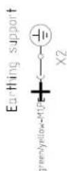
GROUNDING INSTRUCTIONS
This appliance must be grounded. In the event of an electrical short circuit, grounding reduces the risk of electric shock by providing an escape wire for the electric current.

WARNING
RISK OF ELECTRIC SHOCK!
Improper grounding can result in a risk of electric shock. Consult a qualified electrician if the grounding instructions are not completely understood, or if doubt exists as to whether the appliance is properly grounded.

IMPORTANT SAFETY INSTRUCTIONS
READ AND SAVE THESE INSTRUCTIONS

WARNING
Risk of electrical shock or fire!
Frame grounded to neutral through a ground strap. Grounding through the neutral conductor is prohibited for new branch-circuit installations (1996 NEC), mobile homes, and recreational vehicles, or in an area where local codes prohibit grounding through the neutral conductor.
For installations where grounding through the neutral conductor is prohibited,
- disconnect the link from the neutral,
- use grounding terminal or lead to ground unit,
- connect neutral terminal to lead branch circuit neutral in usual manner (when the appliance is to be connected by means of a cord kit, use a UL listed 4-conductor cord for this purpose).

WARNING
Before you plug in an electrical cord or turn on power supply, make sure all controls are in the OFF position.
If required by the National Electrical Code (or Canadian Electrical Code), this appliance must be installed on a separate branch circuit.

WARNING
To reduce the risk of fire or electric shock, do not use this fan with any solid-state speed control device.
Installer – show the owner the location of the circuit breaker or fuse. Mark it for easy reference.
Before installing, turn power OFF at the service panel. Lock service panel to prevent power from being turned ON accidentally.

WARNING
TO REDUCE THE RISK OF FIRE, ELECTRIC SHOCK, OR INJURY TO PERSONS, OBSERVE THE FOLLOWING:
- Use this unit only in the manner intended by the manufacturer. If you have questions, contact the manufacturer.
- Before servicing or cleaning unit, switch power off at service panel and lock the service disconnecting means to prevent power from being switched on accidentally.
When the service disconnecting means cannot be locked, securely fasten a prominent warning device, such as a tag, to the service panel.

IMPORTANT SAFETY INSTRUCTIONS
READ AND SAVE THESE INSTRUCTIONS
Be sure your appliance is properly installed and grounded by a qualified technician. Installation, electrical connections and grounding must comply with all applicable codes.

WARNING
Risk of electric shock!
Parts inside the appliance can have sharp edges. The connection cable can be damaged. Do not bend or pinch connection cables during installation.
Appliance Handling Safety

Hidden surfaces may have sharp edges. Use caution when reaching behind or under appliance.
Safety Codes and Standards
This appliance complies with the latest version of one or more of the following standards:
• UL 507 - Electric Fans
• CAN/CSA C22.2 No. 113 - Fans and Ventilators
It is the responsibility of the installer to determine if additional requirements and/or standards apply to specific installations.
Related Equipment Safety
Remove all tape and packaging before using the appliance. Destroy the packaging after unpacking the appliance. Never allow children to play with packaging material.
The appliance should only be used if installed by a qualified technician in accordance with these installation instructions. The manufacturer is not responsible for any damage resulting from incorrect installation.
Never modify or alter the construction of the appliance. For example, do not remove leveling legs, panels, wire covers or anti-tip brackets/screws.
Proposition 65 Warning:
This product may contain a chemical known to the State of California, which can cause cancer or reproductive harm. Therefore, the packaging of your product may bear the following label as required by California:
STATE OF CALIFORNIA PROPOSITION 65 WARNING:

WARNING
Cancer and Reproductive Harm - www.P65Warnings.ca.gov
General Notes
Ventilation line
Note: The appliance manufacturer does not assume any warranty for complaints attributable to the duct section.
- The appliance achieves its optimum performance by means of a short, straight exhaust air duct and as large a duct diameter as possible.
- As a result of long rough exhaust air ducts, many duct bends or duct diameters that are smaller than 6" (150 mm), the optimum extraction performance is not achieved and fan noise is increased.
- The ducts or hoses for laying the exhaust air line must be made of non-combustible material.
Electrical requirements
This appliance must be properly installed and grounded by a qualified technician in accordance with the National Electrical Code ANSI/ NFPA 70 (latest edition) and local electrical code requirements. IN CANADA: Electrical installation must be in accordance with the current CSA C22.1 Canadian Electrical Codes Part1 and/or local codes.
The range must be connected to the proper electrical voltage and frequency as specified on the rating plate.
For wall mounting: Checking the wall
- The wall must be level, vertical and adequately load-bearing.
- Use suitable fasteners depending on the type of construction (e.g. massive brickwork, drywall, porous concrete, Poroton wall tiles).
- The depth of the bore holes must be the same length as the screws. The wall plugs must have a secure grip.
- The maximum weight of the fan module is approx. 20 lb (9 kg).
Before you begin
Tools and Parts Needed
- Screwdriver Torx T20
- Pencil
- Drill with 14'' (6 mm) bit
• Phillips head screwdriver
• Jigsaw - Tape Measure
- Tin snips
Note: Additional materials may be necessary for installation in solid surface countertops. Contact the countertop manufacturer.
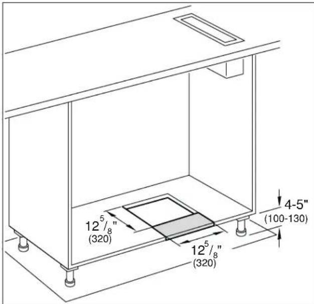
Parts Included
natural_image
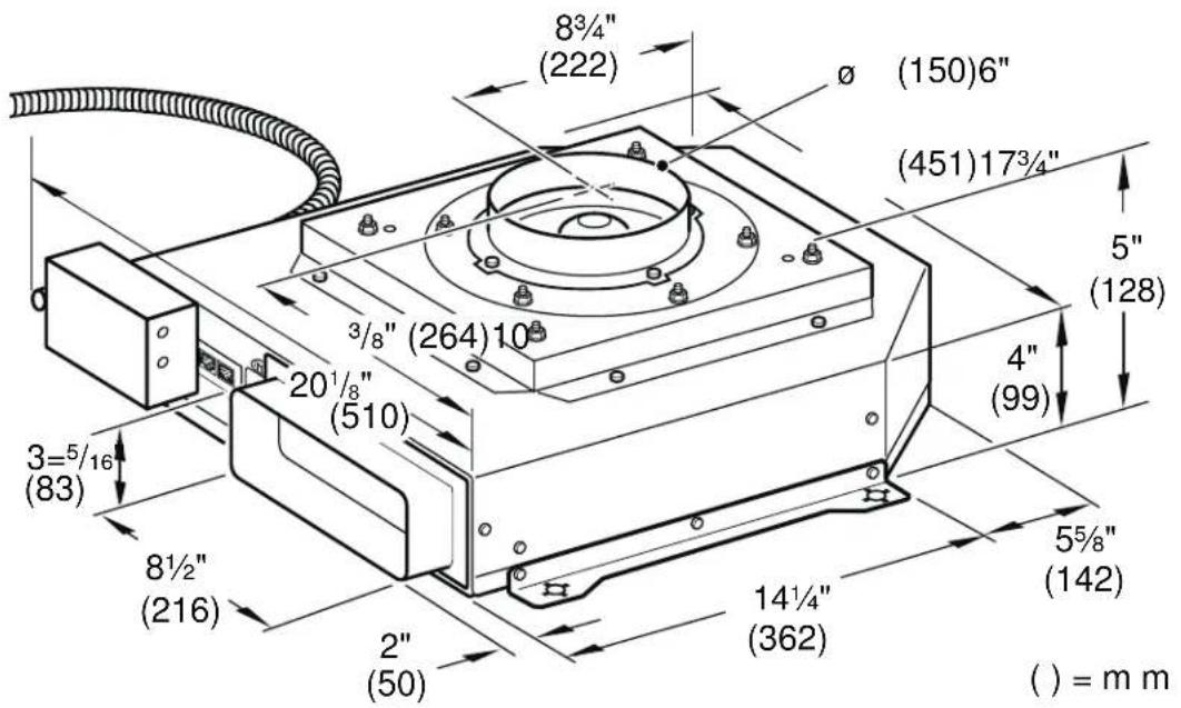
Technical line drawing of a mechanical assembly with components like a flange, coiled cable, and bracket (no text or labels)Appliance dimensions

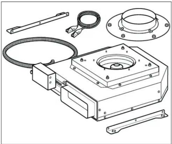
Preparing Kitchen Units
The stability of the fitted unit must also be guaranteed after the cut-out work.
Make the cut-out in the bottom plate in accordance with the installation drawing.
After the cut-out work is complete, remove the shavings.
Notes
- The position of the cut-out can be varied according to the local conditions.
- The distance between the feet must be at least 20½" (520 mm).
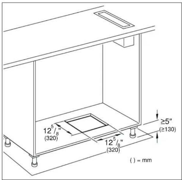
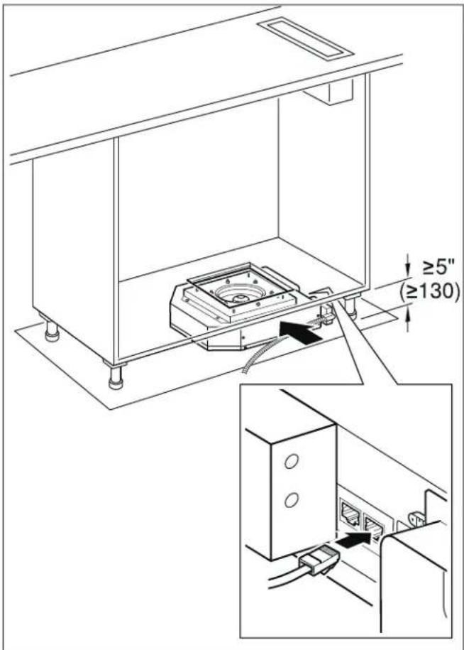
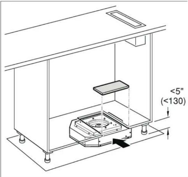
Note: For a toe-kick height of less than 5" (130 mm), an opening towards the front must be created. This part of the bottom plate can be reinserted after installation.
Installation
Installing the appliance
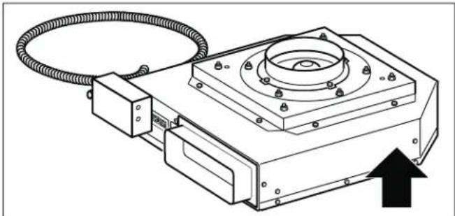
- Push the appliance under the cabinet.
Do not bend or pinch the power cable, or route it over sharp edges.
Note: The appliances have rubber feet, fastening not required.
- Alternative: Mount the supplied bracket to the side of the appliance and then secure the appliance to the back wall using 4 screws.
Note: Align the appliance horizontally.
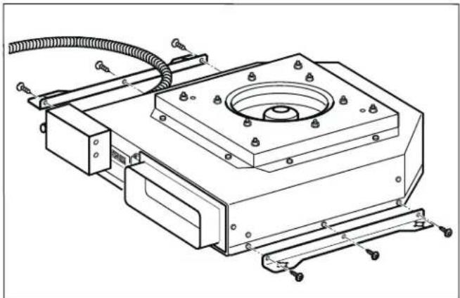
natural_image
Technical line drawing of a mechanical assembly with mounting bracket and wiring (no text or symbols)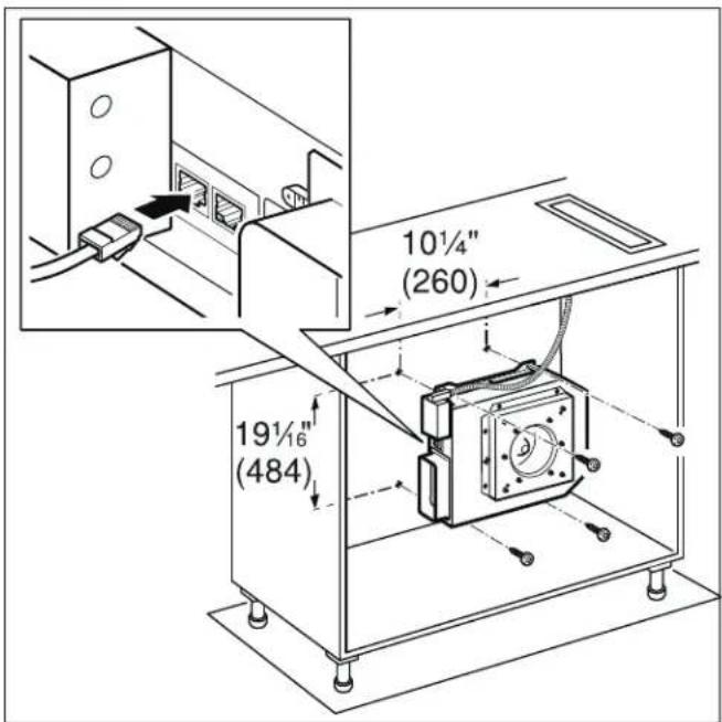
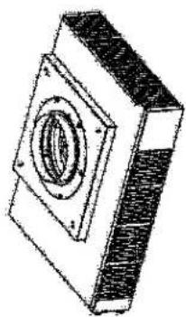
- Mount the connecting piece to the appliance. Alternatively, connect an air collector box (special accessory).
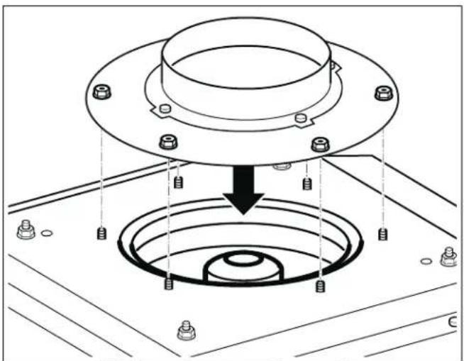
natural_image
Technical diagram of a mechanical assembly with a flange and concentric rings, showing bolted components (no text or labels)- Secure the exhaust-air duct to the connecting piece and seal appropriately.
Notes
- In combination with gas cooktops, aluminum duct must be used.
- If an aluminum duct is used, smooth the connection area beforehand.
Connecting the network cable
- Use the control cable to connect the remote fan unit and the fan. The plug must snap into place.
- Verify that the appliance works. If the appliance does not work, check that the control cable is correctly positioned.
Note: The X1 and X2 connection sockets are identical.
Additional switching output

WARNING
Work must only be carried out on the additional switching output by a qualified electrician in accordance with the country-specific requirements and standards.
The appliance has an additional switching output X16 (potential-free contact) that can be used to connect other appliances, such as a ventilation system that is available at the installation site. The contact is closed when the blower is switched on, and is opened when the blower is switched off.
The switching output is located under a cover. Maximum switching power 30 V/1 A (AC/DC). The signal that is connected to the contact must correspond to class of protection 3.
Connection for window contact switch AA 400 510
Work on the connection for the window contact switch must only be carried out by a qualified electrician in accordance with the requirements and standards of the country in which in the appliance is being used.
The appliance has a connection (X17) for a window contact switch. The window contact switch can be flush mounted or surface mounted. You will receive the window contact switch AA 400 510 separately as an accessory. Please observe the installation instructions enclosed with the window contact switch.
If a window contact switch is connected, the extractor hood's ventilation system will only work with the window open. The lighting will work even if the window is closed.
If you switch on the ventilation system with the window closed, the button for the ventilation setting you have selected will flash, and the ventilation system will not switch on.
If you close the window while the ventilation system is on, the appliance will switch the ventilation system off within 5 seconds. The button for the ventilation setting you have selected will flash.
The entire ventilation network and window contact switch must be assessed by a master chimney sweep.
Networked operation
Several appliances can be networked together. The light and blower on each of the appliances are operated synchronously.
Connect the appliances in series via the connector sockets X1 and X2 (equal value). The sequence of the networking does not have any effect. If the enclosed network cables are too short, use a commercially available network cable (min. Cat. 5, shielded).
Maximum number of networked appliances: 20. Total length of all of the network cables: 131 feet (40 m). During the initial installation, a qualified electrician must check that the system functions correctly.
If one of the networked appliances fails (power interruption, network cable disconnected), this leads to the blower function being blocked for the entire system. All of the buttons on the appliance flash.
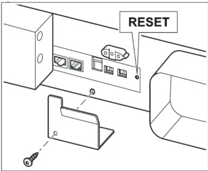
When changing the configuration, the system must be re-initialized:
- Unscrew the cover plate.
- Press and hold the reset button until both LEDs light up continuously (approx. 5 seconds). Then release the button within 5 seconds.
- Screw on the cover plate.
- After initialization, have a qualified electrician check that the system functions correctly.
Connect Electrical Supply

WARNING
Before you connect an electrical cord for permanent connection or turn on power supply, make sure all controls are in the OFF position.

WARNING
Risk of electric shock!
Parts inside the appliance can have sharp edges. The connection cable can be damaged. Do not bend or pinch connection cables during installation.
Attach flexible conduit to the junction box. The junction box must be accessible after installation.
To facilitate serviceability, the flex conduit should be routed to allow for temporary removal of the appliance.
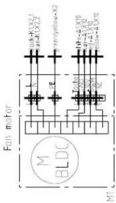
Connect the wires from the appliance conduit to the junction box supply wires in proper phase:
- black (L)
- white (neutral)
- green (ground)
Check the Installation

WARNING
Before you connect an electrical cord for permanent connection or turn on power supply, make sure all controls are in the OFF position.
Switch on the circuit breaker.
Verify that elements function properly.
Removing the appliance
Disconnect the appliance from the power supply. Remove the control cable. Undo the exhaust connections. Pull out the appliance.
Customer Service
If your appliance needs repairs, our customer service is there for you. We work hard to help solve problems quickly and without unnecessary service calls, getting your appliance back up and running correctly in the least amount of time possible.
When you call, please indicate the product number (E-Nr.) and serial number (FD-Nr.) so that we can support you in a qualified manner.
You will find the type plate with these numbers at the front and side of the appliance.
natural_image
Technical line drawing of a mechanical device with coiled cable and mounting bracket (no text or symbols)To avoid having to search for a long time when you need it, you can enter your appliance data and the customer support telephone number here.
E-Nr. FD-Nr.
Customer Service
Please read the Instruction Manuals provided with your appliance. Failure to do so may result in an error in using the appliance. This could result in a service call that instead of fixing a mechanical issue is only needed for customer education. Such calls are not covered by the appliance warranty.
Please find the contact data of all countries in the enclosed customer service list.
To book a service visit and product advice
USA 877 442 4436
toll-free
CANADA 877 442 4436
toll-free
Table des matières
www.P65Warnings.ca.gov
natural_image
Technical line drawing of a mechanical assembly with components like a flange, coiled cable, and tool holder (no text or labels)Cotes de l'appareil
natural_image
Technical line drawing of a mechanical assembly with mounting flange and wiring (no text or symbols)
natural_image
Technical diagram of a mechanical assembly with a flange and concentric rings, showing bolted components (no text or labels)natural_image
Technical line drawing of a mechanical assembly with components like a flange, coiled cable, and bracket (no text or labels)natural_image
Technical line drawing of a mechanical assembly with mounting flange and wiring (no text or symbols)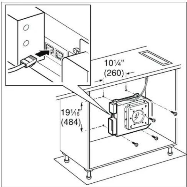
natural_image
Technical diagram of a mechanical assembly with mounting holes and a central circular component (no text or symbols)natural_image
Technical line drawing of a mechanical device with coiled cable and mounting bracket (no text or symbols)natural_image
Technical line drawing of a mechanical housing component (no text or symbols)AR403-122 220-240V - 50/60Hz AR403-722 120V - 50/60Hz
natural_image
Technical line drawing of a mechanical component with a square base and central circular feature (no text or symbols)AR413-122 220-240V - 50/60Hz AR413-722 120V - 50/60Hz
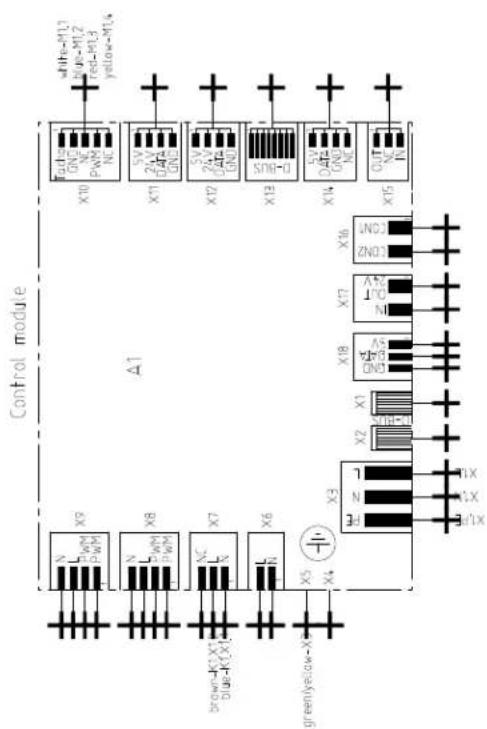
flowchart
graph TD
    A["Input Signal X9"] --> B["Channel 1"]
    C["Input Signal X8"] --> D["Channel 2"]
    E["Input Signal X7"] --> F["Channel 3"]
    G["Input Signal X6"] --> H["Channel 4"]
    I["Input Signal X5"] --> J["Channel 5"]
    K["Input Signal X4"] --> L["Channel 6"]
    M["Control Module Δ1"] --> N["Output Module"]
    N --> O["Output Signal X10"]
    N --> P["Output Signal X11"]
    N --> Q["Output Signal X12"]
    N --> R["Output Signal X13"]
    N --> S["Output Signal X14"]
    N --> T["Output Signal X15"]
    style A fill:#f9f,stroke:#333
    style C fill:#f9f,stroke:#333
    style E fill:#f9f,stroke:#333
    style G fill:#f9f,stroke:#333
    style K fill:#f9f,stroke:#333
    style M fill:#f9f,stroke:#333
    style N fill:#ccf,stroke:#333
    style O fill:#ccf,stroke:#333
    style P fill:#ccf,stroke:#333
    style Q fill:#ccf,stroke:#333
    style R fill:#ccf,stroke:#333
    style S fill:#ccf,stroke:#333

Gaggenau
BSH Home Appliance Corporation
1901 Main Street, Suite 600
Irvine, CA 92614
1-877-442-4436
www.gaggenau.com/us
© 2020 BSH Home Appliances
- ⚠ Safety Definitions 3
- IMPORTANT SAFETY INSTRUCTIONS 4
- General Notes 8
- Before you begin 9
- Safety Definitions
- WARNING
- CAUTION
- NOTICE
- IMPORTANT SAFETY INSTRUCTIONS
- READ AND SAVE THESE INSTRUCTIONS
- Electric Safety
- GROUNDING INSTRUCTIONS
- Appliance Handling Safety
- Safety Codes and Standards
- Related Equipment Safety
- Proposition 65 Warning:
- General Notes
- Ventilation line
- Electrical requirements
- For wall mounting: Checking the wall
- Before you begin
- Tools and Parts Needed
- Preparing Kitchen Units
- Notes
- Installation
- Installing the appliance
- Connecting the network cable
- Additional switching output
- Connection for window contact switch AA 400 510
- Networked operation
- Connect Electrical Supply
- Check the Installation
- Removing the appliance
- Customer Service
- Table des matières
Brand : GAGGENAU
Model : AR403722
Category : Remote control