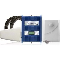
Pro 70 Plus - TV signal amplifier Wilson - Free user manual and instructions
Find the device manual for free Pro 70 Plus Wilson in PDF.


User questions about Pro 70 Plus Wilson
0 question about this device. Answer the ones you know or ask your own.
Ask a new question about this device
Download the instructions for your TV signal amplifier in PDF format for free! Find your manual Pro 70 Plus - Wilson and take your electronic device back in hand. On this page are published all the documents necessary for the use of your device. Pro 70 Plus by Wilson.
USER MANUAL Pro 70 Plus Wilson
Cellular Signal Boosters
Contents:
How Cellular Boosters Work .... 1
Install Overview 1
Kit Options....2
Installation Diagram 3 & 4
Outside Antenna Installation 5
Installing the Inside Panel Antenna(s) 7
Installing The Signal Booster 7
Finding The Strongest Signal 8
Post Install Setup / LCD Screen 9
Warnings and Recommendations 13
Warranty 16
Specifications .... Back
Appearance of device and accessories may vary.
Note: This manual contains important safety and operating information. Please read and follow the instructions in this manual. Failure to do so could result in damage to your Signal Booster.
How a Cellular Booster Improves Indoor Signals
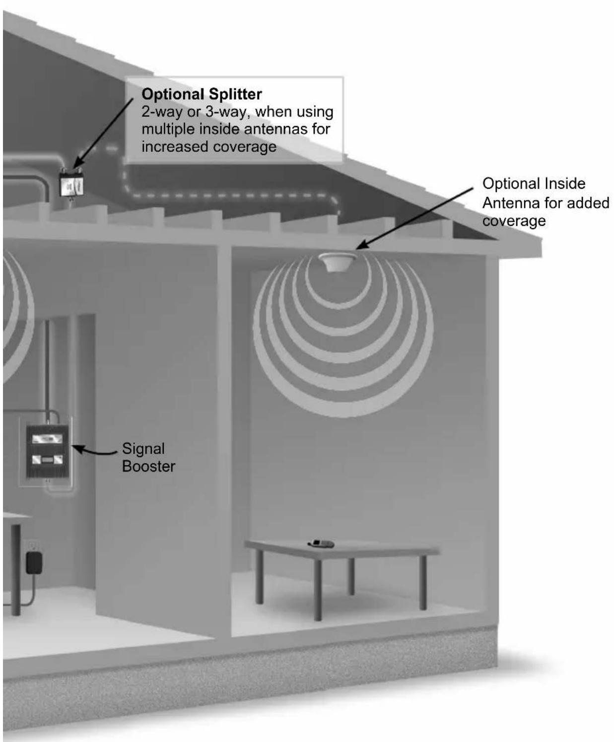
Wilson cellular signal booster systems work as follows: an outdoor antenna placed on a building where some cell signal is present, (ideally on a roof or pole), receives and sends that weak signal via coax cable (like used in satellite TV installs) to a signal booster located indoors. That weak signal is amplified by the booster and delivered via coax cable to an inside antenna(s) which rebroadcasts the amplified signal within one or several areas where improved signal is required. Signals from indoor cell device(s) are likewise picked up by the inside antenna(s), amplified by the signal booster and transmitted back to the cell tower via the outside antenna. The improved signals result in reliable cellular connections for indoor users.
About Gain and Improved Signal Area
The less signal strength at the outside antenna's location and/or the greater the coverage need, the more gain will be required. Conversely, the more signal present outside, the greater the inside coverage area will be. Proper aiming of the outside antenna towards the source of the cell signal is also important. The gains of the outside and inside antenna, though reduced by losses from coax cable lengths, also affect area of improved coverage. Placement of the inside antenna is also a factor as they have directional characteristics. Inside wall materials will also affect indoor coverage area.
Another important factor affecting coverage area is inadequate isolation between outside and inside antenna(s). Wilson boosters are designed to reduce their internal gain in order to prevent any feedback “oscillations” which if unchecked, could affect nearby cell site operation. The LCD status display on the booster is used to determine if a booster is operating at optimal gain for each cellular band. Optimal gain can be achieved by increasing antenna separation, i.e. isolation, until the max gain is indicated. If attainable separation is limited by a building’s layout, gain will suffer. A nearby cell site, even if not providing service to a user, can also cause the booster’s automatic network protection circuitry to reduce gain or even turn off one or more of the booster’s bands so as to prevent signal overload to the nearby site. The display on the booster can also be used to determine if this condition is taking place. Refer to pages 9-11 for explanation of the booster status display.
Install Overview
Refer to Installation Diagram on page 3 & 4. Contact Wilson Electronics Technical Support Team with any questions at 866-839-9361.
- Select a location on the roof or outside of the building to install the outside antenna. Refer to pages 3 & 5.
- Select a location to install the Signal Booster that is away from excessive heat, direct sunlight or moisture, and has adequate ventilation. Airtight enclosures are not recommended. Booster should be as close to the outside antenna as possible in order to minimize losses from cable length to outside antenna.
- Connect the cable from the outside antenna to the signal booster's "outside antenna"
connector. Refer to page 6 for more information on running cable. Lightning Surge Protection is recommended for all in-building installations. Refer to pages 3 & 6.
- Select a location for the inside antenna. Try to choose a position in the center of the area needing improved signal. Keep in mind that proper inside antenna to outside antenna isolation is necessary for the system to function properly. This may require as much as 50 to 75 feet of horizontal separation from the outside antenna. Vertical separation also helps increase isolation. Alternate means of isolation are possible. If physical separation is not possible, please contact Wilson Electronics Tech Support at 866-839-9361 for suggestions on alternate methods to achieve isolation.
- Connect the cable from the inside antenna to the signal booster's "inside antenna" connector. Refer to page 6 for more information on running cable. Keep cable runs as short as possible to reduce signal loss in the system.
- Before powering up the signal booster, verify that both the outside antenna and the inside antenna are connected correctly, and check that all connections are tight. Note: Be careful when plugging the connectors in so as not to bend the center pins on the connectors.
- Power on the signal booster by plugging in the included power supply. If the lights are not green, please refer to pages 10-11.
Multiple Kit Options Available
Note: Kits may contain different accessories
To purchase Expansion Kits call Wilson Electronics Sales Department at: 888-503-5329
463127 Kit
Pro 70 Plus
Wide Band Directional Antenna 75' LMR 400
Wide Band Panel Antenna
60' LMR 400
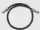
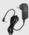
2' LMR 400 Lightning Surge
Power Supply
12V/3A

Protector
463227 Kit
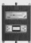
Pro 70 Plus
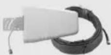
Wide Band Directional Antenna 75' LMR 400
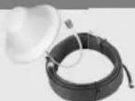
4G Dome Ceiling Antenna
60' LMR400 Cable
2' LMR 400 LightningCSDge
Power Supply
12V/3A

Protector
463327 Kit
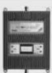
Pro 70 Plus
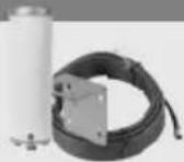
4G Omni Plus
Antenna 75' LMR400
Cable
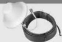
4G Dome Ceiling Antenna
60' LMR400 Cable
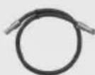
2' LMR 400 Lightning
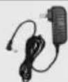
Power Supply
12V/3A

Protector
Installation Diagram
Note: A Wilson Lightning Surge Protector (859902) is recommended for all building installations. Make sure the protector is installed outside the building at point of entry connected to a suitable ground and in line between the Outside Antenna and the Signal Booster.
Outside Antenna
(Wide Band Directional Antenna shown)
Spacing Critical
Inside Antenna
Inside Antenna
Preferred Method: Place the Inside Antenna in the ceiling facing down for the best coverage.
Power Supply
Surge Protector Power Strip
text_image
Optional Splitter 2-way or 3-way, when using multiple inside antennas for increased coverage Optional Inside Antenna for added coverage Signal BoosterSelecting a Location for the Outside Antenna

text_image
Cell Tower Wide Band AntennaThe outside antenna must be mounted at a location outside of the home or building, where the strongest cell signal is present. This can be accomplished by using the Wilson Signal Meter. Alternatively, a cell phone in test mode can be used for finding the area around the building with the strongest signal.
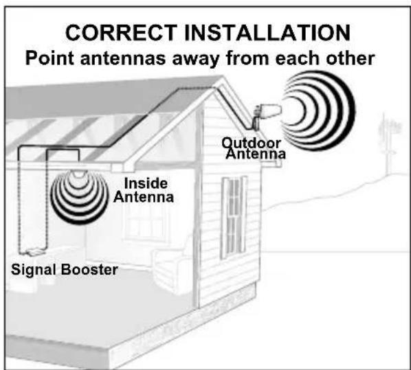
Mount the outside antenna as high as possible facing towards the suspected location of the cell tower and pointing away from the expected location of the inside antenna(s).
Outside Antenna Installation
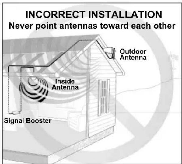
The antenna should be mounted as shown in Figure 1. The mounting bracket, included with antenna, is adjustable and will accommodate pipe diameters from 1.25 inches to 2 inches (pipe sold separately #901117). Mount the antenna so that there is at least 3 feet of clearance in all directions around it. Make sure the antenna is not pointing across your own roof or at the inside antenna as this will cause the cell site protection circuitry to shut down the signal booster.
text_image
CORRECT INSTALLATION Point antennas away from each other Outdoor Antenna Inside Antenna Signal BoosterFigure 1
text_image
INCORRECT INSTALLATION Never point antennas toward each other Outdoor Antenna Inside Antenna Signal BoosterFigure 2
Installing Lightning Protection

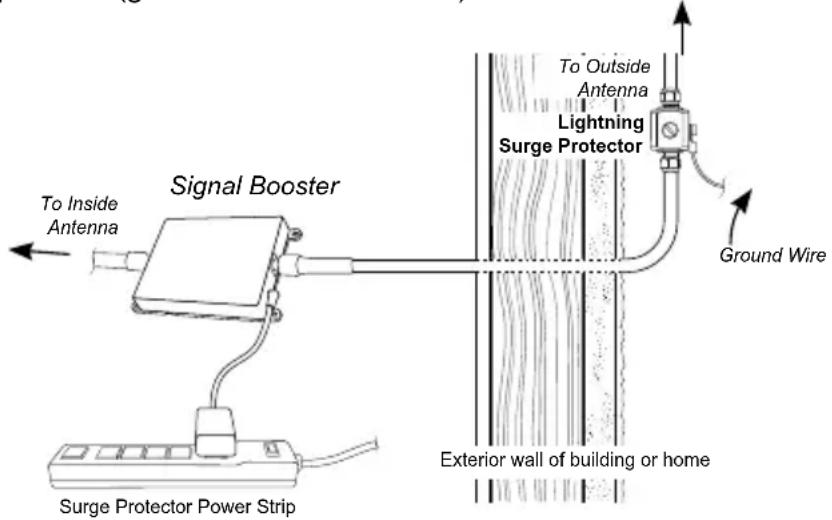
Warning: Lightning protection is recommended for all installations (#859902-50 Ohm, shown below). Take extreme care to ensure that neither you nor the antenna comes near any electric power lines.
Install the Lightning Surge Protector (LSP) outside, in line with the coax cable from the outside antenna, near where the coax cable from the outside antenna will enter the building. Connect the Outside antenna cable to one of the connectors of the surge protector. Connect the other connector on the LSP to the cable entering the building. Ensure the LSP is properly grounded as close to the LSP as possible (ground wire not included).
text_image
Signal Booster To Inside Antenna Surge Protector Power Strip To Outside Antenna Lightning Surge Protector Ground Wire Exterior wall of building or homeRunning Outside Antenna Cable
If you are mounting the outside antenna to the outside wall of your home or building, the simplest way is to run the cable on the outside of the wall and attach it to the exterior of your home or office. Then drill a hole through the wall where you want the cable to appear on the inside of the building. Before drilling, make sure that there are no electrical outlets, sewer or water pipes, or electrical wiring in the wall that you are about to drill through as this could potentially harm you or damage the building. Note: Existing TV cables already being used for another purpose can not be shared with the cell booster installation.
After drilling the required hole, run the cable through and seal it with cable bushings or a silicone-type sealant to enclose the hole that you have created. In some instances, it may be possible to run the cable up into the fascia of the attic overhang. In this circumstance, the cable will be accessible in the attic for further routing.
Installing the Inside Panel Antenna(s)
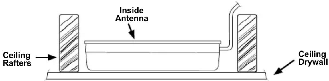
Select a location for the inside antenna, preferably in the center of where the signal needs to be amplified. A minimum separation distance of 20 vertical feet and or 50 horizontal feet between the inside and outside antenna(s) may be necessary in order to achieve full booster gain and therefore maximum indoor coverage. If the amplifier can not be set to maximum gain as explained on page 10, you may need as much as 75 feet of horizontal separation, or mechanical isolation, between inside and outside antennas. Refer to installation diagram on pages 3 & 4.
text_image
Inside Antenna Ceiling Rafters Ceiling DrywallSome installations requiring signal improvement in far areas of larger homes or structures may require multiple inside antennas and splitter(s). For example if signal is improved in most areas of a structure, but yet there is weak signal In another area, the signal from the booster can be split to two or more separate indoor antennas by using a splitter (sold separately). Refer to the configuration on pages 3 & 4.
natural_image
Abstract grayscale image with a faint circular shape and curved lines, no text or symbols present.Additional Inside Panel Antenna w/ cable sold separately
Multiple mounting options available
For additional antenna options see pages 14 & 15
Splitter Options:
2-way
3-way
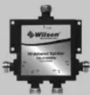
4-way
Installing the Signal Booster
Select a location for the signal booster which is away from excessive heat, direct sunlight, moisture and is not subject to high temperatures. Do not place the signal booster in an air-tight enclosure. Recommended installation locations for in-building signal boosters are in a closet or on a shelf where power is available. Attic installations may expose the booster to high heat.
Note: Do not install in areas subject to temperatures in excess of 150 °F .
Note: Maintain at least 6 inches of clearance from surrounding objects. Be careful when plugging the connector in so as not to damage the center pins on the connectors.
Run the outside antenna cable to the signal booster and attach it to the connector labeled "Outside Antenna" on the signal booster. Run the inside antenna cable to the signal booster and attach it to the connector labeled "Inside Antenna" on the signal booster.
Note: In order to abide by FCC regulations, cable lengths and antennas shipped as a kit with each booster must be used and not cut and shortened. Contact our tech support for cable kits to be used in situations requiring long cable runs.
Note: It is very important to power your signal booster using a surge protected AC power strip with at least a 1000 Joule rating. Failure to do this will void your warranty in the event of a power surge or lightning strike.
Finding the Strongest Signal
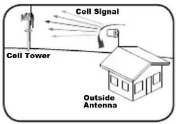
When installing your signal booster's outside antenna, aiming it towards the best signal source from your carrier is important. The best way of getting the strongest signal is to use the Wilson Signal Meter and accessory Directional Antenna (see outside antenna kit options on page 14), an alternate way is to have one person on the roof to rotate the outside antenna, which is connected to the signal booster. Turn the outside antenna about 45 degrees at a time, while the second person, inside the building, is watching the signal strength on a signal meter (preferred) or a phone in test mode. This allows you to read the signal strength from the cell tower. The phone should be in the test mode so the actual signal strength can be read, as bars are not the most accurate. Always make sure the person inside the building gives the signal strength time to register on the phone (at least 30 seconds for phone to update the signal reading).
text_image
Cell Signal Cell Tower Outside Antenna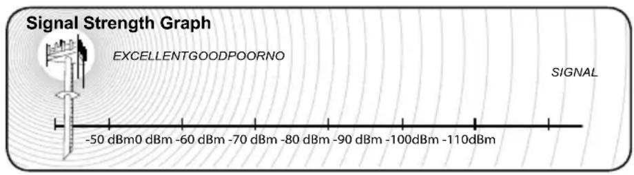
text_image
Signal Strength Graph EXCELLENTGOODPOORNO -50 dBm0 dBm -60 dBm -70 dBm -80 dBm -90 dBm -100dBm -110dBm SIGNALSignal readings usually appear as a negative number (for example, -86). The closer the number to zero, the stronger the signal (see Signal Strength Graph above).
Post Install Setup
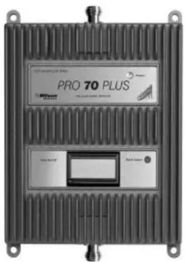
The Pro Series booster is designed with advanced internal programming which allows it to automatically adjust itself for a variety of conditions and still boost weak signals. After completing the amplifier installation, the LCD display and push button on the lower panel of the Pro Series booster is used to verify the final gain that the booster adjusted itself to produce after antennas have been placed. The display can also be used (if necessary) to re-adjust antennas so the booster can produce maximum gain and therefore, coverage. The LCD screen will show status for each band and inform the installer if any bands may have had their gain reduced by the booster's internal programming. In addition, an indicator light on the booster's upper panel will help diagnose the overall status of the booster by glowing in different colors. This will be covered in the following page.
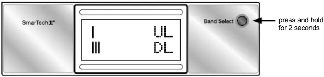
The Pro Plus booster has an integrated graphical meter to simplify the installation process. This is not to replace your signal meter - rather it complements the use. The bar graphs will assist in the aiming of your outside antenna - the biggest graph indicates that you are receiving the best overall signal.
To access this feature for the currently displayed frequency band, press and hold the "Band Select" button for 2 seconds. This will change the display to the UL/DL bar graph (uplink/downlink). A quick press of the button will move to the next band (briefly showing the band, before returning back to the bar graph); while holding the button will return to the regular display.
text_image
SmarTechⅡ* I UL III DL Band Select press and hold for 2 secondsUnderstanding the LCD Screen
- Four bands can be individually selected:
a The 700 MHz LTE Bands (B12/17 and B13)
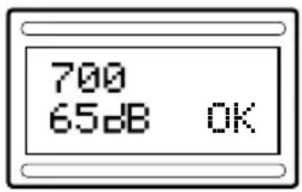
text_image
700 65dB OKb The 800 MHz Band – Cell Band
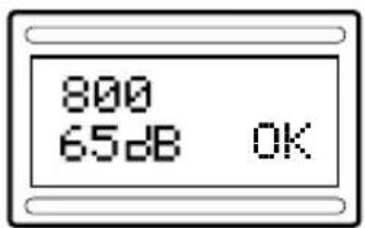
text_image
800 65dB OKC The 1900 MHz
- PCS Band
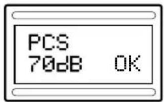
text_image
PCS 70dB OKd 1700/2100 MHz
- AWS Band
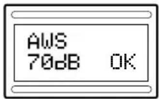
text_image
AWS 70dB OKThe single "BAND SELECT" button is used to scroll the display through the four cellular bands in order to verify that each band is functioning properly. An asterisk (located next to the band selected) will flash if one or more bands have been turned down/off by the boosters control circuitry due to strong nearby cell site signal overload ("OVL") and/or oscillation detection ("OSC") from antennas being too close. This is no cause for concern if the power light remains green and you are satisfied with your indoor coverage area.
Understanding the Upper Panel Indicator Light
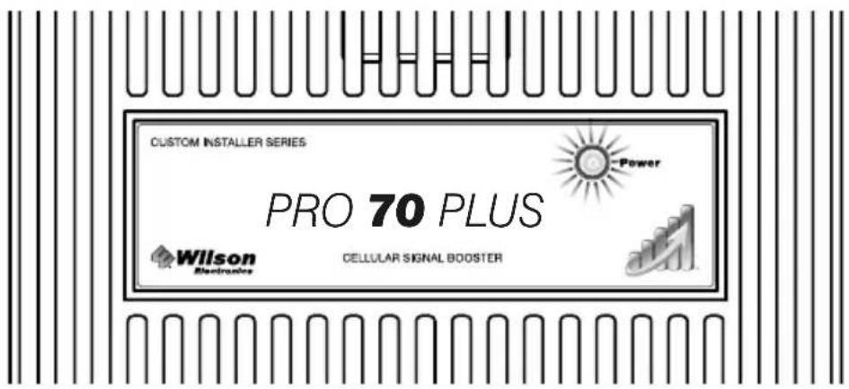
As the LCD display is being toggled through the four cellular bands, the upper indicator light (power) will glow green, orange, or red on each selected band, depending on how the booster is functioning on each band as explained below.
text_image
CUSTOM INSTALLER SERIES PRO 70 PLUS Wilton Electronics Power CELLULAR SIGNAL BOOSTERGreen indicates the unit is powered and working properly.
Red indicates the booster has shut down due to extreme oscillation (feedback).
Orange indicates the booster has shut down due to extreme signal overload. This is caused from being too close to a cell tower.
Fixing Red Light Issues
If the power light is red:
- Make sure all connections are tight.
- You need to increase the distance between the outside antenna and the inside antenna by moving them horizontally and/or vertically farther apart. After doing so, reset the booster by unplugging the power supply and then plugging it back in. If the light is green after separating the antennas, you have eliminated the problem.
- If your coverage area is still too small after separating the antennas contact the Wilson Electronics Customer Support Team for assistance: 866-839-9361.
Fixing Orange Light Issues
If the power light is orange:
- It will be necessary to turn the outside antenna away from the nearby cellular signal in small increments until the light turns green. If the Signal Booster will not respond, relocation of the outside antenna may be required.
- If the light remains orange, contact the Wilson Electronics Customer Support Team for assistance at 866-839-9361.
About Wilson Electronics
Wilson Electronics, LLC has been a leader in the wireless communications industry for over 40 years. The company designs and manufactures Signal Boosters, antennas and related components that significantly improve cellular telephone signal reception and transmission in a wide variety of applications, mobile (marine, RV, vehicles) and in-building (home, office, machine to machine).
With extensive experience in antenna and Signal Booster research and design, the company's engineering team uses a state-of-the-art testing laboratory, including an anechoic chamber and network analyzers, to fine-tune antenna designs and performance. For its Signal Boosters, Wilson Electronics uses a double electrically shielded RF enclosure and cell tower simulators for compliance testing.
Wilson Electronics Signal Boosters feature patented SmarTech ^® that enables them to automatically adjust their power based on cell tower requirements. By detecting and preventing oscillation (feedback), signal overload and interference with other users, these SmarTech ^® Signal Boosters improve network cell phone areas without compromising carrier systems.
All products are engineered and assembled in the company's 100,000 square-foot headquarters in St. George, Utah. Wilson Electronics has product dealers in all 50 states as well as in countries around the world.
Warnings and Recommendations

WARNING:
To uphold compliance with network protection standards, all active cellular devices must maintain at least 6 feet of separation distance from Panel and Dome antennas.

WARNING:
Connecting the Signal Booster directly to the cell phone with use of an adapter will damage the cell phone.

WARNING:
Use only the power supply provided in this package. Use of a non-Wilson Electronics product may damage your equipment.

WARNING:
The Signal Booster unit is designed for use in an indoor, temperature-controlled environment (less than 150 degrees Fahrenheit). It is not intended for use in attics or similar locations subject to temperatures in excess of that range.

WARNING:
Warning: The Outside Antenna must be installed no higher than 10 meters (32'9") above ground.

WARNING:
Take care to ensure that neither you nor the pole comes near any power lines during installation.

RF SAFETY WARNING: Any antenna used with this device must be located at least inches from all persons.
This is a CONSUMER device.
BEFORE USE, you MUST REGISTER THIS DEVICE with your wireless provider and have your provider's consent. Most wireless providers consent to the use of signal boosters. Some providers may not consent to the use of this device on their network. If you are unsure, contact your provider.
In Canada, BEFORE USE you must meet all requirements set out in ISED CPC-2-1-05. You MUST operate this device with approved antennas and cables as specified by the manufacturer. Antennas MUST be installed at least 20 cm (8 inches) from (i.e., MUST NOT be installed within 20 cm of) any person.
You MUST cease operating this device immediately if requested by the FCC (or ISED in Canada) or licensed wireless service provider.
WARNING. E911 location information may not be provided or may be inaccurate for calls served by using this device.
This device may be operated ONLY in a fixed location (i.e..may operate in a fixed location only) for in-building use.
Note: For a complete list of antennas and cables approved for use with these boosters see pages 14 & 15.
This device complies with Part 15 of FCC rules. Operation is subject to two conditions: (1) This device may not cause harmful interference, and (2) this device must accept any interference received, including interference that may cause undesired operation. Changes or modifications not expressly approved by Wilson Electronics could void the authority to operate this equipment.
Inside Antenna Expansion Kit
(contact Wilson Technical Support for assistance)
Kit 309900-50N
2 - Wall Panel antennas
1 - 50 ohm 3-Way Splitter
Kit 309905-50N
3 - Wall Panel Antennas
3 - 2-Way 50 Ohm Splitters
Kit 309902-75F
2 - Wall Panel Antennas
1 - 3-Way 75Ohm Splitter
Kit 309903-75F
3 - Wall Panel Antennas
3 - 2-Way 75Ohm Splitters
Kit 309904-75F
1 - Wall Panel Antenna
1 - 2-Way 75 Ohm Splitter
Inside Antenna Kits
(contact Wilson Technical Support for assistance)
Kit 311155-0630
75 Ohm Wall Mount Panel Antenna
30' RG6
Kit 311135-5820
50 Ohm Wall mount Panel Antenna
20' RG58 Cable
Kit 311135-40060
50 Ohm Wall Mount Panel Antenna
60' LMR400 Cable
Kit 311155-1150
75 Ohm Wall mount Panel Antenna
50' RG11 Cable
Kit 304412-40010
50 Ohm 4G Dome Antenna
10' Wilson400 cable
Kit 304412-5810
50 Ohm 4G Dome Antenna
10' RG58 cable
Kit 304419-1110
75 Ohm 4G Dome Antenna
10' RG 11 cable
Kit 304419-17410
75 Ohm 4G Dome Antenna
10' RG174 cable
*May need separate adapter
Kit 304419-0610
75 Ohm 4G Dome Antenna
10' RG6 cable
Kit 301213
Desktop Antenna w/ 5' RG174
50 Ohm Outside Antenna Kits
(contact Wilson Technical Support for assistance)
Kit 314453-5825
50 Ohm Pole Mount Panel Antenna
25' RG58 Cable
Kit 314411-5825
50 Ohm Wide Band Directional
25' RG58 Cable
Kit 301111-5850
Yagi Directional Antenna
50' RG58 Cable
Kit 311203-5820
Omni-Directional antenna
20' RG58 Cable
Kit 311203-40020
Omni-Directional antenna
20' LMR400 Cable
Kit 301111-400170
Yagi Directional w/ N-Female
170' LMR400
Kit 314411-40075
50 Ohm Wide Band Directional Antenna
75' LMR400 Cable
Kit 314453-40075
50 Ohm Pole Mount Panel Antenna
75' LMR400 Cable
Kit 304422-40020
50 Ohm 4G Omni Antenna
20' Wilson400 cable
Kit 304422-5810
50 Ohm 4G Omni Antenna
10' RG58 cable
Kit 304422-1120
50 Ohm 4G Omni Antenna
20' RG11 cable
*May need separate adapter
75 Ohm Outside Antenna Kits
(contact Wilson Technical Support for assistance)
Kit 301111-0675
Yagi Directional Antenna
75' RG6 Cable
N-Male to F-Female adapter
Kit 311201-0620
Omni Directional w/ F-Female
20' RG6 Cable
Kit 311141-0620
75 Ohm Grey Brick Antenna
20' RG6 Cable
Kit 301111-11140
Yagi Directional Antenna
140' RG11 Cable
N-Male to F-Female adapter
Kit 311201-1120
Omni Directional w/ F-Female
20' RG11 Cable
Kit 314473-1175
75 Ohm Pole Mount Panel Antenna
75' RG11 Cable
Kit 314475-1175
75 Ohm Wide Band Directional
75' RG11 Cable
Kit 311141-1120
75 Ohm Grey Brick Antenna
20' RG11 Cable
Kit 304421-1120
75 Ohm 4G Omni Antenna
20' RG 11 cable
Kit 304421-17410
75 Ohm 4G Omni Antenna
10' RG174 cable
Kit 304421-0610
75 Ohm 4G Omni Antenna
10' RG6 cable
Kit 304421-5810
75 Ohm 4G Omni Antenna
10' RG58 cable
*May need separate adapter
Mini-Mag Outside Antenna
(contact Wilson Technical Support for assistance)
301126 w/12.5 RG174 cable-SMA
30-Day Money-Back Guarantee
All Wilson Electronics products are protected by Wilson Electronics 30-day money-back guarantee. If for any reason the performance of any product is not acceptable, simply return the product directly to the reseller with a dated proof of purchase.
3-Year Warranty
Wilson Electronics Signal Boosters are warranted for three (3) years against defects in workmanship and/or materials. Warranty cases may be resolved by returning the product directly to the reseller with a dated proof of purchase.
Signal Boosters may also be returned directly to the manufacturer at the consumer's expense, with a dated proof of purchase and a Returned Material Authorization (RMA) number supplied by Wilson Electronics. Wilson Electronics shall, at its option, either repair or replace the product. Wilson Electronics will pay for delivery of the repaired or replaced product back to the original consumer if located within the continental U.S.
This warranty does not apply to any Signal Booster determined by Wilson Electronics to have been subjected to misuse, abuse, neglect, or mishandling that alters or damages physical or electronic properties.
Replacement products may include refurbished Wilson Electronics products that have been recertified to conform with product specifications.
Failure to use a surge protected AC Power Strip with at least a 1000 Joule rating will void your warranty.
RMA numbers may be obtained by contacting Customer Support at 866-294-1660.
Disclaimer : The information provided by Wilson Electronics, LLC is believed to be complete and accurate. However, no responsibility is assumed by Wilson Electronics, LLC for any business or personal losses arising from its use, or for any infringements of patents or other rights of third parties that may result from its use.
Copyright © 2017 Wilson Electronics, LLC All rights reserved.
U.S. Patent Nos. - 7,221,967; 7,729,669; 7,486,929; 7,409,186; 7,783,318; 8,583,034; 8,583,033; 8,874,030 B2;
8,874,029 B2; 8,755,399; 8,849,187 B2; 8,639,180; D703, 181
Notes
Notes
Signal Booster Specifications
| Pro 70 PlusTM 50 Ohm | |||||
| Product Number U651034 | |||||
| Model Number 463027 | |||||
| FCC ID | PWO460027 | ||||
| IC ID | 4726A-460027 | ||||
| Connectors N-F | emale | ||||
| Antenna Impedance 50 Ohms | |||||
| Frequency 698-716 MHz, 746-787 MHz, 824-894 MHz, 1850-1995 MHz, 1710-1755/2110-2155 MHz | |||||
| Passband Gain (nominal) | 700MHz Band12/1756.0 | 700MHz Band1355.2 | 800MHz58.9 | 1700/2100MHz60.7 | 1900MHz60.7 |
| 20 dB Bandwidth (MHz) | 700MHz Band12/17 | 700MHz Band13 | 800MHz | 1700/2100MHz | 1900MHz |
| Typical Maximum | 29.934.4 | 28.634.4 | 38.740.3 | 82.685.0 | 81.885.9 |
| Power output for single cell phone (Uplink) dBm | 700MHz Band12/17 | 700MHz Band13 | 800MHz | 1700MHz | 1900MHz |
| 20.4 20.82 25.16 23.0 | 21.42 | ||||
| Power output for single cell phone (Downlink) dBm | 700MHz Band12/17 | 700MHz Band13 | 800MHz | 2100MHz | 1900MHz |
| 11.57 | 10.41 | 9.4 | 11.3 | 9.47 | |
| Power output for multiple received channels (Uplink) dBm No. Tones | 700MHz Band12/17 | 700MHz Band13 | 800MHz | 1700MHz | 1900MHz |
| 2 | 18.0 | 17.6 | 24.9 | 20.0 | 18.6 |
| 3 | 14.5 | 14.0 | 21.4 | 16.4 | 15.1 |
| 4 | 12.0 | 11.5 | 18.9 | 13.9 | 12.6 |
| 5 | 10.0 | 9.6 | 16.9 | 12.0 | 10.7 |
| 6 | 8.4 | 8.0 | 15.3 | 10.4 | 9.1 |
| Power output for multiple received channels (Downlinklink) dBm No. Tones | 700MHz Band12/17 | 700MHz Band13 | 800MHz | 2100MHz | 1900MHz |
| 2 | 9.50 | 7.60 | 10.00 | 11.70 | 9.10 |
| 3 | 6.00 | 4.10 | 6.50 | 8.20 | 5.60 |
| 4 | 3.50 | 1.60 | 4.00 | 5.70 | 3.10 |
| 5 | 1.60 | -0.40 | 2.00 | 3.80 | 1.10 |
| 6 | 0.00 | -1.90 | 0.40 | 2.20 | -0.40 |
| Noise Figure 5 dB nominal | |||||
| Isolation | >90 dB | ||||
| Power Requirements | 110-240 V AC, 50-60 Hz, 20 W | ||||
Each Signal Booster is individually tested and factory set to ensure FCC compliance. The Signal Booster cannot be adjusted without factory reprogramming or disabling the hardware. The Signal Booster will amplify, but not alter incoming and outgoing signals in order to increase coverage of authorized frequency bands only. If the Signal Booster is not in use for five minutes, it will reduce gain until a signal is detected. If a detected signal is too high in a frequency band, or if the Signal Booster detects an oscillation, the Signal Booster will automatically turn the power off on that band. For a detected oscillation the Signal Booster will automatically resume normal operation after a minimum of 1 minute. After 5 (five) such automatic restarts, any problematic bands are permanently shut off until the Signal Booster has been manually restarted by momentarily removing power from the Signal Booster. Noise power, gain, and linearity are maintained by the Signal Booster's microprocessor.

WILSON
ELECTRONICS
3301 East Deseret Drive, St. George, UT
www.wilsonelectronics.com | tech@wilsonelectronics.com
Copyright © 2016 Wilson Electronics. All rights reserved.
Wilson Electronics products covered by U.S. patent(s) and pending application(s)
For patents go to: weboost.com/us/patents


PRO SERIES
GUIDE D'INSTALLATION
text_image
PRO 70 PLUS WProPower PRO 70 PLUS Control knobs Control knobsnatural_image
Abstract grayscale image with a faint circular shape and curved line, no text or symbols present.text_image
AWS 70dB OK8,583,033; 8,874,030 B2; 8,874,029 B2; 8,755,399; 8,849,187 B2; 8,639,180; D703, 181