
48228590 - Mobile storage furniture MILWAUKEE - Free user manual and instructions
Find the device manual for free 48228590 MILWAUKEE in PDF.
| Product Type | Mobile Storage Cabinet |
| Brand | Milwaukee |
| Model | 48-22-8590 (48228590) |
| Total Capacity | 317.5 kg (700 lbs) |
| Top Tray Capacity | 136.0 kg (300 lbs) |
| Top Drawer Capacity | 45.4 kg (100 lbs) |
| Bottom Shelf Capacity | 90.7 kg (200 lbs) |
| Swivel Shelf Capacity | 22.7 kg (50 lbs) |
| Storage Tray Capacity | 22.7 kg (50 lbs) |
| Power Supply | 120 V~, 60 Hz, 15 A |
| USB Port (Voltage / Current / Power) | 5 V / 2.1 A / 10.5 W |
| Operating Temperature | -15 °C to 40 °C (5 °F to 104 °F) |
| Wheels | 2 swivel casters with brake + 2 fixed casters |
| Foldable Work Tray | Yes, with cutting notches |
| Central Lock | Yes (key, locks drawers and lid) |
| Material | Steel with powder coating |
| Warranty | 3 years (parts and labor) |
| Maintenance | Clean with mild detergent; lubricate slides every 6 months, casters annually |
| Included Accessories | Tool holders, cord storage brackets, storage bar |
Frequently Asked Questions - 48228590 MILWAUKEE
User questions about 48228590 MILWAUKEE
0 question about this device. Answer the ones you know or ask your own.
Ask a new question about this device
Download the instructions for your Mobile storage furniture in PDF format for free! Find your manual 48228590 - MILWAUKEE and take your electronic device back in hand. On this page are published all the documents necessary for the use of your device. 48228590 by MILWAUKEE.
USER MANUAL 48228590 MILWAUKEE
Cat. No. / No de cat.
48-22-8590
40" STEEL WORK CART
CHARIOT DE TRAVAIL EN ACIER DE 1,01 m (40")
CARRO DE TRABAJO DE ACERO DE 1,01 m (40")

WARNING To reduce the risk of injury, user must read and understand operator's manual.
IMPORTANT SAFETY INSTRUCTIONS
WARNING
Read all safety warnings and all instructions. Failure to follow the warnings and instructions may result in serious injury. Save all warnings and instructions for future reference.
- Use the station and accessories in accordance with these instructions and in the manner intended, taking into account the working conditions. Use of the station for operations different from those intended could result in a hazardous situation.
- Keep work area clean and well lit. Cluttered or dark areas invite accidents.
- Fully assemble the station according to the assembly instructions. Do not leave off any pieces.
- Do not modify the station in any way. Use only specifically recommended accessories. Drilling holes or modifying the station will lower the load capacity, which can cause the station to collapse, resulting in injury.
- Lock wheels when station is not being moved. Unlocked wheels can allow the station to move unexpectedly.
- Keep the station on a level surface. Do not load, unload, or park station on an incline. The station may become unbalanced and tip, resulting in injury.
- Always balance the station load to avoid tipping Unbalanced stations are more likely to tip when being moved or when using the station work surfaces. Evenly distribute the weight front to back and side to side. To help prevent the station from tipping, load the product starting with the bottom drawers.
- Do not exceed the maximum product weight, including contents. Do not exceed the maximum weight for each drawer. Overloaded stations can tip, collapse, or damage drawer slides.
- Do not open more than one drawer at a time. Station may tip, causing injury.
- Keep children and bystanders away while loading, unloading, and moving the station. Distractions can cause you to lose control.
- Only lift the station according to the instructions in this manual. Never lift by the side handle. Other methods may be dangerous, resulting in injury.
- Only transport the station when empty. Properly secure when transporting.
- Do not mount the station on a truck bed or any other moving object.
- Lock all drawers before rolling the station. The drawers could come open and make the station unstable and tip.
- Only roll the station short distances by using the handle provided.
- Secure all items before rolling the station. Loose items could shift, causing the station to become unstable.
- Do not use drawers as steps. Do not stand on the station. Station may tip, causing injury.
- Do not step on side shelf. Shelf may collapse or break. Station may tip, causing injury.
- Do not use station in explosive atmospheres, such as in the presence of flammable liquids, gases or dust. This equipment has internal arcing or sparking parts. Station should not be located in a recessed area or below floor level.
- Station plugs must match the outlet. Never modify the plug in any way. Do not use any adapter plugs with earth (grounded) chest/cabinet power
strips. Unmodified plugs and matching outlets will reduce risk of electric shock.
- Avoid body contact with earthed or grounded surfaces such as pipes, radiators, ranges and refrigerators. There is an increased risk of electric shock if your body is earthed or grounded.
- Maintain station. Check for misalignment or binding wheels, breakage or bending of drawer slides or other parts and any other condition that may affect the station's operation. Do not use damaged station.
- Maintain labels and nameplates. These carry important information. If unreadable or missing, contact a MILWAUKEE service facility for a free replacement.
- Have your station serviced by a qualified repair person using only identical replacement parts.
This will ensure that the safety of the station is maintained.
Federal Communications Commission
WARNING: Changes or modifications to this unit not expressly approved by the party responsible for compliance could void the user's authority to operate the equipment.
This device complies with Part 15 of the FCC Rules. Operation is subject to the following two conditions: (1) this device may not cause harmful interference, and (2) this device must accept any interference received, including interference that may cause undesired operation.
NOTE: This equipment has been tested and found to comply with the limits for a Class B digital device, pursuant to Part 15 of the FCC Rules. These limits are designed to provide reasonable protection against harmful interference in a residential installation. This equipment generates, uses and can radiate radio frequency energy and, if not installed and used in accordance with the instructions, may cause harmful interference to radio communications. However, there is no guarantee that interference will not occur in a particular installation. If this equipment does cause harmful interference to radio or television reception, which can be determined by turning the equipment off and on, the user is encouraged to try to correct the interference by one or more of the following measures:
- Reorient or relocate the receiving antenna.
- Increase the separation between the equipment and receiver.
- Connect the equipment into an outlet on a circuit different from that to which the receiver is connected.
- Consult the dealer or an experienced radio/TV technician for help.
SPECIFICATIONS
Cat. No. 48-22-8590
Top Tray Capacity....300 lbs. (136.0 kg)
Top Drawer Capacity ....100 lbs. (45.4 kg)
Bottom Tray Capacity ....200 lbs. (90.7 kg)
Flip Up Shelf Capacity....50 lbs. (22.7 kg)
Storage Tray Capacity....50 lbs. (22.7 kg)
Total Capacity....700 lbs. (317.5 kg)
AC Input Volts....120
Hertz....60
Amps 15
USB Output Volts....5
USB Watts 10.5
USB Amps 2.1
Recommended Ambient Operating
Temperature .....5°F to 104°F (-15°C to 40°C)
SYMBOLOGY
GROUNDING
Warning

d Operator's Manual

trical Shock Hazard

Do not open more than one drawer at a Station may tip, causing injury.
Lock wheels when station is not being moved. Unlocked wheels can allow the station to move unexpectedly.

Do not use drawers as steps. Station tip, causing injury.

Lock all drawers before moving the station.

Unplug power strip before moving the station.
FUNCTIONAL DESCRIPTION
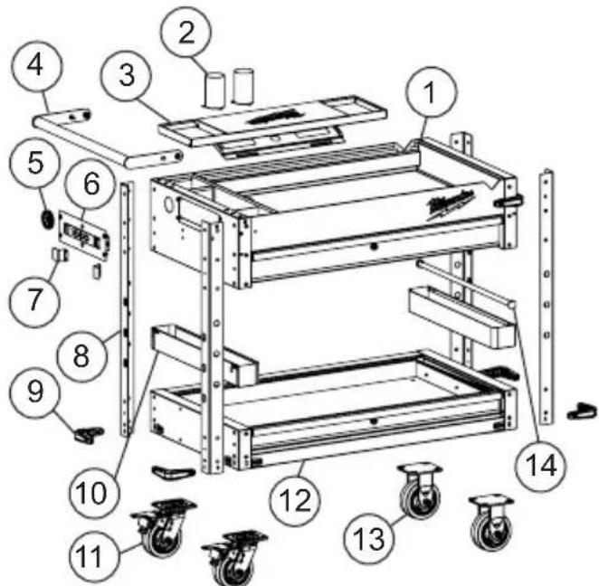
- Top tray frame
- Tooling cup
- Fold-out work tray
- Side handle
- Grommet
- Power strip
-
Cord storage brackets
-
Post
- Bumper
- Storage tray
- Swivel caster with brake
- Bottom tray frame
- Rigid caster
- Storage bar
⚠ WARNING Improperly connecting the grounding wire can result in the risk of electric shock. Check with a qualified electrician if you are in doubt as to whether the outlet is properly grounded. Do not modify the plug provided with the station. Never remove the grounding prong from the plug. Do not use the station if the cord or plug is damaged. If damaged, have it repaired before use. If the plug will not fit the outlet, have a proper outlet installed by a qualified electrician.
Stations with Three Prong Plugs
Stations marked "Grounding Required" have a power strip with a three wire cord and three prong grounding plug. The plug must be connected to a properly grounded outlet (See Figure A). If the power strip should electrically malfunction or break down, grounding provides a low resistance path to carry electricity away from the user, reducing the risk of electric shock.
The grounding prong in the plug is connected through the green wire inside the cord to the grounding system in the power strip. The green wire in the cord must be the only wire connected to the power strip's grounding system and must never be attached to an electrically "live" terminal.
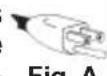
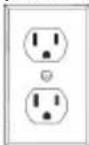
Your power strip must be plugged into an appropriate outlet, properly installed and grounded in accordance with all codes and ordinances. The plug and outlet should look like those in Figure A.
ASSEMBLY
CAUTION Be sure to follow the assembly instructions for the appropriate station. Do not use power tools to assemble station. Tighten bolts with hand wrenches.
Phillips
screwdriver
Tools Required
Safety goggles
10 mm Wrench
13 mm Wrench
Hardware Included
NOTE: Items not shown to actual size. Hardware lengths are approximate.
| Hardware | Item | Description | Quantity |
| AA | 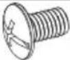 | Screw M6 x 16L 40 | |
| BB | 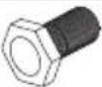 | Screw M8 x 18L | 16 |
| CC | 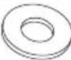 | WasherM19 x 8.5 x 2 | 16 |
| DD |  | Screw M4 x 12L | 8 |
| EE | 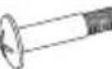 | Screw M6 x 25L | 2 |
| FF | 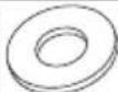 | Nylon WasherM18 x 8.5 x 1.5 | 4 |
| GG |  | WasherM12 x 6 x 0.8 | 2 |
| HH Nut | 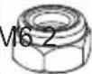 | ||
| II Screw | 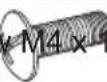 | 6L 12 | |
| JJ | 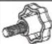 | Bolt (with Plastic)M6 | 1 |
| KK |  | Cord StorageBracket | 2 |
| LL Rubt |  | per 6 | |
| MM | 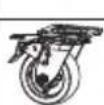 | Swivel Casterwith Brake | 2 |
| NN Rigid |  | 2 | |
| OO | 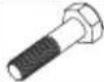 | Hexagonal HeadBolt M6 x 25L | 2 |
Installing the Frame
- Ensure all station drawers are securely locked into place using the key lock on the station.
- Lay the bottom tray frame down. Use the packaging material to protect the finish.
- Attach the posts one at a time to the bottom frame using four screws (AA) per post.
NOTE: Position the posts so that the bottoms show four holes, and the tops six.
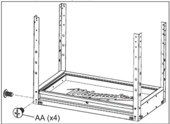
- Lay the top tray frame upside down. Use the packaging material to protect the finish.
- Attach the bottom tray frame with posts to the top frame using six screws (AA) per post.

natural_image
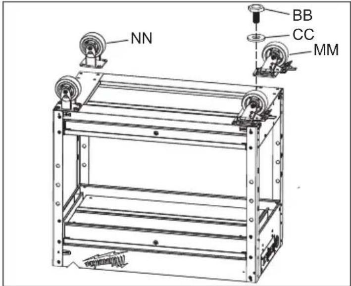
Technical line drawing of a multi-tiered mechanical housing with screw base and mounting holes (no text or symbols)Installing the Casters
⚠️ CAUTION Do not overtighten the screws.
- Mount the two swivel casters with brake to the station using four screws (BB) and washers (CC) per caster. The swivel casters with brake should be installed on the end of the station with the power strip and side handle.
- Mount the two rigid casters to the opposite end of the station using four screws (BB) and washers (CC) per caster.
- Tighten all bolts securely with a wrench.
- Return the station to its upright position.
Installing the Side Handle
- Attach the side handle to the station using one screw (EE) secured by two nylon washers (FF), one washer (GG) and one nut (HH) per side.
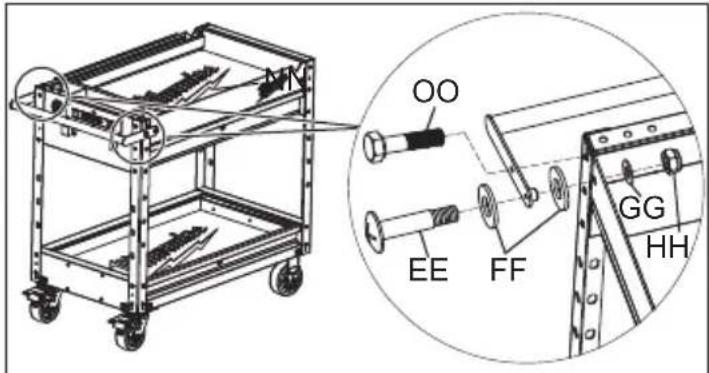
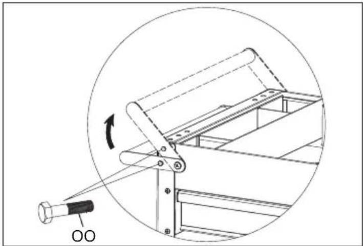
- To adjust the side handle height, install one bolt (OO) per side in either of the hole options shown below.
natural_image
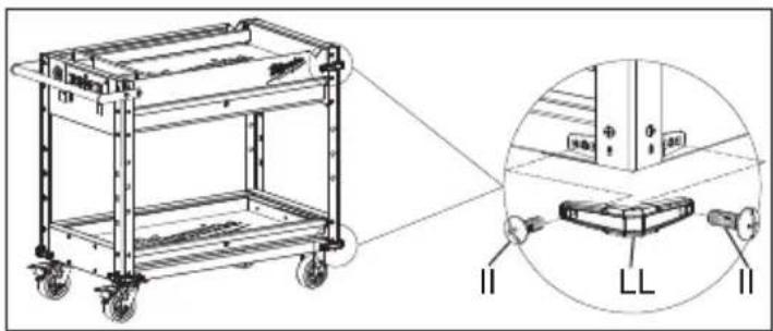
Technical diagram of a mechanical assembly with a rotating component and a pin (no text or symbols)Installing the Bumpers
Attach each bumper (LL) to the posts using two screws (II) per bumper.
NOTE: Bumpers cannot be installed where the side handle is located.
Attaching the Storage Trays
Attach each storage tray by hooking them onto the slots of the posts. The trays can be installed on either the inside or outside of the posts.
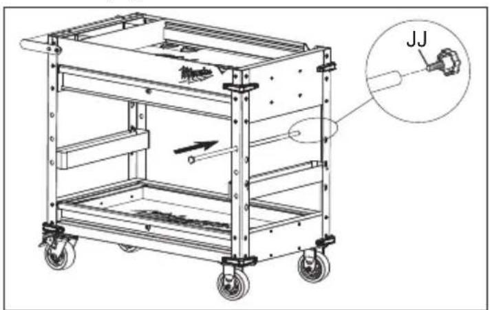
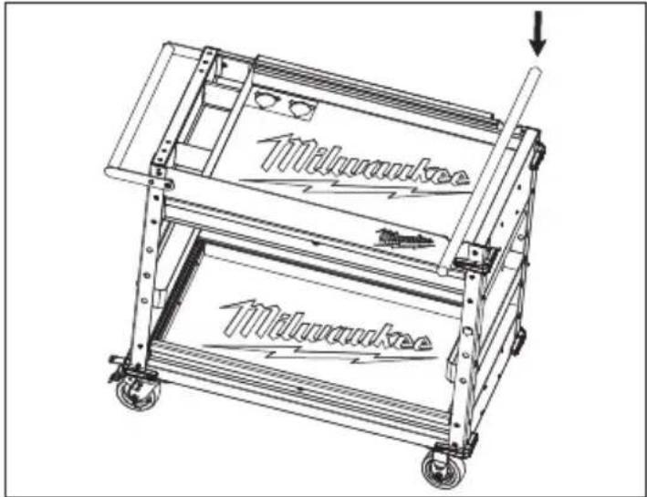
Installing the Storage Bar
- Remove the bolt (JJ) from the storage bar.
- Place the storage bar through any of the round slots in the desired post, as shown. Then reinstall the bolt (JJ) at the end of the rod.
natural_image
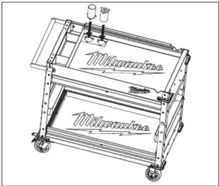
Technical line drawing of a multi-level industrial cart with wheels and a close-up inset showing a mechanical component labeled 'JJ' (no text or symbols on the cart itself)Installing the Tooling Cups
Attach each tooling cup by placing them in the top tray frame slots, and twisting to lock.
natural_image
Line drawing of a two-tiered moving cart with directional arrows and 'Milwaukee' branding on the side (no text or symbols beyond labels)Installing the Cord Storage Brackets
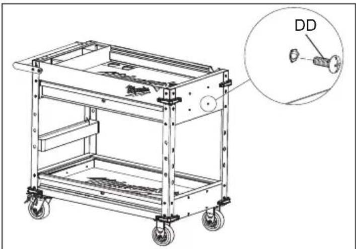
Attach the cord storage brackets (KK) to the station using two screws (DD) per bracket.
USB Power Outlet
The USB ports on the power outlet can be used to charge any device that uses less than 2.1A of DC electrical current.
NOTE: Any device that uses more than 2.1 A of DC electrical current will trip a self-resetting overload and disable the output.
OPERATION
⚠ WARNING To avoid injury or property damage, do not exceed maximum drawer capacity. Use care when moving the station on incline or rough surface. Station may tip if weight is not evenly distributed front to back and side to side. Place more than half the total load weight on the bottom drawers when possible.
Using the Lower Tray
The lower tray can be loaded to 200 lbs. To avoid tipping, the slides have limited travel. Distribute weight evenly from front to back and side to side.
Locking and Unlocking the Station
NOTE: The drawers must be fully closed before locking/unlocking the unit. Locks are located on both the top and bottom tray frames.
Insert the key. Turn it fully left to lock, or fully right to unlock. Always remove the key after locking and unlocking.
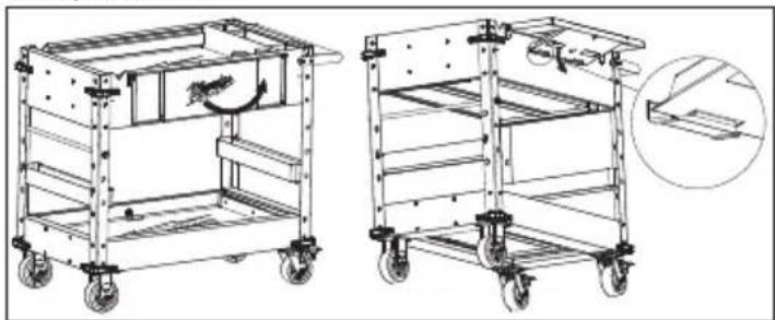
Using the Fold-Out Work Tray
To use the fold-out work tray, pull it out and secure to the station by latching the bottom half to the tray tabs, as shown.
natural_image
Technical line drawings of two multi-wheeled carts with wheels and a handle, shown from different angles (no text or symbols present)Using the Cutting Notches
To use the cutting notches, place the material to be cut over the notches. Ensure the station casters and drawers are locked, hold down the material and cut.
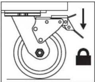
Using the Caster Brakes
To lock the swivel casters, step down on the levers marked ON. Be sure to lock all casters to prevent station from rolling or swiveling. To unlock casters, push down on the levers marked OFF.
Moving the Station on an Incline or Rough Surface
Take care that the station does not tip or become unbalanced when moving it on an incline or rough surface. Do not exceed an incline of 10 degrees. Lock the station and secure all items before moving.
Rolling the Station
The station is only intended for rolling short distances. Only roll the station using the handle. Do not push or pull station by the frame or product may tip. Do not modify the station in any way. Drilling holes or modifying the station will lower the load capacity, which can cause the station to collapse, resulting in injury. Lock the station and secure all items before rolling.
Lifting the Station
The station is not intended to be lifted. However, if you need to lift, empty the station and then place straps or forks inside and next to casters. Do not lift loaded stations. Never lift by the side handle. Be sure all bystanders are moved away before lifting station.
Mounting Chargers
The station comes equipped with twelve pre-installed charger mounting bosses. Four are located on the right side of the top tray, four on the left side of the bottom tray and another four on its right. The charger mounts are suitable for holding MILWAUKEE M18 ™ & M12 ™ Multi Voltage chargers as well as M18 ™ chargers.
To mount a charger, install a screw (DD) into each boss, then slide the charger's key-hole slots over the screws. Slide the charger toward the floor to lock it onto the screws.
NOTE: Four (DD) screws are included for the charger mounts.
natural_image
Technical line drawing of a multi-level industrial cart with wheels and a magnified inset showing a labeled component (no text or symbols present)MAINTENANCE
AWARNING To reduce the risk of injury, contact MILWAUKEE Corporate After Sales
Service Technical Support for ALL repairs and replacement parts.
Maintaining the Station
Keep your station in good repair by adopting a regular maintenance program. Before use, examine the general condition of your station. Check for loose screws, misalignment, binding of wheels, broken parts and any other condition that may affect its safe operation. Do not use a damaged station.
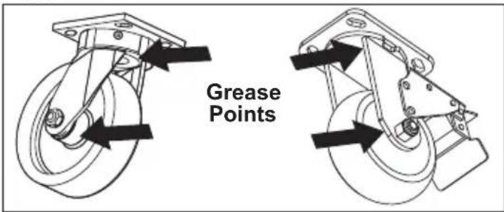
Maintaining the Casters
Grease the casters annually using high quality bearing grease.
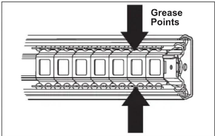
Maintaining the Drawers
- Periodically clean the drawer with a mild detergent and water.
- Remove grease and oil in drawer with a standard, nonflammable cleaning fluid.
- The use of drawer liners is recommended to protect the finish inside the drawers and ma the drawers easier to clean. Drawer liners can be cleaned with soap and water.
- Lubricate the slides semi-annually with general purpose grease or equivalent.
Cleaning
This steel product has been coated with industrial powder coating for a durable finish. To help protect the powder coated finish, do not allow harsh chemicals (oil, grease or other chemical) to remain on the powder coating surface. Use a glass cleaner to clean and maintain all surfaces of powder coating. Keep the station handles and wheels clean, dry and free of oil or grease. Use only mild soap and a damp cloth to clean your station since certain cleaning agents and solvents are harmful to plastics. Some of these include: gasoline, turpentine, lacquer thinner, chlorinated cleaning solvents, ammonia and household detergents containing ammonia. Never use flammable or combustible solvents around station.
Service
For service and repair information, including the ordering of service parts, call our Corporate After Sales Service Technical Support line at 1-800-SAWDUST, or visit our website at www.milwaukeeetool.com.
ACCESSORIES
WARNING Modifying the station to accept other accessories may be hazardous, resulting in injury or property damage. Use only specifically recommended accessories according to the manufacturer's instructions.
For a complete listing of accessories, go online to www.milwaukeeetool.com or contact a distributor.
SERVICE - UNITED STATES
1-800-SAWDUST (1.800.729.3878)
Monday-Friday, 7:00 AM - 6:30 PM CST
or visit www.milwaukeetool.com
Contact Corporate After Sales Service Technical Support with technical, service/repair, or warranty questions.
Email: metproductsupport@milwaukeeetool.com
Become a Heavy Duty Club Member at www.milwaukeetool.com to receive important notifications regarding your tool purchases.
SERVICE - CANADA
Milwaukee Tool (Canada) Ltd
1.800.268.4015
Monday-Friday, 7:00 AM - 4:30 PM CST
or visit www.milwaukeetool.ca
LIMITED WARRANTY USA & CANADA
Every MILWAUKEE steel storage chest and cabinet are warranted to the original purchaser from an authorized MILWAUKEE distributor only to be free from defects in material and workmanship. Subject to certain exceptions, MILWAUKEE will repair or replace any part on a chest or cabinet which, after examination, is determined by MILWAUKEE to be defective in material or workmanship for a period of three (3) years after the date of purchase. Return of the chest or cabinet to the place of purchase is required. A copy of the proof of purchase should be included with the return product. This warranty does not apply to damage that MILWAUKEE determines to be from repairs made or attempted by anyone other than MILWAUKEE authorized personnel, misuse, alterations, abuse, normal wear and tear, lack of maintenance, or accidents.
Warranty Registration is not necessary to obtain the applicable warranty on a MILWAUKEE steel storage chest or cabinet. The manufacturing date of the product will be used to determine the warranty period if no proof of purchase is provided at the time warranty service is requested. If you feel your product has a warranty defect, or if you need information on a service/replacement part, please contact MILWAUKEE at 1.800.SAWDUST for instructions.
ACCEPTANCE OF THE EXCLUSIVE REPAIR AND REPLACEMENT REMEDIES DESCRIBED HEREIN IS A CONDITION OF THE CONTRACT FOR THE PURCHASE OF EVERY MILWAUKEE PRODUCT. IF YOU DO NOT AGREE TO THIS CONDITION, YOU SHOULD NOT PURCHASE THE PRODUCT. IN NO EVENT SHALL MILWAUKEE BE LIABLE FOR ANY INCIDENTAL, SPECIAL, CONSEQUENTIAL OR PUNITIVE DAMAGES, OR FOR ANY COSTS, ATTORNEY FEES, EXPENSES, LOSSES OR DELAYS ALLEGED TO BE AS A CONSEQUENCE OF ANY DAMAGE TO, FAILURE OF, OR DEFECT IN ANY PRODUCT INCLUDING, BUT NOT LIMITED TO, ANY CLAIMS FOR LOSS OF PROFITS. SOME STATES DO NOT ALLOW THE EXCLUSION OR LIMITATION OF INCIDENTAL OR CONSEQUENTIAL DAMAGES, SO THE ABOVE LIMITATION OR EXCLUSION MAY NOT APPLY TO YOU. THIS WARRANTY IS EXCLUSIVE AND IN LIEU OF ALL OTHER EXPRESS WARRANTIES, WRITTEN OR ORAL. TO THE EXTENT PERMITTED BY LAW, MILWAUKEE DISCLAIMS ANY IMPLIED WARRANTIES, INCLUDING WITHOUT LIMITATION ANY IMPLIED WARRANTY OF MERCHANTABILITY OR FITNESS FOR A PARTICULAR USE OR PURPOSE; TO THE EXTENT SUCH DISCLAIMER IS NOT PERMITTED BY LAW, SUCH IMPLIED WARRANTIES ARE LIMITED TO THE DURATION OF THE APPLICABLE EXPRESS WARRANTY AS DESCRIBED ABOVE. SOME STATES DO NOT ALLOW LIMITATIONS ON HOW LONG AN IMPLIED WARRANTY LASTS, SO THE ABOVE LIMITATION MAY NOT APPLY TO YOU, THIS WARRANTY GIVES YOU SPECIFIC LEGAL RIGHTS, AND YOU MAY ALSO HAVE OTHER RIGHTS WHICH VARY FROM STATE TO STATE.
This warranty applies to product sold in the U.S.A. and Canada only. Please consult the 'Find a Service Center Search' in the Parts & Service section of MILWAUKEE's website www.milwaukeetool.com or call 1.800.SAWDUST (1.800.729.3878) to locate your nearest MILWAUKEE factory Service Center location.
INSTRUCTIONS IMPORTANTES CONCERNANT LA SÉCURITÉ
AVERTISSEMENT
Federal Communications Commission
natural_image
Technical line drawing of a modular electronic device with mounting screws and a labeled section (no text or symbols beyond labels)natural_image
Technical diagram of a mechanical assembly with a rotating component and a pin (no text or symbols)natural_image
Technical line drawing of a multi-level industrial cart with labeled components (II, LL, II) and an inset view showing internal components.natural_image
Technical line drawing of a multi-level industrial cart with wheels and a close-up inset showing a mechanical component labeled 'JJ' (no text or symbols on the cart itself)natural_image
Technical line drawings of two wheeled carts with wheels and a handle, shown from different angles (no text or symbols present)natural_image
Line drawing of a two-tiered mechanical cart with wheels and a handle, no text or symbols presentnatural_image
Technical line drawing of a multi-level industrial cart with wheels and a close-up inset showing a mechanical component labeled 'DD' (no text or symbols on the cart itself)Retrait des tiroirs
Milwaukee Tool (Canada) Ltd 1.800.268.4015
Monday-Friday, 7:00 AM - 4:30 PM CST
www.milwaukeetool.ca
GARANTIE LIMITÉE- AUX ÉTATS-UNIS ET AU CANADA
natural_image
Technical diagram of a mechanical assembly with a rotating component and a pin (no text or symbols)natural_image
Technical line drawing of a multi-wheeled cart with labeled components (II, LL, II) and an inset view showing internal components.natural_image
Technical line drawing of a multi-level industrial cart with wheels and a close-up inset showing a mechanical component labeled 'JJ' (no text or symbols on the cart itself)natural_image
Technical line drawings of two wheeled carts with wheels, one showing a handle mechanism and the other showing a detail view (no text or symbols)natural_image
Line drawing of a two-tiered mechanical cart with wheels and a downward arrow indicating motion (no text or symbols)natural_image
Mechanical diagram showing a wheel with a lock and directional arrow (no text or symbols)natural_image
Technical line drawing of a multi-wheeled cart with a magnified inset showing a small component labeled 'DD' (no text or symbols on the cart itself)Lunes a Viernes (9am a 6pm)
13135 West Lisbon Road
Brookfield, WI 53005 USA

- 40" STEEL WORK CART
- CHARIOT DE TRAVAIL EN ACIER DE 1,01 m (40")
- CARRO DE TRABAJO DE ACERO DE 1,01 m (40")
- IMPORTANT SAFETY INSTRUCTIONS
- WARNING
- Federal Communications Commission
- SPECIFICATIONS
- SYMBOLOGY
- GROUNDING
- Stations with Three Prong Plugs
- ASSEMBLY
- Hardware Included
- Installing the Frame
- ⚠️ CAUTION Do not overtighten the screws.
- Installing the Bumpers
- Attaching the Storage Trays
- Installing the Storage Bar
- Installing the Tooling Cups
- Installing the Cord Storage Brackets
- USB Power Outlet
- OPERATION
- Using the Lower Tray
- Locking and Unlocking the Station
- Using the Fold-Out Work Tray
- Using the Cutting Notches
- Using the Caster Brakes
- Moving the Station on an Incline or Rough Surface
- Rolling the Station
- Lifting the Station
- Mounting Chargers
- MAINTENANCE
- AWARNING To reduce the risk of injury, contact MILWAUKEE Corporate After Sales
- Maintaining the Station
- Maintaining the Casters
- Maintaining the Drawers
- Cleaning
- Service
- ACCESSORIES
- WARNING Modifying the station to accept other accessories may be hazardous, resulting in injury or property damage. Use only specifically recommended accessories according to the manufacturer's instructions.
- SERVICE - UNITED STATES
- 1-800-SAWDUST (1.800.729.3878)
- SERVICE - CANADA
- Milwaukee Tool (Canada) Ltd
- 1.800.268.4015
- LIMITED WARRANTY USA & CANADA
- INSTRUCTIONS IMPORTANTES CONCERNANT LA SÉCURITÉ
- AVERTISSEMENT
- Retrait des tiroirs
- Milwaukee Tool (Canada) Ltd 1.800.268.4015
- GARANTIE LIMITÉE- AUX ÉTATS-UNIS ET AU CANADA
Brand : MILWAUKEE
Model : 48228590
Category : Mobile storage furniture