DCK755P3T - Drill DEWALT - Free user manual and instructions
Find the device manual for free DCK755P3T DEWALT in PDF.
Download the instructions for your Drill in PDF format for free! Find your manual DCK755P3T - DEWALT and take your electronic device back in hand. On this page are published all the documents necessary for the use of your device. DCK755P3T by DEWALT.
USER MANUAL DCK755P3T DEWALT
WARNUNG: UM DIE GEFAHR SCHWERER
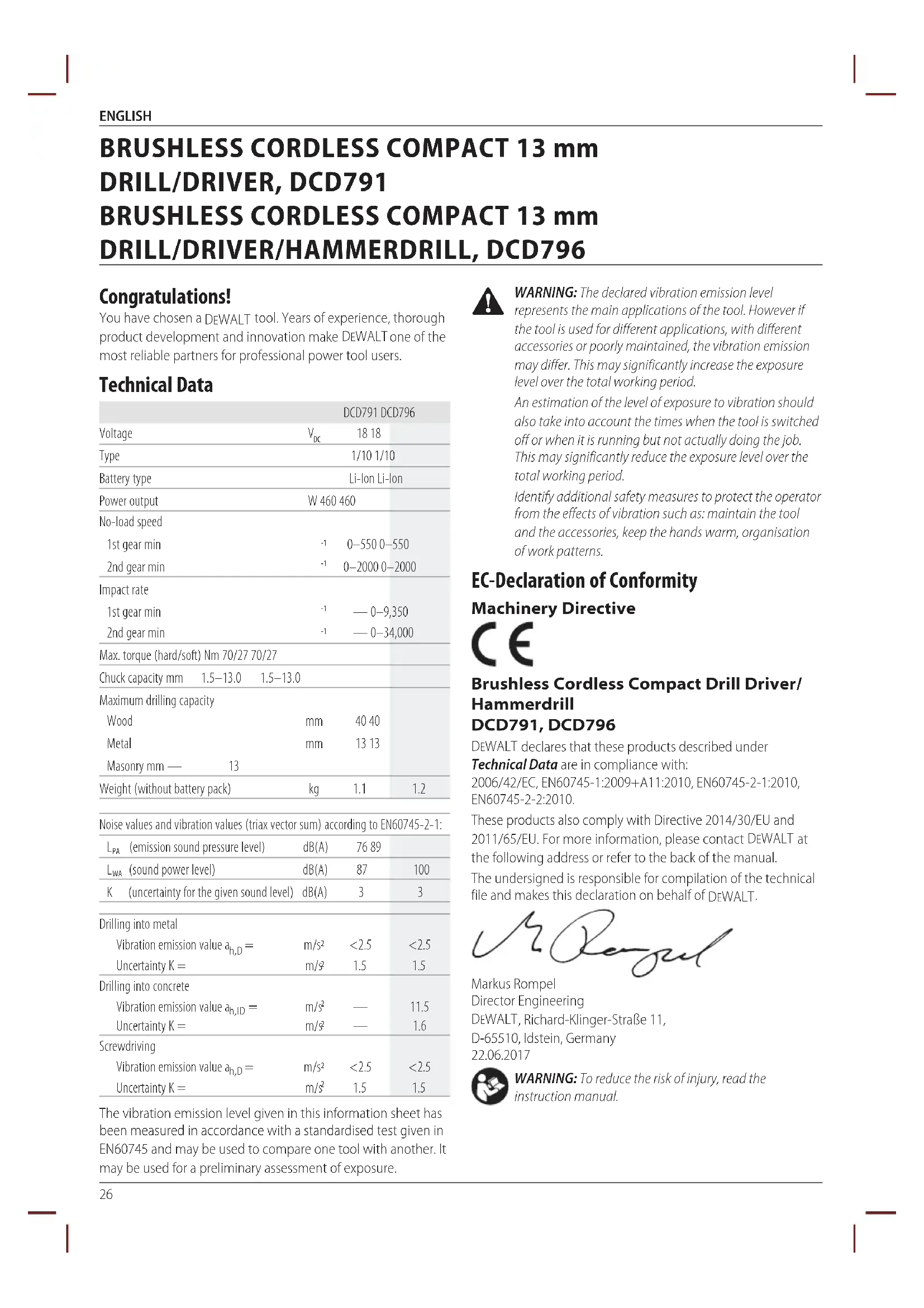
Congratulations! You have chosen a DEWALT tool. Years of experience, thorough product development and innovation make DEWALT one of the most reliable partners for professional power toolusers. Technical Data DCD791 DCD796 Voltage
0–550 0–550 2nd gear min
0–2000 0–2000 Impact rate 1st gear min
— 0–9,350 2nd gear min
— 0–34,000 Max. torque (hard/soft) Nm 70/27 70/27 Chuck capacity mm 1.5–13.0 1.5–13.0 Maximum drilling capacity Wood mm 40 40 Metal mm 13 13 Masonry mm — 13 Weight (without battery pack) kg
(emission sound pressure level) dB(A)
(sound power level) dB(A)
K (uncertainty for the given sound level) dB(A)
Drilling into metal Vibration emission value a h,D = m/s
Drilling into concrete Vibration emission value a h,ID = m/s
The vibration emission level given in this information sheet has been measured in accordance with a standardised test given in EN60745 and may be used to compare one tool with another. It may be used for a preliminary assessment ofexposure.
WARNING: The declared vibration emission level
represents the main applications of the tool. However if the tool is used for different applications, with different accessories or poorly maintained, the vibration emission may differ. This may significantly increase the exposure level over the total workingperiod. An estimation of the level of exposure to vibration should also take into account the times when the tool is switched off or when it is running but not actually doing the job. This may significantly reduce the exposure level over the total workingperiod. Identify additional safety measures to protect the operator from the effects of vibration such as: maintain the tool and the accessories, keep the hands warm, organisation of workpatterns. EC-Declaration of Conformity Machinery Directive Brushless Cordless Compact Drill Driver/ Hammerdrill DCD791, DCD796 DEWALT declares that these products described under Technical Data are in compliance with: 2006/42/EC, EN60745-1:2009+A11:2010, EN60745-2-1:2010, EN60745-2-2:2010. These products also comply with Directive 2014/30/EU and 2011/65/EU. For more information, please contact DEWALT
the following address or refer to the back of themanual. The undersigned is responsible for compilation of the technical file and makes this declaration on behalf of DEWALT
WARNING: To reduce the risk of injury, read the
instructionmanual.27 EnGLIsH Definitions: Safety Guidelines The definitions below describe the level of severity for each signal word. Please read the manual and pay attention to thesesymbols.
DANGER: Indicates an imminently hazardous
situation which, if not avoided, will result in death or seriousinjury.
WARNING: Indicates a potentially hazardous situation
which, if not avoided, could result in death or seriousinjury.
CAUTION: Indicates a potentially hazardous situation which, if not avoided, may result in minor or moderateinjury. NOTICE: Indicates a practice not related to personal injury which, if not avoided, may result in propertydamage.
Denotes risk of electricshock.
Denotes risk offire. General Power Tool Safety Warnings
WARNING: Read all safety warnings and all
instructions. Failure to follow the warnings and instructions may result in electric shock, fire and/or seriousinjury.
The term “power tool” in the warnings refers to your mains- operated (corded) power tool or battery-operated (cordless) powertool.
a ) Keep work area clean and well lit. Cluttered or dark areas inviteaccidents. b ) Do not operate power tools in explosive atmospheres, such as in the presence of flammable liquids, gases or dust. Power tools create sparks which may ignite the dust orfumes. c ) Keep children and bystanders away while operating a power tool. Distractions can cause you to losecontrol.
2) Electrical safety
a ) Power tool plugs must match the outlet. Never modify the plug in any way. Do not use any adapter plugs with earthed (grounded) power tools. Unmodified plugs and matching outlets will reduce risk of electricshock. b ) Avoid body contact with earthed or grounded surfaces such as pipes, radiators, ranges and refrigerators. There is an increased risk of electric shock if your body is earthed orgrounded. c ) Do not expose power tools to rain or wet conditions. Water entering a power tool will increase the risk of electricshock. d ) Do not abuse the cord. Never use the cord for carrying, pulling or unplugging the power tool. Keep cord away from heat, oil, sharp edges or moving parts. Damaged or entangled cords increase the risk of electricshock. e ) When operating a power tool outdoors, use an extension cord suitable for outdoor use. Use of a cord suitable for outdoor use reduces the risk of electricshock. f ) If operating a power tool in a damp location is unavoidable, use a residual current device (RCD) protected supply. Use of an RCD reduces the risk of electricshock.
a ) Stay alert, watch what you are doing and use common sense when operating a power tool. Do not use a power tool while you are tired or under the influence of drugs, alcohol or medication. A moment of inattention while operating power tools may result in serious personalinjury. b ) Use personal protective equipment. Always wear eye protection. Protective equipment such as dust mask, non-skid safety shoes, hard hat, or hearing protection used for appropriate conditions will reduce personalinjuries. c ) Prevent unintentional starting. Ensure the switch is in the off position before connecting to power source and/or battery pack, picking up or carrying the tool. Carrying power tools with your finger on the switch or energising power tools that have the switch on invitesaccidents. Batteries Chargers/Charge Times (Minutes) Cat # V
Ah Weight (kg) DCB107 DCB113 DCB115 DCB118 DCB132 DCB119 DCB546 18/54 6.0/2.0 1.05 270 140 90 60 90 X DCB547 18/54 9.0/3.0 1.25 420 220 140 85 140 X DCB181 18 1.5 0.35 70 35 22 22 22 45 DCB182 18 4.0 0.61 185 100 60 60 60 120 DCB183/B 18 2.0 0.40 90 50 30 30 30 60 DCB184/B 18 5.0 0.62 240 120 75 75 75 150 DCB185 18 1.3 0.35 60 30 22 22 22 X DCB187 18 3.0 0.48 140 70 45 45 45 9028 EnGLIsH d ) Remove any adjusting key or wrench before turning the power tool on. A wrench or a key left attached to a rotating part of the power tool may result in personalinjury. e ) Do not overreach. Keep proper footing and balance at all times. This enables better control of the power tool in unexpectedsituations. f ) Dress properly. Do not wear loose clothing or jewellery. Keep your hair, clothing and gloves away from moving parts. Loose clothes, jewellery or long hair can be caught in movingparts. g ) If devices are provided for the connection of dust extraction and collection facilities, ensure these are connected and properly used. Use of dust collection can reduce dust-relatedhazards.
4) Power tool use and care
a ) Do not force the power tool. Use the correct power tool for your application. The correct power tool will do the job better and safer at the rate for which it wasdesigned. b ) Do not use the power tool if the switch does not turn it on and off. Any power tool that cannot be controlled with the switch is dangerous and must berepaired. c ) Disconnect the plug from the power source and/or the battery pack from the power tool before making any adjustments, changing accessories, or storing power tools. Such preventive safety measures reduce the risk of starting the power toolaccidentally. d ) Store idle power tools out of the reach of children and do not allow persons unfamiliar with the power tool or these instructions to operate the power tool. Power tools are dangerous in the hands of untrainedusers. e ) Maintain power tools. Check for misalignment or binding of moving parts, breakage of parts and any other condition that may affect the power tool’s operation. If damaged, have the power tool repaired before use. Many accidents are caused by poorly maintained powertools. f ) Keep cutting tools sharp and clean. Properly maintained cutting tools with sharp cutting edges are less likely to bind and are easier tocontrol. g ) Use the power tool, accessories and tool bits etc., in accordance with these instructions taking into account the working conditions and the work to be performed. Use of the power tool for operations different from those intended could result in a hazardoussituation.
5) Battery tool use and care
a ) Recharge only with the charger specified by the manufacturer. A charger that is suitable for one type of battery pack may create a risk of fire when used with another batterypack. b ) Use power tools only with specifically designated battery packs. Use of any other battery packs may create a risk of injury andfire. c ) When battery pack is not in use, keep it away from other metal objects like paper clips, coins, keys, nails, screws or other small metal objects that can make a connection from one terminal to another. Shorting the battery terminals together may cause burns or afire. d ) Under abusive conditions, liquid may be ejected from the battery; avoid contact. If contact accidentally occurs, flush with water. If liquid contacts eyes, additionally seek medical help. Liquid ejected from the battery may cause irritation orburns.
a ) Have your power tool serviced by a qualified repair person using only identical replacement parts. This will ensure that the safety of the power tool ismaintained. Additional Specific Safety Rules for Drill/ Driver/Hammerdrill
- Wear ear protectors when impact drilling. Exposure to noise can cause hearingloss.
- Use auxiliary handle(s), if supplied with the tool. Loss of control can cause personalinjury.
- Hold power tool by insulated gripping surfaces, when performing an operation where the cutting accessory may contact hidden wiring. Cutting accessory contacting a “live” wire may make exposed metal parts of the power tool “live” and could give the operator an electricshock.
- Use clamps or other practical way to secure and support the workpiece to a stable platform. Holding the work by hand or against your body is unstable and may lead to loss ofcontrol.
- Wear safety goggles or other eye protection. Hammering and drilling operations cause chips to fly. Flying particles can cause permanent eyedamage.
- Accessories and tool may get hot during operation. Wear gloves when handling them if performing heat producing applications such as hammerdrilling and drillingmetals.
- Do not operate this tool for long periods of time. Vibration caused by hammer action may be harmful to your hands and arms. Use gloves to provide extra cushion and limit exposure by taking frequent restperiods.
- Air vents often cover moving parts and should be avoided. Loose clothes, jewelry or long hair can be caught in movingparts. Residual Risks In spite of the application of the relevant safety regulations and the implementation of safety devices, certain residual risks cannot be avoided. These are:
- Impairment ofhearing.
- Risk of squeezing fingers when changingaccessories.
- Health hazards caused by breathing dust developed when working inwood.
- Risk of personal injury due to flyingparticles.
- Risk of personal injury due to prolongeduse.29 EnGLIsH Electrical Safety The electric motor has been designed for one voltage only. Always check that the battery pack voltage corresponds to the voltage on the rating plate. Also make sure that the voltage of your charger corresponds to that of yourmains. Your DEWALT charger is double insulated in accordance with EN60335; therefore no earth wire isrequired. If the supply cord is damaged, it must be replaced by a specially prepared cord available through the DEWALT
serviceorganisation. Mains Plug Replacement (U.K. & Ireland Only) If a new mains plug needs to be fitted:
- Safely dispose of the oldplug.
- Connect the brown lead to the live terminal in theplug.
- Connect the blue lead to the neutralterminal.
WARNING: No connection is to be made to the
earthterminal. Follow the fitting instructions supplied with good quality plugs. Recommended fuse: 3A. Using an Extension Cable An extension cord should not be used unless absolutely necessary. Use an approved extension cable suitable for the power input of your charger (see Technical Data). The minimum conductor size is 1mm
; the maximum length is30m. When using a cable reel, always unwind the cablecompletely.
SAVE THESE INSTRUCTIONS
Chargers DEWALT chargers require no adjustment and are designed to be as easy as possible tooperate. Important Safety Instructions for All Battery Chargers SAVE THESE INSTRUCTIONS: This manual contains important safety and operating instructions for compatible battery chargers (refer to TechnicalData).
- Before using charger, read all instructions and cautionary markings on charger, battery pack, and product using batterypack.
WARNING: Shock hazard. Do not allow any liquid to get
WARNING: We recommend the use of a residual current
device with a residual current rating of 30mA orless.
CAUTION: Burn hazard. To reduce the risk of injury, charge only DEWALT rechargeable batteries. Other types of batteries may burst causing personal injury anddamage.
CAUTION: Children should be supervised to ensure that they do not play with theappliance. NOTICE: Under certain conditions, with the charger plugged into the power supply, the exposed charging contacts inside the charger can be shorted by foreign material. Foreign materials of a conductive nature such as, but not limited to, steel wool, aluminum foil or any buildup of metallic particles should be kept away from charger cavities. Always unplug the charger from the power supply when there is no battery pack in the cavity. Unplug charger before attempting to clean
- DO NOT attempt to charge the battery pack with any chargers other than the ones in this manual. The charger and battery pack are specifically designed to worktogether.
- These chargers are not intended for any uses other than charging DEWALT rechargeable batteries. Any other uses may result in risk of fire, electric shock orelectrocution.
- Do not expose charger to rain orsnow.
- Pull by plug rather than cord when disconnecting charger. This will reduce risk ofdamage to electric plug andcord.
- Make sure that cord is located so that it will not be stepped on, tripped over, or otherwise subjected to damage orstress.
- Do not use an extension cord unless it is absolutely necessary. Use of improper extension cord could result in risk of fire,electric shock, orelectrocution.
- Do not place any object on top of charger or place the charger on a soft surface that might block the ventilation slots and result in excessive internal heat. Place the charger in a position away from any heat source. The charger is ventilated through slots in the top and the bottom of thehousing.
- Do not operate charger with damaged cord or plug— have them replacedimmediately.
- Do not operate charger if it has received a sharp blow, been dropped, or otherwise damaged in any way. Take it to an authorised servicecentre.
- Do not disassemble charger; take it to an authorised service centre when service or repair is required. Incorrect reassembly may result in a risk of electric shock, electrocution orfire.
- In case of damaged power supply cord the supply cord must be replaced immediately by the manufacturer, its service agent or similar qualified person to prevent anyhazard.
- Disconnect the charger from the outlet before attempting any cleaning. This will reduce the risk of electric shock. Removing the battery pack will not reduce thisrisk.
- NEVER attempt to connect two chargerstogether.
- The charger is designed to operate on standard 230V household electrical power. Do not attempt to use it on any other voltage. This does not apply to the vehicularcharger. Charging a Battery (Fig. B)
1. Plug the charger into an appropriate outlet before inserting
into the charger, making sure the battery pack is fully seated in the charger. The red (charging)30 ENGLISH light will blink repeatedly indicating that the charging process hasstarted.
3. The completion of charge will be indicated by the red
light remaining ON continuously. The battery pack is fully charged and may be used at this time or left in the charger. To remove the battery pack from the charger, push the battery release button
on the batterypack. NOTE: To ensure maximum performance and life of lithium-ion battery packs, charge the battery pack fully before firstuse. Charger Operation Refer to the indicators below for the charge status of the batterypack. Charge Indicators Charging Fully Charged Hot/Cold Pack Delay*
- The red light will continue to blink, but a yellow indicator light will be illuminated during this operation. Once the battery pack has reached an appropriate temperature, the yellow light will turn off and the charger will resume the chargingprocedure. The compatible charger(s) will not charge a faulty battery pack. The charger will indicate faulty battery by refusing to light or by displaying problem pack or charger blinkpattern. NOTE: This could also mean a problem with acharger. If the charger indicates a problem, take the charger and battery pack to be tested at an authorised servicecentre. Hot/Cold Pack Delay When the charger detects a battery pack that is too hot or too cold, it automatically starts a Hot/Cold Pack Delay, suspending charging until the battery pack has reached an appropriate temperature. The charger then automatically switches to the pack charging mode. This feature ensures maximum battery packlife. A cold battery pack will charge at a slower rate than a warm battery pack. The battery pack will charge at that slower rate throughout the entire charging cycle and will not return to maximum charge rate even if the battery packwarms. The DCB118 charger is equipped with an internal fan designed to cool the battery pack. The fan will turn on automatically when the battery pack needs to be cooled. Never operate the charger if the fan does not operate properly or if ventilation slots are blocked. Do not permit foreign objects to enter the interior of thecharger. Electronic Protection System XR Li-Ion tools are designed with an Electronic Protection System that will protect the battery pack against overloading, overheating or deepdischarge. The tool will automatically turn off if the Electronic Protection System engages. If this occurs, place the lithium-ion battery pack on the charger until it is fullycharged. Wall Mounting These chargers are designed to be wall mountable or to sit upright on a table or work surface. If wall mounting, locate the charger within reach of an electrical outlet, and away from a corner or other obstructions which may impede air flow. Use the back of the charger as a template for the location of the mounting screws on the wall. Mount the charger securely using drywall screws (purchased separately) at least 25.4mm long with a screw head diameter of 7–9mm, screwed into wood to an optimal depth leaving approximately 5.5mm of the screw exposed. Align the slots on the back of the charger with the exposed screws and fully engage them in theslots. Charger Cleaning Instructions
WARNING: Shock hazard. Disconnect the charger
from the AC outlet before cleaning. Dirt and grease may be removed from the exterior of the charger using a cloth or soft non-metallic brush. Do not use water or any cleaning solutions. Never let any liquid get inside the tool; never immerse any part of the tool into aliquid. Battery Packs Important Safety Instructions for All Battery Packs When ordering replacement battery packs, be sure to include catalogue number andvoltage. The battery pack is not fully charged out of the carton. Before using the battery pack and charger, read the safety instructions below. Then follow charging proceduresoutlined.
READ ALL INSTRUCTIONS
- Do not charge or use battery in explosive atmospheres, such as in the presence of flammable liquids, gases or dust. Inserting or removing the battery from the charger may ignite the dust orfumes.
- Never force battery pack into charger. Do not modify battery pack in any way to fit into a non-compatible charger as battery pack may rupture causing serious personalinjury.
- Charge the battery packs only in DEWALT chargers.
- DO NOT splash or immerse in water or otherliquids.
- Do not store or use the tool and battery pack in locations where the temperature may reach or exceed 40 ˚C (104 ˚F) (such as outside sheds or metal buildings in summer).
- Do not incinerate the battery pack even if it is severely damaged or is completely worn out. The battery pack can explode in a fire. Toxic fumes and materials are created when lithium-ion battery packs areburned.
- If battery contents come into contact with the skin, immediately wash area with mild soap and water. If battery liquid gets into the eye, rinse water over the open eye for 15 minutes or until irritation ceases. If medical attention is needed, the battery electrolyte is composed of a mixture of liquid organic carbonates and lithiumsalts.31 ENGLISH
- Contents of opened battery cells may cause respiratory irritation. Provide fresh air. If symptoms persists, seek medicalattention.
WARNING: Burn hazard. Battery liquid may be flammable
if exposed to spark orflame.
WARNING: Never attempt to open the battery pack for
any reason. If battery pack case is cracked or damaged, do not insert into charger. Do not crush, drop or damage battery pack. Do not use a battery pack or charger that has received a sharp blow, been dropped, run over or damaged in any way (i.e., pierced with a nail, hit with a hammer, stepped on). Electric shock or electrocution may result. Damaged battery packs should be returned to service centre forrecycling.
WARNING: Fire hazard. Do not store or carry the
battery pack so that metal objects can contact exposed battery terminals. For example, do not place the battery pack in aprons, pockets, tool boxes, product kit boxes, drawers, etc., with loose nails, screws, keys,etc.
CAUTION: When not in use, place tool on its side on a stable surface where it will not cause a tripping or falling hazard. Some tools with large battery packs will stand upright on the battery pack but may be easily knockedover. Transportation
WARNING: Fire hazard. Transporting batteries can
possibly cause fire if the battery terminals inadvertently come in contact with conductive materials. When transporting batteries, make sure that the battery terminals are protected and well insulated from materials that could contact them and cause a shortcircuit. DEWALT batteries comply with all applicable shipping regulations as prescribed by industry and legal standards which include UN Recommendations on the Transport of Dangerous Goods; International Air Transport Association (IATA) Dangerous Goods Regulations, International Maritime Dangerous Goods (IMDG) Regulations, and the European Agreement Concerning The International Carriage of Dangerous Goods by Road (ADR). Lithium-ion cells and batteries have been tested to section 38.3 of the UN Recommendations on the Transport of Dangerous Goods Manual of Tests andCriteria. In most instances, shipping a DEWALT battery pack will be excepted from being classified as a fully regulated Class 9 Hazardous Material. In general, only shipments containing a lithium-ion battery with an energy rating greater than 100 Watt Hours (Wh) will require being shipped as fully regulated Class 9. All lithium-ion batteries have the Watt Hour rating marked on the pack. Furthermore, due to regulation complexities, DEWALT
does not recommend air shipping lithium-ion battery packs alone regardless of Watt Hour rating. Shipments of tools with batteries (combo kits) can be air shipped as excepted if the Watt Hour rating of the battery pack is no greater than 100Whr. Regardless of whether a shipment is considered excepted or fully regulated, it is the shipper's responsibility to consult the latest regulations for packaging, labeling/marking and documentationrequirements. The information provided in this section of the manual is provided in good faith and believed to be accurate at the time the document was created. However, no warranty, expressed or implied, is given. It is the buyer’s responsibility to ensure that its activities comply with the applicableregulations. Transporting the FLEXVOLT
Battery The DEWALT FLEXVOLT
battery has two modes: Use andTransport. Use Mode: When the FLEXVOLT
battery stands alone or is in
DEWALT 18V product, it will operate as an 18V battery. When the FLEXVOLT
battery is in a 54V or a 108V (two 54V batteries) product, it will operate as a 54Vbattery. Transport Mode: When the cap is attached to the FLEXVOLT
battery, the battery is in Transport mode. Keep the cap for shipping. When in Transport mode, strings of cells are electrically disconnected within the pack resulting in 3 batteries with a lower Watt hour (Wh) rating as compared to 1 battery with a higher Watt hour rating. This increased quantity of 3 batteries with the lower Watt hour rating can exempt the pack from certain shipping regulations that are imposed upon the higher Watt hour batteries. For example, the Transport Wh rating might indicate 3x36 Wh, meaning 3 batteries of 36 Wh each. The Use Wh rating might indicate 108Wh (1battery implied). Storage Recommendations
1. The best storage place is one that is cool and dry away
from direct sunlight and excess heat or cold. For optimum battery performance and life, store battery packs at room temperature when not inuse.
2. For long storage, it is recommended to store a fully charged
battery pack in a cool, dry place out of the charger for optimalresults. NOTE: Battery packs should not be stored completely depleted of charge. The battery pack will need to be recharged beforeuse. Labels on Charger and Battery Pack In addition to the pictographs used in this manual, the labels on the charger and the battery pack may show the following pictographs: Read instruction manual beforeuse. See Technical Data for chargingtime. Example of Use and Transport Label Marking32 ENGLISH Do not probe with conductiveobjects. Do not charge damaged batterypacks. Do not expose to water. Have defective cords replacedimmediately. Charge only between 4 ˚C and 40 ˚C. Only for indooruse. Discard the battery pack with due care for theenvironment. Charge DEWALT battery packs only with designated DEWALT chargers. Charging battery packs other than the designated DEWALT batteries with a DEWALT charger may make them burst or lead to other dangeroussituations. Do not incinerate the batterypack. USE (without transport cap). Example: Wh rating indicates 108 Wh (1 battery with 108 Wh). TRANSPORT (with built-in transport cap). Example: Wh rating indicates 3 x 36 Wh (3batteries of 36 Wh). Battery Type The DCD791 and DCD796 operate on a 18 volt batterypack. These battery packs may be used: DCB181, DCB182, DCB183, DCB183B, DCB184, DCB184B, DCB185, DCB187, DCB546, DCB547. Refer to Technical Data for moreinformation. Package Contents The package contains: 1 Drill/driver or 1 drill/driver/hammerdrill 1 Charger 1 Li-Ion battery pack (C1, D1, L1, M1, P1, S1, T1, X1 models) 2 Li-Ion battery packs (C2, D2, L2, M2, P2, S2, T2, X2 models) 3 Li-Ion battery packs (C3, D3, L3, M3, P3, S3, T3, X3 models) 1 Kitbox 1 Instruction manual 1 Tool Connect™ App instruction manual (Bmodels) NOTE: Battery packs, chargers and kitboxes are not included with N models. Battery packs and chargers are not included with NT models. Bmodels include Bluetooth® batterypacks. NOTE: The Bluetooth® word mark and logos are registered trademarks owned by the Bluetooth®, SIG, Inc. and any use of such marks by DEWALT is under license. Other trademarks and trade names are those of their respectiveowners.
- Check for damage to the tool, parts or accessories which may have occurred duringtransport.
- Take the time to thoroughly read and understand this manual prior tooperation. Markings on Tool The following pictograms are shown on the tool: Read instruction manual beforeuse. Visible radiation. Do not stare intolight. Date Code Position (Fig. A) The date code
, which also includes the year of manufacture, is printed into thehousing. Example: 2017 XX XX Year of Manufacture Description (Fig. A)
WARNING: Never modify the power tool or any part of it.
Damage or personal injury couldresult.
Torque adjustment collar
Battery release button
Worklight switch Intended Use These drills/drivers/hammerdrills are designed for professional drilling, percussion drilling and screwdrivingapplications. DO NOT use under wet conditions or in the presence of flammable liquids orgases. These drills/drivers/hammerdrills are professional powertools. DO NOT let children come into contact with the tool. Supervision is required when inexperienced operators use thistool.
- Young children and the infirm. This appliance is not intended for use by young children or infirm persons withoutsupervision.
- This product is not intended for use by persons (including children) suffering from diminished physical, sensory or mental abilities; lack of experience, knowledge or skills unless they are supervised by a person responsible for their safety. Children should never be left alone with thisproduct.33 EnGLIsH
ASSEMBLY AND ADJUSTMENTS
WARNING: To reduce the risk of serious personal
injury, turn tool off and disconnect battery pack before making any adjustments or removing/ installing attachments or accessories. An accidental start-up can causeinjury.
DEWALT battery packs andchargers. Inserting and Removing the Battery Pack from the Tool (Fig. B) nOTE: Make sure your battery pack
is fullycharged. To Install the Battery Pack into the Tool Handle
with the rails inside the tool’s handle (Fig. B).
2. Slide it into the handle until the battery pack is firmly seated
in the tool and ensure that you hear the lock snap intoplace. To Remove the Battery Pack from the Tool
1. Press the release button
and firmly pull the battery pack out of the toolhandle.
2. Insert battery pack into the charger as described in the
charger section of thismanual. Fuel Gauge Battery Packs (Fig. B) Some DEWALT battery packs include a fuel gauge which consists of three green LED lights that indicate the level of charge remaining in the batterypack. To actuate the fuel gauge, press and hold the fuel gauge button. A combination of the three green LED lights will illuminate designating the level of charge left. When the level of charge in the battery is below the usable limit, the fuel gauge will not illuminate and the battery will need to berecharged. nOTE: The fuel gauge is only an indication of the charge left on the battery pack. It does not indicate tool functionality and is subject to variation based on product components, temperature and end-userapplication. Variable Speed Trigger Switch (Fig. A) To turn the tool on, squeeze the trigger switch
. To turn the tool off, release the trigger switch. Your tool is equipped with a brake. The chuck will stop as soon as the trigger switch is fullyreleased. nOTE: Continuous use in variable speed range is not recommended. It may damage the switch and should beavoided. Forward/Reverse Control Button (Fig. A) A forward/reverse control button
determines the direction of the tool and also serves as a lock-offbutton. To select forward rotation, release the trigger switch and press the forward/reverse control button on the right side of thetool. To select reverse, press the forward/reverse control button on the left side of thetool. The centre position of the control button locks the tool in the off position. When changing the position of the control button, be sure the trigger isreleased. nOTE: The first time the tool is run after changing the direction of rotation, you may hear a click on start up. This is normal and does not indicate aproblem. Torque Adjustment Collar (Fig. A) Your tool has an adjustable torque screwdriver mechanism for driving and removing a wide array of fastener shapes and sizes and in some models, a hammer mechanism for drilling into masonry. Circling the collar
are numbers, a drill bit symbol, and in some models, a hammer symbol. These numbers are used to set the clutch to deliver a torque range. The higher the number on the collar, the higher the torque and the larger the fastener which can be driven. To select any of the numbers, rotate until the desired number aligns with thearrow. nOTE: The torque adjustment collar is only engaged during screwdriving mode and not in drill and hammerdrillmodes. Dual Range Gearing (Fig. A) The dual range feature of your drill/driver allows you to shift gears for greaterversatility.
1. To select speed 1 (high torque setting), turn the tool off and
permit it to stop. Slide the gear shifter
forward (towards the chuck).
2. To select speed 2 (low torque setting), turn the tool off and
permit it to stop. Slide the gear shifter back (away from thechuck). nOTE: Do not change gears when the tool is running. Always allow the drill to come to a complete stop before changing gears. If you are having trouble changing gears, make sure that the dual range gear shifter is either completely pushed forward or completely pushedback. LED Worklight (Fig. A) The LED worklight
and its worklight switch
are located on the foot of the tool. The worklight is activated when the trigger switch is depressed. The low
modes can be changed by moving the switch on the foot of the tool. If the trigger switch remains depressed, the worklight will remain on in allmodes. When on low
settings, the beam will automatically turn off 20 seconds after the trigger switch isreleased. Spotlight Mode The high setting
is the spotlight mode. The spotlight will run for 20 minutes after the trigger switch is released. Two minutes before the spotlight will shut off, it will flash twice and then dim. To avoid the spotlight shutting off, lightly tap the triggerswitch.
WARNING: While using the worklight in medium or
spotlight mode, do not stare at the light or place the drill in a position which may cause anyone to stare into the light. Serious eye injury couldresult.34 EnGLIsH
CAUTION: When using the tool as a spotlight, be sure it is secured on a stable surface where it will not cause a tripping or fallinghazard.
CAUTION: Remove all accessories from the chuck before using the drill as a spotlight. Personal injury or property damage couldresult. Low Battery Warning When in spotlight mode and the battery is nearing complete discharge, the spotlight will flash twice and then dim. After two minutes, the battery will be completely discharged and the drill will immediately shut down. At this point, replace with a chargedbattery.
WARNING: To reduce the risk of injury, always have a
back-up battery or secondary lighting available if the situation warrantsit. Keyless Single Sleeve Chuck (Fig. G–I)
WARNING: Do not attempt to tighten drill bits (or
any other accessory) by gripping the front part of the chuck and turning the tool on. Damage to the chuck and personal injury may result. Always lock off trigger switch and disconnect tool from power source when changingacces sories.
WARNING: Always ensure the bit is secure before starting
the tool. A loose bit may eject from tool causing possible personalinjury. Your tool features a keyless chuck
with one rotating sleeve for one-handed operation of the chuck. To insert a drill bit or other accessory, follow thesesteps.
1. Turn tool off and disconnect tool from powersource.
2. Grasp the black sleeve of the chuck with one hand
and use the other hand to secure the tool. Rotate the sleeve counterclockwise far enough to accept the desiredaccessory.
3. Insert the accessory about 19 mm (3/4") into the chuck and
tighten securely by rotating the chuck sleeve clockwise with one hand while holding the tool with the other. Your tool is equipped with an automatic spindle lock mechanism. This allows you to open and close the chuck with onehand. nOTE: Be sure to tighten chuck with one hand on the chuck sleeve and one hand holding the tool for maximumtightness. To release the accessory, repeat steps 1 and 2above. Belt Hook and Bit Clip (Fig. A)
WARNING: To reduce the risk of serious personal
injury, turn tool off and disconnect battery pack before making any adjustments or removing/ installing attachments oraccessories.
WARNING: To reduce the risk of serious personal
injury, DO NOT suspend tool overhead or suspend objects from the belt hook. ONLY hang tool’s belt hook from a workbelt.
WARNING: To reduce the risk of serious personal
injury, ensure the screw holding the belt hook issecure. IMPORTanT: When attaching or replacing the belt hook or bit clip, use only the screw
that is provided. Be sure to securely tighten thescrew. The belt hook
can be be attached to either side of the tool using only the screw
provided, to accommodate left- or right- handed users. If the hook or bit clip is not desired at all, it can be removed from thetool. To move belt hook or bit clip, remove the screw
that holds it in place then reassemble on the opposite side. Be sure to securely tighten thescrew. OPERATION Instructions for Use
WARNING: Always observe the safety instructions and
applicableregulations.
WARNING: To reduce the risk of serious personal
injury, turn tool off and disconnect battery pack before making any adjustments or removing/ installing attachments or accessories. An accidental start-up can causeinjury. Proper Hand Position (Fig. C)
WARNING: To reduce the risk of serious personal injury,
WARNING: To reduce the risk of serious personal
injury, ALWAYS hold securely in anticipation of a suddenreaction. Proper hand position requires one hand on the top of the drill
as shown, with the other hand on the main handle
INJURY, ALWAYS ensure workpiece is anchored or clamped firmly. If drilling thin material, use a wood “back- up” block to prevent damage to thematerial.
to match the speed and torque to the plannedoperation.
3. For Wood, use twist bits, spade bits, power auger bits or
hole saws. For Metal, use high-speed steel twist drill bits or hole saws. Use a cutting lubricant when drilling metals. The exceptions are cast iron and brass which should be drilleddry.
4. Always apply pressure in a straight line with the bit. Use
enough pressure to keep drill biting, but do not push hard enough to stall the motor or deflect thebit.
5. Hold tool firmly with both hands to control the twisting
action of the drill. If model is not equipped with side handle, grip drill with one hand on the handle and one hand on the batterypack.
CAUTION: Drill may stall if overloaded causing a sudden twist. Always expect the stall. Grip the drill firmly to control the twisting action and avoidinjury.
6. IF DRILL sTaLLs, it is usually because it is being overloaded
or improperly used. RELEasE TRIGGER IMMEDIaTELY,35 EnGLIsH remove drill bit from work, and determine cause of stalling. DO nOT CLICk TRIGGER On anD OFF In an aTTEMPT TO sTaRT a sTaLLED DRILL — THIs Can DaMaGE THEDRILL.
7. To minimise stalling or breaking through the material,
reduce pressure on drill and ease the bit through the last fractional part of thehole.
8. Keep the motor running when pulling the bit back out of a
drilled hole. This will help preventjamming.
9. With variable speed drills there is no need to centre punch
the point to be drilled. Use a slow speed to start the hole and accelerate by squeezing the trigger harder when the hole is deep enough to drill without the bit skippingout. Hammerdrill Operation (DCD796 only) (Fig. A, E)
2. Select the high speed
setting by sliding the gear shifter
back (away from the chuck). IMPORTanT: Use carbide-tipped or masonry bitsonly.
3. Drill with just enough force on the hammer to keep it from
bouncing excessively or “rising” off the bit. Too much force will cause slower drilling speeds, overheating and lower drillingrate.
4. Drill straight, keeping the bit at a right angle to the work. Do
not exert side pressure on the bit when drillling as this will cause clogging of the bit flutes and a slower drillingspeed.
5. When drilling deep holes, if the hammer speed starts to
drop off, pull the bit partially out of the hole with tool stil running to help clear debris from thehole. nOTE: A smooth, even flow of dust from the hole indicates proper drillingrate. Screwdriver Operation (Fig. A, F)
1. Turn the torque adjustment collar
to the desiredposition.
2. Select the desired speed/torque range using the
to match the speed and torque of the plannedoperation. nOTE: Use the lowest torque setting required to seat the fastener at the desired depth. The lower the number, the lower the torqueoutput.
3. Insert the desired fastener accessory into the chuck as you
4. Make some practice runs in scrap or on unseen areas to
determine the proper position of the clutchcollar.
5. Always start with lower torque settings, then advance to
higher torque settings to avoid damage to the workpiece orfastener. MAINTENANCE Your DEWALT power tool has been designed to operate over a long period of time with a minimum of maintenance. Continuous satisfactory operation depends upon proper tool care and regularcleaning.
WARNING: To reduce the risk of serious personal
injury, turn tool off and disconnect battery pack before making any adjustments or removing/ installing attachments or accessories. An accidental start-up can causeinjury. The charger and battery pack are notserviceable. Lubrication Your power tool requires no additionallubrication. Cleaning
WARNING: Blow dirt and dust out of the main housing
with dry air as often as dirt is seen collecting in and around the air vents. Wear approved eye protection and approved dust mask when performing thisprocedure.
WARNING: Never use solvents or other harsh chemicals
for cleaning the non-metallic parts of the tool. These chemicals may weaken the materials used in these parts. Use a cloth dampened only with water and mild soap. Never let any liquid get inside the tool; never immerse any part of the tool into aliquid. Optional Accessories
WARNING: Since accessories, other than those offered
DEWALT , have not been tested with this product, use of such accessories with this tool could be hazardous. To reduce the risk of injury, only DEWALT recommended accessories should be used with thisproduct. Consult your dealer for further information on the appropriateaccessories. Protecting the Environment Separate collection. Products and batteries marked with this symbol must not be disposed of with normal householdwaste. Products and batteries contain materials that can be recovered or recycled reducing the demand for raw materials. Please recycle electrical products and batteries according to local provisions. Further information is available at www.2helpU.com. Rechargeable Battery Pack This long life battery pack must be recharged when it fails to produce sufficient power on jobs which were easily done before. At the end of its technical life, discard it with due care for our environment:
- Run the battery pack down completely, then remove it from thetool.
BEWAAR ALLE WAARSCHUWINGEN
the following address or refer to the back of themanual. The undersigned is responsible for compilation of the technical file and makes this declaration on behalf of DEWALT
WARNING: To reduce the risk of injury, read the
instructionmanual. Definitions: Safety Guidelines The definitions below describe the level of severity for each signal word. Please read the manual and pay attention to thesesymbols.
DANGER: Indicates an imminently hazardous
situation which, if not avoided, will result in death or seriousinjury.
WARNING: Indicates a potentially hazardous situation
which, if not avoided, could result in death or seriousinjury.
CAUTION: Indicates a potentially hazardous situation which, if not avoided, may result in minor or moderateinjury. NOTICE: Indicates a practice not related to personal injury which, if not avoided, may result in propertydamage.
Denotes risk of electricshock.
Denotes risk offire. General Power Tool Safety Warnings
WARNING: Read all safety warnings and all
instructions. Failure to follow the warnings and Congratulations! You have chosen a DEWALT tool. Years of experience, thorough product development and innovation make DEWALT one of the most reliable partners for professional power toolusers. Technical Data DCF887 Voltage V
(emission sound pressure level) dB(A) 96
(sound power level) dB(A) 107 K (uncertainty for the given sound level) dB(A) 3 Vibration emission value a
The vibration emission level given in this information sheet has been measured in accordance with a standardised test given in EN60745 and may be used to compare one tool with another. It may be used for a preliminary assessment ofexposure.
WARNING: The declared vibration emission level
represents the main applications of the tool. However if the tool is used for different applications, with different accessories or poorly maintained, the vibration emission may differ. This may significantly increase the exposure level over the total workingperiod. An estimation of the level of exposure to vibration should also take into account the times when the tool is switched off or when it is running but not actually doing the job. This may significantly reduce the exposure level over the total workingperiod. Identify additional safety measures to protect the operator from the effects of vibration such as: maintain the tool and the accessories, keep the hands warm, organisation of workpatterns.
BRUSHLESS CORDLESS COMPACT IMPACT DRIVER
DCF88725 EnGLIsh instructions may result in electric shock, fire and/or seriousinjury.
The term “power tool” in the warnings refers to your mains- operated (corded) power tool or battery-operated (cordless) powertool.
a ) Keep work area clean and well lit. Cluttered or dark areas inviteaccidents. b ) Do not operate power tools in explosive atmospheres, such as in the presence of flammable liquids, gases or dust. Power tools create sparks which may ignite the dust orfumes. c ) Keep children and bystanders away while operating a power tool. Distractions can cause you to losecontrol.
2) Electrical safety
a ) Power tool plugs must match the outlet. Never modify the plug in any way. Do not use any adapter plugs with earthed (grounded) power tools. Unmodified plugs and matching outlets will reduce risk of electricshock. b ) Avoid body contact with earthed or grounded surfaces such as pipes, radiators, ranges and refrigerators. There is an increased risk of electric shock if your body is earthed orgrounded. c ) Do not expose power tools to rain or wet conditions. Water entering a power tool will increase the risk of electricshock. d ) Do not abuse the cord. Never use the cord for carrying, pulling or unplugging the power tool. Keep cord away from heat, oil, sharp edges or moving parts. Damaged or entangled cords increase the risk of electricshock. e ) When operating a power tool outdoors, use an extension cord suitable for outdoor use. Use of a cord suitable for outdoor use reduces the risk of electricshock. f ) If operating a power tool in a damp location is unavoidable, use a residual current device (RCD) protected supply. Use of an RCD reduces the risk of electricshock.
a ) Stay alert, watch what you are doing and use common sense when operating a power tool. Do not use a power tool while you are tired or under the influence of drugs, alcohol or medication. A moment of inattention while operating power tools may result in serious personalinjury. b ) Use personal protective equipment. Always wear eye protection. Protective equipment such as dust mask, non-skid safety shoes, hard hat, or hearing protection used for appropriate conditions will reduce personalinjuries. c ) Prevent unintentional starting. Ensure the switch is in the off position before connecting to power source and/or battery pack, picking up or carrying the tool. Carrying power tools with your finger on the switch or energising power tools that have the switch on invitesaccidents. d ) Remove any adjusting key or wrench before turning the power tool on. A wrench or a key left attached to a rotating part of the power tool may result in personalinjury. e ) Do not overreach. Keep proper footing and balance at all times. This enables better control of the power tool in unexpectedsituations. f ) Dress properly. Do not wear loose clothing or jewellery. Keep your hair, clothing and gloves away from moving parts. Loose clothes, jewellery or long hair can be caught in movingparts. g ) If devices are provided for the connection of dust extraction and collection facilities, ensure these are connected and properly used. Use of dust collection can reduce dust-relatedhazards.
4) Power tool use and care
a ) Do not force the power tool. Use the correct power tool for your application. The correct power tool will do the job better and safer at the rate for which it wasdesigned. Batteries Chargers/Charge Times (Minutes) Cat # V
DCB546 18/54 6.0/2.0 1.05 270 140 90 60 90 X DCB547 18/54 9.0/3.0 1.25 420 220 140 85 140 X DCB181 18 1.5 0.35 70 35 22 22 22 45 DCB182 18 4.0 0.61 185 100 60 60 60 120 DCB183/B 18 2.0 0.40 90 50 30 30 30 60 DCB184/B 18 5.0 0.62 240 120 75 75 75 150 DCB185 18 1.3 0.35 60 30 22 22 22 X DCB187 18 3.0 0.48 140 70 45 45 45 9026 EnGLIsh b ) Do not use the power tool if the switch does not turn it on and off. Any power tool that cannot be controlled with the switch is dangerous and must berepaired. c ) Disconnect the plug from the power source and/or the battery pack from the power tool before making any adjustments, changing accessories, or storing power tools. Such preventive safety measures reduce the risk of starting the power toolaccidentally. d ) Store idle power tools out of the reach of children and do not allow persons unfamiliar with the power tool or these instructions to operate the power tool. Power tools are dangerous in the hands of untrainedusers. e ) Maintain power tools. Check for misalignment or binding of moving parts, breakage of parts and any other condition that may affect the power tool’s operation. If damaged, have the power tool repaired before use. Many accidents are caused by poorly maintained powertools. f ) Keep cutting tools sharp and clean. Properly maintained cutting tools with sharp cutting edges are less likely to bind and are easier tocontrol. g ) Use the power tool, accessories and tool bits etc., in accordance with these instructions taking into account the working conditions and the work to be performed. Use of the power tool for operations different from those intended could result in a hazardoussituation.
5) Battery tool use and care
a ) Recharge only with the charger specified by the manufacturer. A charger that is suitable for one type of battery pack may create a risk of fire when used with another batterypack. b ) Use power tools only with specifically designated battery packs. Use of any other battery packs may create a risk of injury andfire. c ) When battery pack is not in use, keep it away from other metal objects like paper clips, coins, keys, nails, screws or other small metal objects that can make a connection from one terminal to another. Shorting the battery terminals together may cause burns or afire. d ) Under abusive conditions, liquid may be ejected from the battery; avoid contact. If contact accidentally occurs, flush with water. If liquid contacts eyes, additionally seek medical help. Liquid ejected from the battery may cause irritation orburns.
a ) Have your power tool serviced by a qualified repair person using only identical replacement parts. This will ensure that the safety of the power tool ismaintained. Additional Specific Safety Rules for Impact Wrenches/Drivers
- Hold power tool by insulated gripping surfaces when performing an operation where the fastener may contact hidden wiring. Fasteners contacting a “live” wire may make exposed metal parts of the power tool “live” and could give the operator an electricshock. Residual Risks In spite of the application of the relevant safety regulations and the implementation of safety devices, certain residual risks cannot be avoided. These are:
- Impairment ofhearing.
- Risk of personal injury due to flyingparticles.
- Risk of burns due to accessories becoming hot duringoperation.
- Risk of personal injury due to prolongeduse. Electrical Safety The electric motor has been designed for one voltage only. Always check that the battery pack voltage corresponds to the voltage on the rating plate. Also make sure that the voltage of your charger corresponds to that of yourmains. Your DEWALT charger is double insulated in accordance with EN60335; therefore no earth wire isrequired. If the supply cord is damaged, it must be replaced by a specially prepared cord available through the DEWALT
serviceorganisation. Mains Plug Replacement (U.K. & Ireland Only) If a new mains plug needs to be fitted:
- Safely dispose of the oldplug.
- Connect the brown lead to the live terminal in theplug.
- Connect the blue lead to the neutralterminal.
WARNING: No connection is to be made to the
earthterminal. Follow the fitting instructions supplied with good quality plugs. Recommended fuse: 3A. Using an Extension Cable An extension cord should not be used unless absolutely necessary. Use an approved extension cable suitable for the power input of your charger (see Technical Data). The minimum conductor size is 1mm
; the maximum length is30m. When using a cable reel, always unwind the cablecompletely.
SAVE THESE INSTRUCTIONS
Chargers DEWALT chargers require no adjustment and are designed to be as easy as possible tooperate.27 ENGLISH Important Safety Instructions for All Battery Chargers SAVE THESE INSTRUCTIONS: This manual contains important safety and operating instructions for compatible battery chargers (refer to TechnicalData).
- Before using charger, read all instructions and cautionary markings on charger, battery pack, and product using batterypack.
WARNING: Shock hazard. Do not allow any liquid to get
WARNING: We recommend the use of a residual current
device with a residual current rating of 30mA orless.
CAUTION: Burn hazard. To reduce the risk of injury, charge only DEWALT rechargeable batteries. Other types of batteries may burst causing personal injury anddamage.
CAUTION: Children should be supervised to ensure that they do not play with theappliance. NOTICE: Under certain conditions, with the charger plugged into the power supply, the exposed charging contacts inside the charger can be shorted by foreign material. Foreign materials of a conductive nature such as, but not limited to, steel wool, aluminum foil or any buildup of metallic particles should be kept away from charger cavities. Always unplug the charger from the power supply when there is no battery pack in the cavity. Unplug charger before attempting to clean
- DO NOT attempt to charge the battery pack with any chargers other than the ones in this manual. The charger and battery pack are specifically designed to worktogether.
- These chargers are not intended for any uses other than charging DEWALT rechargeable batteries. Any other uses may result in risk of fire, electric shock orelectrocution.
- Do not expose charger to rain orsnow.
- Pull by plug rather than cord when disconnecting charger. This will reduce risk ofdamage to electric plug andcord.
- Make sure that cord is located so that it will not be stepped on, tripped over, or otherwise subjected to damage orstress.
- Do not use an extension cord unless it is absolutely necessary. Use of improper extension cord could result in risk of fire,electric shock, orelectrocution.
- Do not place any object on top of charger or place the charger on a soft surface that might block the ventilation slots and result in excessive internal heat. Place the charger in a position away from any heat source. The charger is ventilated through slots in the top and the bottom of thehousing.
- Do not operate charger with damaged cord or plug— have them replacedimmediately.
- Do not operate charger if it has received a sharp blow, been dropped, or otherwise damaged in any way. Take it to an authorised servicecentre.
- Do not disassemble charger; take it to an authorised service centre when service or repair is required. Incorrect reassembly may result in a risk of electric shock, electrocution orfire.
- In case of damaged power supply cord the supply cord must be replaced immediately by the manufacturer, its service agent or similar qualified person to prevent anyhazard.
- Disconnect the charger from the outlet before attempting any cleaning. This will reduce the risk of electric shock. Removing the battery pack will not reduce thisrisk.
- NEVER attempt to connect two chargerstogether.
- The charger is designed to operate on standard 230V household electrical power. Do not attempt to use it on any other voltage. This does not apply to the vehicularcharger. Charging a Battery (Fig. B)
1. Plug the charger into an appropriate outlet before inserting
into the charger, making sure the battery pack is fully seated in the charger. The red (charging) light will blink repeatedly indicating that the charging process hasstarted.
3. The completion of charge will be indicated by the red
light remaining ON continuously. The battery pack is fully charged and may be used at this time or left in the charger. To remove the battery pack from the charger, push the battery release button
on the batterypack. NOTE: To ensure maximum performance and life of lithium-ion battery packs, charge the battery pack fully before firstuse. Charger Operation Refer to the indicators below for the charge status of the batterypack. Charge Indicators Charging Fully Charged Hot/Cold Pack Delay*
- The red light will continue to blink, but a yellow indicator light will be illuminated during this operation. Once the battery pack has reached an appropriate temperature, the yellow light will turn off and the charger will resume the chargingprocedure. The compatible charger(s) will not charge a faulty battery pack. The charger will indicate faulty battery by refusing to light or by displaying problem pack or charger blinkpattern. NOTE: This could also mean a problem with acharger. If the charger indicates a problem, take the charger and battery pack to be tested at an authorised servicecentre. Hot/Cold Pack Delay When the charger detects a battery pack that is too hot or too cold, it automatically starts a Hot/Cold Pack Delay, suspending charging until the battery pack has reached an appropriate temperature. The charger then automatically switches to the28 ENGLISH pack charging mode. This feature ensures maximum battery packlife. A cold battery pack will charge at a slower rate than a warm battery pack. The battery pack will charge at that slower rate throughout the entire charging cycle and will not return to maximum charge rate even if the battery packwarms. The DCB118 charger is equipped with an internal fan designed to cool the battery pack. The fan will turn on automatically when the battery pack needs to be cooled. Never operate the charger if the fan does not operate properly or if ventilation slots are blocked. Do not permit foreign objects to enter the interior of thecharger. Electronic Protection System XR Li-Ion tools are designed with an Electronic Protection System that will protect the battery pack against overloading, overheating or deepdischarge. The tool will automatically turn off if the Electronic Protection System engages. If this occurs, place the lithium-ion battery pack on the charger until it is fullycharged. Wall Mounting These chargers are designed to be wall mountable or to sit upright on a table or work surface. If wall mounting, locate the charger within reach of an electrical outlet, and away from a corner or other obstructions which may impede air flow. Use the back of the charger as a template for the location of the mounting screws on the wall. Mount the charger securely using drywall screws (purchased separately) at least 25.4mm long with a screw head diameter of 7–9mm, screwed into wood to an optimal depth leaving approximately 5.5mm of the screw exposed. Align the slots on the back of the charger with the exposed screws and fully engage them in theslots. Charger Cleaning Instructions
WARNING: Shock hazard. Disconnect the charger
from the AC outlet before cleaning. Dirt and grease may be removed from the exterior of the charger using a cloth or soft non-metallic brush. Do not use water or any cleaning solutions. Never let any liquid get inside the tool; never immerse any part of the tool into aliquid. Battery Packs Important Safety Instructions for All Battery Packs When ordering replacement battery packs, be sure to include catalogue number andvoltage. The battery pack is not fully charged out of the carton. Before using the battery pack and charger, read the safety instructions below. Then follow charging proceduresoutlined.
READ ALL INSTRUCTIONS
- Do not charge or use battery in explosive atmospheres, such as in the presence of flammable liquids, gases or dust. Inserting or removing the battery from the charger may ignite the dust orfumes.
- Never force battery pack into charger. Do not modify battery pack in any way to fit into a non-compatible charger as battery pack may rupture causing serious personalinjury.
- Charge the battery packs only in DEWALT chargers.
- DO NOT splash or immerse in water or otherliquids.
- Do not store or use the tool and battery pack in locations where the temperature may reach or exceed 40 ˚C (104 ˚F) (such as outside sheds or metal buildings insummer).
- Do not incinerate the battery pack even if it is severely damaged or is completely worn out. The battery pack can explode in a fire. Toxic fumes and materials are created when lithium-ion battery packs areburned.
- If battery contents come into contact with the skin, immediately wash area with mild soap and water. If battery liquid gets into the eye, rinse water over the open eye for 15 minutes or until irritation ceases. If medical attention is needed, the battery electrolyte is composed of a mixture of liquid organic carbonates and lithiumsalts.
- Contents of opened battery cells may cause respiratory irritation. Provide fresh air. If symptoms persists, seek medicalattention.
WARNING: Burn hazard. Battery liquid may be flammable
if exposed to spark orflame.
WARNING: Never attempt to open the battery pack for
any reason. If battery pack case is cracked or damaged, do not insert into charger. Do not crush, drop or damage battery pack. Do not use a battery pack or charger that has received a sharp blow, been dropped, run over or damaged in any way (i.e., pierced with a nail, hit with a hammer, stepped on). Electric shock or electrocution may result. Damaged battery packs should be returned to service centre forrecycling.
WARNING: Fire hazard. Do not store or carry the
battery pack so that metal objects can contact exposed battery terminals. For example, do not place the battery pack in aprons, pockets, tool boxes, product kit boxes, drawers, etc., with loose nails, screws, keys,etc.
CAUTION: When not in use, place tool on its side on a stable surface where it will not cause a tripping or falling hazard. Some tools with large battery packs will stand upright on the battery pack but may be easily knockedover. Transportation
WARNING: Fire hazard. Transporting batteries can
possibly cause fire if the battery terminals inadvertently come in contact with conductive materials. When transporting batteries, make sure that the battery terminals are protected and well insulated from materials that could contact them and cause a shortcircuit. DEWALT batteries comply with all applicable shipping regulations as prescribed by industry and legal standards which include UN Recommendations on the Transport of Dangerous Goods; International Air Transport Association (IATA) Dangerous Goods Regulations, International Maritime Dangerous Goods (IMDG) Regulations, and the European Agreement Concerning29 ENGLISH The International Carriage of Dangerous Goods by Road (ADR). Lithium-ion cells and batteries have been tested to section 38.3 of the UN Recommendations on the Transport of Dangerous Goods Manual of Tests andCriteria. In most instances, shipping a DEWALT battery pack will be excepted from being classified as a fully regulated Class 9 Hazardous Material. In general, only shipments containing a lithium-ion battery with an energy rating greater than 100 Watt Hours (Wh) will require being shipped as fully regulated Class 9. All lithium-ion batteries have the Watt Hour rating marked on the pack. Furthermore, due to regulation complexities, DEWALT
does not recommend air shipping lithium-ion battery packs alone regardless of Watt Hour rating. Shipments of tools with batteries (combo kits) can be air shipped as excepted if the Watt Hour rating of the battery pack is no greater than 100Whr. Regardless of whether a shipment is considered excepted or fully regulated, it is the shipper's responsibility to consult the latest regulations for packaging, labeling/marking and documentationrequirements. The information provided in this section of the manual is provided in good faith and believed to be accurate at the time the document was created. However, no warranty, expressed or implied, is given. It is the buyer’s responsibility to ensure that its activities comply with the applicableregulations. Transporting the FLEXVOLT
Battery The DEWALT FLEXVOLT
battery has two modes: Use andTransport. Use Mode: When the FLEXVOLT
battery stands alone or is in
DEWALT 18V product, it will operate as an 18V battery. When the FLEXVOLT
battery is in a 54V or a 108V (two 54V batteries) product, it will operate as a 54Vbattery. Transport Mode: When the cap is attached to the FLEXVOLT
battery, the battery is in Transport mode. Keep the cap for shipping. When in Transport mode, strings of cells are electrically disconnected within the pack resulting in 3 batteries with a lower Watt hour (Wh) rating as compared to 1 battery with a higher Watt hour rating. This increased quantity of 3 batteries with the lower Watt hour rating can exempt the pack from certain shipping regulations that are imposed upon the higher Watt hour batteries. For example, the Transport Wh rating might indicate 3x36 Wh, meaning 3 batteries of 36 Wh each. The Use Wh rating might indicate 108Wh (1batteryimplied). Storage Recommendations
1. The best storage place is one that is cool and dry away
from direct sunlight and excess heat or cold. For optimum battery performance and life, store battery packs at room temperature when not inuse. Example of Use and Transport Label Marking
2. For long storage, it is recommended to store a fully charged
battery pack in a cool, dry place out of the charger for optimalresults. NOTE: Battery packs should not be stored completely depleted of charge. The battery pack will need to be recharged beforeuse. Labels on Charger and Battery Pack In addition to the pictographs used in this manual, the labels on the charger and the battery pack may show the following pictographs: Read instruction manual beforeuse. See Technical Data for chargingtime. Do not probe with conductiveobjects. Do not charge damaged batterypacks. Do not expose to water. Have defective cords replacedimmediately. Charge only between 4 ˚C and 40 ˚C. Only for indooruse. Discard the battery pack with due care for theenvironment. Charge DEWALT battery packs only with designated DEWALT chargers. Charging battery packs other than the designated DEWALT batteries with a DEWALT charger may make them burst or lead to other dangeroussituations. Do not incinerate the batterypack. USE (without transport cap). Example: Wh rating indicates 108 Wh (1 battery with 108 Wh). TRANSPORT (with built-in transport cap). Example: Wh rating indicates 3 x 36 Wh (3batteries of 36Wh). Battery Type The DCF887 operates on an 18 volt batterypack. These battery packs may be used: DCB181, DCB182, DCB183, DCB183B, DCB184, DCB184B, DCB185, DCB187, DCB546, DCB547. Refer to Technical Data for moreinformation.30 ENGLISH Package Contents The package contains: 1 Impact driver 1 Charger 1 Li-Ion battery pack (M1, L1, C1, P1, D1, D1B models) 2 Li-Ion battery packs (M2, L2, C2, P2, D2, D2B models) 3 Li-Ion battery packs (M3, L3, C3, P3, D3, D3B models) 1 Magnetic bit holder 1 Belt hook 1 Kitbox 1 Instruction manual 1 Tool Connect
App instruction manual (Bmodels) NOTE: Battery packs, chargers and kitboxes are not included with N-models.
- Check for damage to the tool, parts or accessories which may have occurred duringtransport.
- Take the time to thoroughly read and understand this manual prior tooperation. Markings on Tool The following pictograms are shown on the tool: Read instruction manual beforeuse. Visible radiation. Do not stare intolight. Date Code Position The date code, which also includes the year of manufacture, is printed into thehousing. Example: 2017 XX XX Year of Manufacture Description (Fig. A)
WARNING: Never modify the power tool or any part of it.
Damage or personal injury couldresult.
Battery release button
Belt hook (optional accessory)
Magnetic bit holder Intended Use This impact driver is designed for professional impact screwdriving applications. The impact function makes this tool particularly useful for driving fasteners in wood, metal andconcrete. DO NOT use under wet conditions or in the presence of flammable liquids orgases. This impact driver is a professional powertool. DO NOT let children come into contact with the tool. Supervision is required when inexperienced operators use thistool.
- Young children and the infirm. This appliance is not intended for use by young children or infirm persons withoutsupervision.
- This product is not intended for use by persons (including children) suffering from diminished physical, sensory or mental abilities; lack of experience, knowledge or skills unless they are supervised by a person responsible for their safety. Children should never be left alone with thisproduct.
ASSEMBLY AND ADJUSTMENTS
WARNING: To reduce the risk of serious personal
injury, turn tool off and disconnect battery pack before making any adjustments or removing/ installing attachments or accessories. An accidental start-up can causeinjury.
DEWALT battery packs andchargers. Inserting and Removing the Battery Pack from the Tool (Fig. B) NOTE: Make sure your battery pack
is fullycharged. To Install the Battery Pack into the Tool Handle
with the rails inside the tool’s handle (Fig.B).
2. Slide it into the handle until the battery pack is firmly seated
in the tool and ensure that you hear the lock snap intoplace. To Remove the Battery Pack from the Tool
1. Press the release button
and firmly pull the battery pack out of the toolhandle.
2. Insert battery pack into the charger as described in the
charger section of thismanual. Fuel Gauge Battery Packs (Fig. B) Some DEWALT battery packs include a fuel gauge which consists of three green LED lights that indicate the level of charge remaining in the batterypack. To actuate the fuel gauge, press and hold the fuel gauge button
. A combination of the three green LED lights will illuminatedesignating the level of charge left. When the level of charge in the battery is below the usable limit, the fuel gauge will not illuminate and the battery will need to berecharged. NOTE: The fuel gauge is only an indication of the charge left on the battery pack. It does not indicate tool functionality and is subject to variation based on product components, temperature and end-userapplication.31 EnGLIsh Belt Hook and Magnetic Bit Holder (Fig. A)
WARNING: To reduce the risk of serious personal
injury, turn tool off and disconnect battery pack before making any adjustments or removing/ installing attachments oraccessories.
WARNING: To reduce the risk of serious personal
injury, DO NOT suspend tool overhead or suspend objects from the belt hook. ONLY hang tool’s belt hook from a workbelt.
WARNING: To reduce the risk of serious personal
injury, ensure the screw holding the belt hook issecure. IMPORTanT: When attaching or replacing the belt hook or magnetic bit holder, use only the screw
that is provided. Be sure to securely tighten thescrew. The belt hook
and magnetic bit holder
can be attached to either side of the tool using only the screw
provided, to accommodate left- or right- handed users. If the hook or magnetic bit holder is not desired at all, it can be removed from thetool. To move belt hook or magnetic bit holder, remove the screw
that holds it in place then reassemble on the opposite side. Be sure to securely tighten thescrew. OPERATION Instructions for Use
WARNING: Always observe the safety instructions and
applicableregulations.
WARNING: To reduce the risk of serious personal
injury, turn tool off and disconnect battery pack before making any adjustments or removing/ installing attachments or accessories. An accidental start-up can causeinjury. Proper Hand Position (Fig. C)
WARNING: To reduce the risk of serious personal injury,
WARNING: To reduce the risk of serious personal
injury, ALWAYS hold securely in anticipation of a suddenreaction. Proper hand position requires one hand on the main handle
. To turn the tool off, release the trigger switch. Your tool is equipped with a brake. The tool will stop when the trigger switch is fullyreleased. The variable speed switch enables you to start the application at a slow speed. The further you squeeze the trigger, the faster the tool will operate. For maximum tool life, use variable speed only for starting holes orfasteners. nOTE: Continuous use in variable speed range is not recommended. It may damage the switch and should beavoided. Forward/Reverse Control Button (Fig. A) A forward/reverse control button
determines the direction of the tool and also serves as a lock-offbutton. To select forward rotation, release the trigger switch
and depress the forward/reverse control button
on the right side of thetool. To select reverse, release the trigger switch
and depress the forward/reverse control button
on the left side of the tool. The centre position of the control button locks the trigger switch in the off position. When changing the position of the control button, be sure the trigger isreleased. nOTE: The first time the tool is run after changing the direction of rotation, you may hear a click on start up. This is normal and does not indicate aproblem. Worklights (Fig. A) There are three worklights
located around the 6.35 mm hex chuck
. The worklights are activated when the trigger switch isdepressed. When the trigger is released, the worklight will stay illuminated for up to 20seconds. nOTE: The worklights are for lighting the immediate work surface and are not intended to be used as aflashlight. Mode Selector (Fig. A, D) Your tool is equipped with a mode selector
which allows you to select one of three modes. Select the mode based on the application and control the speed of the tool using the variable speed trigger switch
Precision Drive (Fig. D) In addition to normal impacting modes, this tool features the Precision Drive mode which enables greater control in lighter applications to avoid damage to materials or fasteners. It is ideal for light applications such as cabinet hinge screws or machine screws. Precision Drive mode will work as a screwdriver in light applications, before hesitating as the screw head reaches the work piece, and then (if required) start a slow controlled impact to ensure the head ends perfectlyflush. nOTE: This mode is for light duty screwdriving applications. If the tool will not drive a fastener in Precision Mode, please select mode 2 which will give the additional powerrequired. DCF887 Mode 1 Precision Drive rpm 0–1000 Mode 2 Normal Impacting rpm 0–2800 Mode 3 High Speed Impacting rpm 0–3250 Quick-Release Chuck (Fig. B, E, F)
WARNING: Use only impact accessories. Non-impact
accessories may break and cause a hazardous condition. Inspect accessory prior to use to ensure that it con tains nocracks. nOTE: The chuck accepts 6.35 mm hex accessoriesonly. Place the forward/reverse button
in the lock-off (centre) position or remove battery pack before changingaccessories.32 ENGLISH To install an accessory, fully insert the accessory. The accessory is locked into place (Fig.E). To remove an accessory, pull the chuck collar
away from the front of the tool. Remove the accessory (Fig.F). Usage Your impact tool generates the following maximum torque: Cat # Nm DCF887 205
CAUTION: Ensure fastener and/or system will withstand the level of torque generated by the tool. Excessive torque may cause breakage and possible personalinjury.
1. Place the accessory into the chuck. Keep the tool pointed
straight at the workpiece.
2. Press switch to start operation. Release the switch to stop
operation. Always check torque with a torque wrench, as the fastening torque is affected by many factors including the following: a. Voltage: Low voltage, due to a nearly discharged battery, will reduce fasteningtorque. b. Socket size: Failure to use the correct socket size will cause a reduction in fasteningtorque. c. Bolt Size: Larger bolt diameters generally require higher fastening torque. Fastening torque will also vary according to length, grade, and torquecoefficient. d. Bolt: Ensure that all threads are free of rust and other debris to allow proper fasteningtorque. e. Material: The type of material and surface finish of the material will affect fasteningtorque. f. Fastening Time: Longer fasten ing time results in increased fastening torque. Using a longer fastening time than recommended could cause the fasteners to be overstressed, stripped ordamaged. MAINTENANCE Your DEWALT power tool has been designed to operate over a long period of time with a minimum of maintenance. Continuous satisfactory operation depends upon proper tool care and regularcleaning.
WARNING: To reduce the risk of serious personal
injury, turn tool off and disconnect battery pack before making any adjustments or removing/ installing attachments or accessories. An accidental start-up can causeinjury. The charger and battery pack are notserviceable. Lubrication Your power tool requires no additionallubrication. Cleaning
WARNING: Blow dirt and dust out of the main housing
with dry air as often as dirt is seen collecting in and around the air vents. Wear approved eye protection and approved dust mask when performing thisprocedure.
WARNING: Never use solvents or other harsh chemicals
for cleaning the non-metallic parts of the tool. These chemicals may weaken the materials used in these parts. Use a cloth dampened only with water and mild soap. Never let any liquid get inside the tool; never immerse any part of the tool into aliquid. Charger Cleaning Instructions
WARNING: Shock hazard. Disconnect the charger from
the AC outlet before cleaning. Dirt and grease may be removed from the exterior of the charger using a cloth or soft non-metallic brush. Do not use water or any cleaningsolutions. Optional Accessories
WARNING: Since accessories, other than those offered
DEWALT , have not been tested with this product, use of such accessories with this tool could be hazardous. To reduce the risk of injury, only DEWALT recommended accessories should be used with thisproduct. Consult your dealer for further information on the appropriateaccessories. Protecting the Environment Separate collection. Products and batteries marked with this symbol must not be disposed of with normal householdwaste. Products and batteries contain materials that can be recovered or recycled reducing the demand for raw materials. Please recycle electrical products and batteries according to local provisions. Further information is available at www.2helpU.com. Rechargeable Battery Pack This long life battery pack must be recharged when it fails to produce sufficient power on jobs which were easily done before. At the end of its technical life, discard it with due care for our environment:
- Run the battery pack down completely, then remove it from thetool.
22,0 Incertitude K = m/s
BEWAAR ALLE WAARSCHUWINGEN
22,0 Usikkerhet K = m/s
22,0 Incerteza K = m/s
Congratulations! You have chosen a DEWALT tool. Years of experience, thorough product development and innovation make DEWALT one of the most reliable partners for professional power toolusers. Technical Data DCG405 Voltage V
(emission sound pressure level) dB(A) 85
(sound power level) dB(A) 96 K (uncertainty for the given sound level) dB(A) 3 Surface grinding Vibration emission value a h,AG
The vibration emission level given in this information sheet has been measured in accordance with a standardised test given in EN60745 and may be used to compare one tool with another. It may be used for a preliminary assessment ofexposure.
WARNING: The declared vibration emission level
represents the main applications of the tool. However if the tool is used for different applications, with different accessories or poorly maintained, the vibration emission may differ. This may significantly increase the exposure level over the total workingperiod. An estimation of the level of exposure to vibration should also take into account the times when the tool is switched off or when it is running but not actually doing the job. This may significantly reduce the exposure level over the total workingperiod. Identify additional safety measures to protect the operator from the effects of vibration such as: maintain the tool and the accessories, keep the hands warm, organisation of workpatterns. EC-Declaration of Conformity Machinery Directive Cordless Small Angle Grinder DCG405 DEWALT declares that these products described under Technical Data are in compliance with: 2006/42/EC, EN60745-1:2009+A11:2010, EN60745-2-3:2011 +A2:2013 +A11:2014 +A12:2014 +A13:2015. These products also comply with Directive 2014/30/EU and 2011/65/EU. For more information, please contact DEWALT
the following address or refer to the back of themanual. The undersigned is responsible for compilation of the technical file and makes this declaration on behalf of DEWALT
WARNING: To reduce the risk of injury, read the
instructionmanual. Definitions: Safety Guidelines The definitions below describe the level of severity for each signal word. Please read the manual and pay attention to thesesymbols.
DANGER: Indicates an imminently hazardous
situation which, if not avoided, will result in death or seriousinjury.
WARNING: Indicates a potentially hazardous situation
which, if not avoided, could result in death or seriousinjury.
CAUTION: Indicates a potentially hazardous situation which, if not avoided, may result in minor or moderateinjury. NOTICE: Indicates a practice not related to personal injury which, if not avoided, may result in propertydamage.
Denotes risk of electricshock.
Denotes risk offire.
CORDLESS SMALL ANGLE GRINDER
DCG4054 English General Power Tool Safety Warnings
WARNING: Read all safety warnings and all
instructions. Failure to follow the warnings and instructions may result in electric shock, fire and/or seriousinjury.
The term “power tool” in the warnings refers to your mains- operated (corded) power tool or battery-operated (cordless) powertool.
a ) Keep work area clean and well lit. Cluttered or dark areas inviteaccidents. b ) Do not operate power tools in explosive atmospheres, such as in the presence of flammable liquids, gases or dust. Power tools create sparks which may ignite the dust orfumes. c ) Keep children and bystanders away while operating a power tool. Distractions can cause you to losecontrol.
2) Electrical safety
a ) Power tool plugs must match the outlet. Never modify the plug in any way. Do not use any adapter plugs with earthed (grounded) power tools. Unmodified plugs and matching outlets will reduce risk of electricshock. b ) Avoid body contact with earthed or grounded surfaces such as pipes, radiators, ranges and refrigerators. There is an increased risk of electric shock if your body is earthed orgrounded. c ) Do not expose power tools to rain or wet conditions. Water entering a power tool will increase the risk of electricshock. d ) Do not abuse the cord. Never use the cord for carrying, pulling or unplugging the power tool. Keep cord away from heat, oil, sharp edges or moving parts. Damaged or entangled cords increase the risk of electricshock. e ) When operating a power tool outdoors, use an extension cord suitable for outdoor use. Use of a cord suitable for outdoor use reduces the risk of electricshock. f ) If operating a power tool in a damp location is unavoidable, use a residual current device (RCD) protected supply. Use of an RCD reduces the risk of electricshock.
a ) Stay alert, watch what you are doing and use common sense when operating a power tool. Do not use a power tool while you are tired or under the influence of drugs, alcohol or medication. A moment of inattention while operating power tools may result in serious personalinjury. b ) Use personal protective equipment. Always wear eye protection. Protective equipment such as dust mask, non-skid safety shoes, hard hat, or hearing protection used for appropriate conditions will reduce personalinjuries. c ) Prevent unintentional starting. Ensure the switch is in the off position before connecting to power source and/or battery pack, picking up or carrying the tool. Carrying power tools with your finger on the switch or energising power tools that have the switch on invitesaccidents. d ) Remove any adjusting key or wrench before turning the power tool on. A wrench or a key left attached to a rotating part of the power tool may result in personalinjury. e ) Do not overreach. Keep proper footing and balance at all times. This enables better control of the power tool in unexpectedsituations. f ) Dress properly. Do not wear loose clothing or jewellery. Keep your hair, clothing and gloves away from moving parts. Loose clothes, jewellery or long hair can be caught in movingparts. g ) If devices are provided for the connection of dust extraction and collection facilities, ensure these are connected and properly used. Use of dust collection can reduce dust-relatedhazards.
4) Power tool use and care
a ) Do not force the power tool. Use the correct power tool for your application. The correct power tool will do the job better and safer at the rate for which it wasdesigned. Batteries Chargers/Charge Times (Minutes) Cat # V
Ah Weight (kg) DCB107 DCB113 DCB115 DCB118 DCB132 DCB119 DCB546 18/54 6.0/2.0 1.05 270 140 90 60 90 X DCB547 18/54 9.0/3.0 1.25 420 220 140 85 140 X DCB181 18 1.5 0.35 70 35 22 22 22 45 DCB182 18 4.0 0.61 185 100 60 60 60 120 DCB183/B 18 2.0 0.40 90 50 30 30 30 60 DCB184/B 18 5.0 0.62 240 120 75 75 75 150 DCB185 18 1.3 0.35 60 30 22 22 22 X DCB187 18 3.0 0.48 140 70 45 45 45 905 English b ) Do not use the power tool if the switch does not turn it on and off. Any power tool that cannot be controlled with the switch is dangerous and must berepaired. c ) Disconnect the plug from the power source and/or the battery pack from the power tool before making any adjustments, changing accessories, or storing power tools. Such preventive safety measures reduce the risk of starting the power toolaccidentally. d ) Store idle power tools out of the reach of children and do not allow persons unfamiliar with the power tool or these instructions to operate the power tool. Power tools are dangerous in the hands of untrainedusers. e ) Maintain power tools. Check for misalignment or binding of moving parts, breakage of parts and any other condition that may affect the power tool’s operation. If damaged, have the power tool repaired before use. Many accidents are caused by poorly maintained powertools. f ) Keep cutting tools sharp and clean. Properly maintained cutting tools with sharp cutting edges are less likely to bind and are easier tocontrol. g ) Use the power tool, accessories and tool bits etc., in accordance with these instructions taking into account the working conditions and the work to be performed. Use of the power tool for operations different from those intended could result in a hazardoussituation.
5) Battery tool use and care
a ) Recharge only with the charger specified by the manufacturer. A charger that is suitable for one type of battery pack may create a risk of fire when used with another batterypack. b ) Use power tools only with specifically designated battery packs. Use of any other battery packs may create a risk of injury andfire. c ) When battery pack is not in use, keep it away from other metal objects like paper clips, coins, keys, nails, screws or other small metal objects that can make a connection from one terminal to another. Shorting the battery terminals together may cause burns or afire. d ) Under abusive conditions, liquid may be ejected from the battery; avoid contact. If contact accidentally occurs, flush with water. If liquid contacts eyes, additionally seek medical help. Liquid ejected from the battery may cause irritation orburns.
a ) Have your power tool serviced by a qualified repair person using only identical replacement parts. This will ensure that the safety of the power tool ismaintained.
ADDITIONAL SPECIFIC SAFETY RULES
Safety Instructions for All Operations a ) This power tool is intended to function as a grinder, sander, wire brush or cut-off tool. Read all safety warnings, instructions, illustrations and specifications provided with this power tool. Failure to follow all instructions listed below may result in electric shock, fire and/or seriousinjury. b ) Operations such as polishing are not recommended to be performed with this power tool. Operations for which the power tool was not designed may create ahazard and cause personalinjury. c ) Do not use accessories which are not specifically designed and recommended by the tool manufacturer. Just because the accessory can be attached to your power tool, it does not assure safeoperation. d ) The rated speed of the accessory must be at least equal to the maximum speed marked on the power tool. Accessories running faster than their rated speed can break and flyapart. e ) The outside diameter and the thickness of your accessory must be within the capacity rating of your power tool. Incorrectly sized accessories can not be adequately guarded orcontrolled. f ) Threaded mounting of accessories must match the grinder spindle thread. For accessories mounted by flanges, the arbour hole of the accessory must fit the locating diameter of the flange. Accessories that do not match the mounting hardware of the power tool will run out of balance, vibrate excessively and may cause loss ofcontrol. g ) Do not use a damaged accessory. Before each use inspect the accessory such as abrasive wheel for chips and cracks, backing pad for cracks, tear or excess wear, wire brush for loose or cracked wires. If power tool or accessory is dropped, inspect for damage or install an undamaged accessory. After inspecting and installing an accessory, position yourself and bystanders away from the plane of the rotating accessory and run the power tool at maximum no-load speed for one minute. Damaged accessories will normally break apart during this testtime. h ) Wear personal protective equipment. Depending on application, use face shield, safety goggles or safety glasses. As appropriate, wear dust mask, hearing protectors, gloves and workshop apron capable of stopping small abrasive or workpiece fragments. The eye protection must be capable of stopping flying debris generated by various operations. The dust mask or respirator must be capable of filtrating particles generated by your operation. Prolonged exposure to high intensity noise may cause hearingloss. i ) Keep bystanders a safe distance away from work area. Anyone entering the work area must wear personal protective equipment. Fragments of workpiece or of a broken accessory may fly away and cause injury beyond immediate area ofoperation. j ) Hold the power tool by insulated gripping surfaces only, when performing an operation where the6 English cutting tool may contact hidden wiring. Contact with a "live" wire will also make exposed metal parts of the power tool "live" and could give the operator an electricshock. k ) Never lay the power tool down until the accessory has come to a complete stop. The spinning accessory may grab the surface and pull the power tool out of yourcontrol. l ) Do not run the power tool while carrying it at your side. Accidental contact with the spinning accessory could snag your clothing, pulling the accessory into yourbody. m ) Regularly clean the power tool’s air vents. The motor’s fan will draw the dust inside the housing and excessive accumulation of powdered metal may cause electricalhazards. n ) Do not operate the power tool near flammable materials. Sparks could ignite thesematerials. o ) Do not use accessories that require liquid coolants. Using water or other liquid coolants may result in electrocution orshock.
FURTHER SAFETY INSTRUCTIONS FOR ALL
OPERATIONS Causes and Operator Prevention of Kickback Kickback is a sudden reaction to a pinched or snagged rotating wheel, backing pad, brush or any other accessory. Pinching or snagging causes rapid stalling of the rotating accessory which in turn causes the uncontrolled power tool to be forced in the direction opposite of the accessory’s rotation at the point of thebinding. For example, if an abrasive wheel is snagged or pinched by the workpiece, the edge of the wheel that is entering into the pinch point can dig into the surface of the material causing the wheel to climb out or kick out. The wheel may either jump toward or away from the operator, depending on direction of the wheel’s movement at the point of pinching. Abrasive wheels may also break under theseconditions. Kickback is the result of power tool misuse and/or incorrect operating procedures or conditions and can be avoided by taking proper precautions as given below: a ) Maintain a firm grip on the power tool and position your body and arm to allow you to resist kickback forces. Always use auxiliary handle, if provided, for maximum control over kickback or torque reaction during start-up. The operator can control torque reaction or kickback forces, if proper precautions aretaken. b ) Never place your hand near the rotating accessory. Accessory may kickback over yourhand. c ) Do not position your body in the area where power tool will move if kickback occurs. Kickback will propel the tool in direction opposite to the wheel’s movement at the point ofsnagging. d ) Use special care when working corners, sharp edges etc. Avoid bouncing and snagging the accessory. Corners, sharp edges or bouncing have a tendency to snag the rotating accessory and cause loss of control orkickback. e ) Do not attach a saw chain woodcarving blade or toothed saw blade. Such blades create frequent kickback and loss ofcontrol. Safety Warnings Specific for Grinding and Abrasive Cutting-Off Operations a ) Use only wheel types that are recommended for your power tool and the specific guard designed for the selected wheel. Wheels for which the power tool was not designed cannot be adequately guarded and areunsafe. b ) The grinding surface of centre depressed wheels must be mounted below the plane of the guard lip. An improperly mounted wheel that projects through the plane of the guard lip cannot be adequatelyprotected. c ) The guard must be securely attached to the power tool and positioned for maximum safety, so the least amount of wheel is exposed towards the operator. The guard helps to protect the operator from broken wheel fragments and accidental contact with wheel and sparks that could igniteclothing. d ) Wheels must be used only for recommended applications. For example: do not grind with the side of cut-off wheel. Abrasive cut-off wheels are intended for peripheral grinding, side forces applied to these wheels may cause them toshatter. e ) Always use undamaged wheel flanges that are of correct size and shape for your selected wheel. Proper wheel flanges support the wheel thus reducing the possibility of wheel breakage. Flanges for cut-off wheels may be different from grinding wheelflanges. f ) Do not use worn down wheels from larger power tools. Wheel intended for larger power tool is not suitable for the higher speed of a smaller tool and mayburst. Additional Safety Warnings Specific for Abrasive Cutting-Off Operations a ) Do not “jam” the cut-off wheel or apply excessive pressure. Do not attempt to make an excessive depth of cut. Overstressing the wheel increases the loading and susceptibility to twisting or binding of the wheel in the cut and the possibility of kickback or wheelbreakage. b ) Do not position your body in line with and behind the rotating wheel. When the wheel, at the point of operations, is moving away from your body, the possible kickback may propel the spinning wheel and the power tool directly atyou. c ) When wheel is binding or when interrupting a cut for any reason, switch off the power tool and hold the power tool motionless until the wheel comes to7 English a complete stop. Never attempt to remove the cut- off wheel from the cut while the wheel is in motion otherwise kickback may occur. Investigate and take corrective action to eliminate the cause of wheelbinding. d ) Do not restart the cutting operation in the workpiece. Let the wheel reach full speed and carefully re-enter the cut. The wheel may bind, walk up or kickback if the power tool is restarted in theworkpiece. e ) Support panels or any oversized workpiece to minimise the risk of wheel pinching and kickback. Large workpieces tend to sag under their own weight. Supports must be placed under the workpiece near the line of cut and near the edge of the workpiece on both sides of thewheel. f ) Use extra caution when making a “pocket cut” into existing walls or other blind areas. The protruding wheel may cut gas or water pipes, electrical wiring or objects that can causekickback. Safety Warnings Specific for Sanding Operations a ) Do not use excessively oversized sanding disc paper. Follow manufacturer’s recommendations, when selecting sanding paper. Larger sanding paper extending beyond the sanding pad presents a laceration hazard and may cause snagging, tearing of the disc orkickback. Safety Warnings Specific for Wire Brushing Operations a ) Be aware that wire bristles are thrown by the brush even during ordinary operation. Do not overstress the wires by applying excessive load to the brush. The wire bristles can easily penetrate light clothing and/ orskin. b ) If the use of a guard is recommended for wire brushing, do not allow any interference of the wire wheel or brush with the guard. Wire wheel or brush may expand in diameter due to work and centrifugalforces. Additional Safety Rules for Grinders a ) Do not use Type 11 (flaring cup) wheels on this tool. Using inappropriate accessories can result ininjury. b ) Always use side handle. Tighten the handle securely. The side handle should always be used to maintain control of the tool at alltimes. Residual Risks In spite of the application of the relevant safety regulations and the implementation of safety devices, certain residual risks cannot be avoided. These are:
- Impairment ofhearing.
- Risk of personal injury due to flyingparticles.
- Risk of burns due to accessories becoming hot duringoperation.
- Risk of personal injury due to prolongeduse.
- Risk of dust from hazardoussubstances. Electrical Safety The electric motor has been designed for one voltage only. Always check that the battery pack voltage corresponds to the voltage on the rating plate. Also make sure that the voltage of your charger corresponds to that of yourmains. Your DEWALT charger is double insulated in accordance with EN60335; therefore no earth wire isrequired. If the supply cord is damaged, it must be replaced by a specially prepared cord available through the DEWALT
serviceorganisation. Mains Plug Replacement (U.K. & Ireland Only) If a new mains plug needs to be fitted:
- Safely dispose of the oldplug.
- Connect the brown lead to the live terminal in theplug.
- Connect the blue lead to the neutralterminal.
WARNING: No connection is to be made to the
earthterminal. Follow the fitting instructions supplied with good quality plugs. Recommended fuse: 3A. Using an Extension Cable An extension cord should not be used unless absolutely necessary. Use an approved extension cable suitable for the power input of your charger (see Technical Data). The minimum conductor size is 1mm
; the maximum length is30m. When using a cable reel, always unwind the cablecompletely.
SAVE THESE INSTRUCTIONS
Chargers DEWALT chargers require no adjustment and are designed to be as easy as possible tooperate. Important Safety Instructions for All Battery Chargers SAVE THESE INSTRUCTIONS: This manual contains important safety and operating instructions for compatible battery chargers (refer to TechnicalData).
- Before using charger, read all instructions and cautionary markings on charger, battery pack, and product using batterypack.
WARNING: Shock hazard. Do not allow any liquid to get
WARNING: We recommend the use of a residual current
device with a residual current rating of 30mA orless.
CAUTION: Burn hazard. To reduce the risk of injury, charge only DEWALT rechargeable batteries. Other types of batteries may burst causing personal injury anddamage.
CAUTION: Children should be supervised to ensure that they do not play with theappliance.8 ENGLISH NOTICE: Under certain conditions, with the charger plugged into the power supply, the exposed charging contacts inside the charger can be shorted by foreign material. Foreign materials of a conductive nature such as, but not limited to, steel wool, aluminum foil or any buildup of metallic particles should be kept away from charger cavities. Always unplug the charger from the power supply when there is no battery pack in the cavity. Unplug charger before attempting to clean
- DO NOT attempt to charge the battery pack with any chargers other than the ones in this manual. The charger and battery pack are specifically designed to worktogether.
- These chargers are not intended for any uses other than charging DEWALT rechargeable batteries. Any other uses may result in risk of fire, electric shock orelectrocution.
- Do not expose charger to rain orsnow.
- Pull by plug rather than cord when disconnecting charger. This will reduce risk ofdamage to electric plug andcord.
- Make sure that cord is located so that it will not be stepped on, tripped over, or otherwise subjected to damage orstress.
- Do not use an extension cord unless it is absolutely necessary. Use of improper extension cord could result in risk of fire,electric shock, orelectrocution.
- Do not place any object on top of charger or place the charger on a soft surface that might block the ventilation slots and result in excessive internal heat. Place the charger in a position away from any heat source. The charger is ventilated through slots in the top and the bottom of thehousing.
- Do not operate charger with damaged cord or plug— have them replacedimmediately.
- Do not operate charger if it has received a sharp blow, been dropped, or otherwise damaged in any way. Take it to an authorised servicecentre.
- Do not disassemble charger; take it to an authorised service centre when service or repair is required. Incorrect reassembly may result in a risk of electric shock, electrocution orfire.
- In case of damaged power supply cord the supply cord must be replaced immediately by the manufacturer, its service agent or similar qualified person to prevent anyhazard.
- Disconnect the charger from the outlet before attempting any cleaning. This will reduce the risk of electric shock. Removing the battery pack will not reduce thisrisk.
- NEVER attempt to connect two chargerstogether.
- The charger is designed to operate on standard 230V household electrical power. Do not attempt to use it on any other voltage. This does not apply to the vehicularcharger. Charging a Battery (Fig. B)
1. Plug the charger into an appropriate outlet before inserting
into the charger, making sure the battery pack is fully seated in the charger. The red (charging) light will blink repeatedly indicating that the charging process hasstarted.
3. The completion of charge will be indicated by the red
light remaining ON continuously. The battery pack is fully charged and may be used at this time or left in the charger. To remove the battery pack from the charger, push the battery release button
on the batterypack. NOTE: To ensure maximum performance and life of lithium-ion battery packs, charge the battery pack fully before firstuse. Charger Operation Refer to the indicators below for the charge status of the batterypack. Charge Indicators Charging Fully Charged Hot/Cold Pack Delay*
- The red light will continue to blink, but a yellow indicator light will be illuminated during this operation. Once the battery pack has reached an appropriate temperature, the yellow light will turn off and the charger will resume the chargingprocedure. The compatible charger(s) will not charge a faulty battery pack. The charger will indicate faulty battery by refusing to light or by displaying problem pack or charger blinkpattern. NOTE: This could also mean a problem with acharger. If the charger indicates a problem, take the charger and battery pack to be tested at an authorised servicecentre. Hot/Cold Pack Delay When the charger detects a battery pack that is too hot or too cold, it automatically starts a Hot/Cold Pack Delay, suspending charging until the battery pack has reached an appropriate temperature. The charger then automatically switches to the pack charging mode. This feature ensures maximum battery packlife. A cold battery pack will charge at a slower rate than a warm battery pack. The battery pack will charge at that slower rate throughout the entire charging cycle and will not return to maximum charge rate even if the battery packwarms. The DCB118 charger is equipped with an internal fan designed to cool the battery pack. The fan will turn on automatically when the battery pack needs to be cooled. Never operate the charger if the fan does not operate properly or if ventilation slots are blocked. Do not permit foreign objects to enter the interior of thecharger. Electronic Protection System XR Li-Ion tools are designed with an Electronic Protection System that will protect the battery pack against overloading, overheating or deepdischarge. The tool will automatically turn off if the Electronic Protection System engages. If this occurs, place the lithium-ion battery pack on the charger until it is fullycharged.9 English Wall Mounting These chargers are designed to be wall mountable or to sit upright on a table or work surface. If wall mounting, locate the charger within reach of an electrical outlet, and away from a corner or other obstructions which may impede air flow. Use the back of the charger as a template for the location of the mounting screws on the wall. Mount the charger securely using drywall screws (purchased separately) at least 25.4mm long with a screw head diameter of 7–9mm, screwed into wood to an optimal depth leaving approximately 5.5mm of the screw exposed. Align the slots on the back of the charger with the exposed screws and fully engage them in theslots. Charger Cleaning Instructions
WARNING: Shock hazard. Disconnect the charger
from the AC outlet before cleaning. Dirt and grease may be removed from the exterior of the charger using a cloth or soft non-metallic brush. Do not use water or any cleaning solutions. Never let any liquid get inside the tool; never immerse any part of the tool into aliquid. Battery Packs Important Safety Instructions for All Battery Packs When ordering replacement battery packs, be sure to include catalogue number andvoltage. The battery pack is not fully charged out of the carton. Before using the battery pack and charger, read the safety instructions below. Then follow charging proceduresoutlined.
READ ALL INSTRUCTIONS
- Do not charge or use battery in explosive atmospheres, such as in the presence of flammable liquids, gases or dust. Inserting or removing the battery from the charger may ignite the dust orfumes.
- Never force battery pack into charger. Do not modify battery pack in any way to fit into a non-compatible charger as battery pack may rupture causing serious personalinjury.
- Charge the battery packs only in DEWALT chargers.
- DO NOT splash or immerse in water or otherliquids.
- Do not store or use the tool and battery pack in locations where the temperature may reach or exceed 40 ˚C (104 ˚F) (such as outside sheds or metal buildings in summer).
- Do not incinerate the battery pack even if it is severely damaged or is completely worn out. The battery pack can explode in a fire. Toxic fumes and materials are created when lithium-ion battery packs areburned.
- If battery contents come into contact with the skin, immediately wash area with mild soap and water. If battery liquid gets into the eye, rinse water over the open eye for 15 minutes or until irritation ceases. If medical attention is needed, the battery electrolyte is composed of a mixture of liquid organic carbonates and lithiumsalts.
- Contents of opened battery cells may cause respiratory irritation. Provide fresh air. If symptoms persists, seek medicalattention.
WARNING: Burn hazard. Battery liquid may be flammable
if exposed to spark orflame.
WARNING: Never attempt to open the battery pack for
any reason. If battery pack case is cracked or damaged, do not insert into charger. Do not crush, drop or damage battery pack. Do not use a battery pack or charger that has received a sharp blow, been dropped, run over or damaged in any way (i.e., pierced with a nail, hit with a hammer, stepped on). Electric shock or electrocution may result. Damaged battery packs should be returned to service centre forrecycling.
WARNING: Fire hazard. Do not store or carry the
battery pack so that metal objects can contact exposed battery terminals. For example, do not place the battery pack in aprons, pockets, tool boxes, product kit boxes, drawers, etc., with loose nails, screws, keys,etc.
CAUTION: When not in use, place tool on its side on a stable surface where it will not cause a tripping or falling hazard. Some tools with large battery packs will stand upright on the battery pack but may be easily knockedover. Transportation
WARNING: Fire hazard. Transporting batteries can
possibly cause fire if the battery terminals inadvertently come in contact with conductive materials. When transporting batteries, make sure that the battery terminals are protected and well insulated from materials that could contact them and cause a shortcircuit. DEWALT batteries comply with all applicable shipping regulations as prescribed by industry and legal standards which include UN Recommendations on the Transport of Dangerous Goods; International Air Transport Association (IATA) Dangerous Goods Regulations, International Maritime Dangerous Goods (IMDG) Regulations, and the European Agreement Concerning The International Carriage of Dangerous Goods by Road (ADR). Lithium-ion cells and batteries have been tested to section 38.3 of the UN Recommendations on the Transport of Dangerous Goods Manual of Tests andCriteria. In most instances, shipping a DEWALT battery pack will be excepted from being classified as a fully regulated Class 9 Hazardous Material. In general, only shipments containing a lithium-ion battery with an energy rating greater than 100 Watt Hours (Wh) will require being shipped as fully regulated Class 9. All lithium-ion batteries have the Watt Hour rating marked on the pack. Furthermore, due to regulation complexities, DEWALT
does not recommend air shipping lithium-ion battery packs alone regardless of Watt Hour rating. Shipments of tools with batteries (combo kits) can be air shipped as excepted if the Watt Hour rating of the battery pack is no greater than 100Whr. Regardless of whether a shipment is considered excepted or fully regulated, it is the shipper's responsibility to consult the latest regulations for packaging, labeling/marking and documentationrequirements.10 ENGLISH The information provided in this section of the manual is provided in good faith and believed to be accurate at the time the document was created. However, no warranty, expressed or implied, is given. It is the buyer’s responsibility to ensure that its activities comply with the applicableregulations. Transporting the FLEXVOLT
Battery The DEWALT FLEXVOLT
battery has two modes: Use andTransport. Use Mode: When the FLEXVOLT
battery stands alone or is in
DEWALT 18V product, it will operate as an 18V battery. When the FLEXVOLT
battery is in a 54V or a 108V (two 54V batteries) product, it will operate as a 54Vbattery. Transport Mode: When the cap is attached to the FLEXVOLT
battery, the battery is in Transport mode. Keep the cap forshipping. When in Transport mode, strings of cells are electrically disconnected within the pack resulting in 3 batteries with a lower Watt hour (Wh) rating as compared to 1 battery with a higher Watt hour rating. This increased quantity of 3 batteries with the lower Watt hour rating can exempt the pack from certain shipping regulations that are imposed upon the higher Watt hourbatteries. For example, the Transport Wh rating might indicate 3x36 Wh, meaning 3 batteries of 36 Wh each. The Use Wh rating might indicate 108Wh (1battery implied). Example of Use and Transport Label Marking Storage Recommendations
1. The best storage place is one that is cool and dry away
from direct sunlight and excess heat or cold. For optimum battery performance and life, store battery packs at room temperature when not inuse.
2. For long storage, it is recommended to store a fully charged
battery pack in a cool, dry place out of the charger for optimalresults. NOTE: Battery packs should not be stored completely depleted of charge. The battery pack will need to be recharged beforeuse. Labels on Charger and Battery Pack In addition to the pictographs used in this manual, the labels on the charger and the battery pack may show the following pictographs: Read instruction manual beforeuse. See Technical Data for chargingtime. Do not probe with conductiveobjects. Do not charge damaged batterypacks. Do not expose towater. Have defective cords replacedimmediately. Charge only between 4 ˚C and 40 ˚C. Only for indooruse. Discard the battery pack with due care for theenvironment. Charge DEWALT battery packs only with designated DEWALT chargers. Charging battery packs other than the designated DEWALT batteries with a DEWALT charger may make them burst or lead to other dangeroussituations. Do not incinerate the batterypack. USE (without transport cap). Example: Wh rating indicates 108 Wh (1 battery with 108 Wh). TRANSPORT (with built-in transport cap). Example: Wh rating indicates 3 x 36 Wh (3batteries of 36 Wh). Battery Type The DCG405 operates on a 18V batterypack. These battery packs may be used: DCB181, DCB182, DCB183, DCB183B, DCB184, DCB184B, DCB185, DCB187, DCB546, DCB547. Refer to Technical Data for moreinformation. Package Contents The package contains: 1 Angle grinder 1 Guard 1 Side handle 1 Backing flange 1 Locking flange 1 Hex wrench 1 Li-Ion battery pack (C1, D1, L1, M1, P1, S1, T1, X1 models) 2 Li-Ion battery packs (C2, D2, L2, M2, P2, S2, T2, X2 models) 3 Li-Ion battery packs (C3, D3, L3, M3, P3, S3, T3, X3 models) 1 Instruction manual
- Check for damage to the tool, parts or accessories which may have occurred duringtransport.
- Take the time to thoroughly read and understand this manual prior tooperation.11 ENGLISH Markings on Tool The following pictograms are shown on the tool: Read instruction manual beforeuse. Wear earprotection. Wear eyeprotection. Date Code Position (Fig. E) The date code
, which also includes the year of manufacture, is printed into thehousing. Example: 2017 XX XX Year of Manufacture Description (Fig. A)
WARNING: Never modify the power tool or any part of it.
Damage or personal injury couldresult.
Battery release button Intended Use Your cordless angle grinder has been designed for professional cutting, grinding, sanding and wire brushapplications. DO NOT use grinding wheels other than centre depressed wheels and flapdiscs. DO NOT use under wet conditions or in the presence of flammable liquids orgases. Your cordless angle grinder is a professional powertool. DO NOT let children come into contact with the tool. Supervision is required when inexperienced operators use thistool.
- Young children and the infirm. This appliance is not intended for use by young children or infirm persons withoutsupervision.
- This product is not intended for use by persons (including children) suffering from diminished physical, sensory or mental abilities; lack of experience, knowledge or skills unless they are supervised by a person responsible for their safety. Children should never be left alone with thisproduct. Features Kickback Brake™ When a pinch, stall, or bind-up event is sensed, the electronic brake engages with maximum force to quickly stop the wheel, reduce the movement of the grinder, and shut the grinder off. The switch will need to be released then depressed to restarttool. Power-OFF™ Overload Protection The power supply to the motor will be reduced in case of motor overload. With continued motor overload, the tool will shut off. The switch will need to be released then depressed to restarttool. The tool will power off each time the current load reaches the overload current value (motor burn-up point). If continued overload shutdowns occur, apply less force/ weight on the tool until the tool will function without the overloadengaging. Anti-vibration Side Handle The anti-vibration side handle offers added comfort by absorbing the vibrations caused by thetool. Soft Start Feature The soft start feature allows a slow speed build-up to avoid an initial jerk when starting. This feature is particularly useful when working in confinedspaces. No-Volt The No-volt function stops the grinder restarting without the switch being cycled if there is a break in the powersupply. Electronic Clutch The electronic torque limiting clutch reduces the maximum torque reaction transmitted to the operator in case of jamming of a disc. This feature also prevents the gearing and electric motor from stalling. The torque limiting clutch has been factory- set and cannot beadjusted.
ASSEMBLY AND ADJUSTMENTS
WARNING: To reduce the risk of serious personal
injury, turn tool off and disconnect battery pack before making any adjustments or removing/ installing attachments or accessories. An accidental start-up can causeinjury.
DEWALT battery packs andchargers. Inserting and Removing the Battery Pack from the Tool (Fig. B) NOTE: Make sure your battery pack
is fullycharged. To Install the Battery Pack into the Tool Handle
with the rails inside the tool’s handle (Fig. B).
2. Slide it into the handle until the battery pack is firmly seated
in the tool and ensure that you hear the lock snap intoplace.12 ENGLISH To Remove the Battery Pack from the Tool
1. Press the release button
and firmly pull the battery pack out of the toolhandle.
2. Insert battery pack into the charger as described in the
charger section of thismanual. Fuel Gauge Battery Packs (Fig. B) Some DEWALT battery packs include a fuel gauge which consists of three green LED lights that indicate the level of charge remaining in the batterypack. To actuate the fuel gauge, press and hold the fuel gauge button. A combination of the three green LED lights will illuminate designating the level of charge left. When the level of charge in the battery is below the usable limit, the fuel gauge will not illuminate and the battery will need to berecharged. NOTE: The fuel gauge is only an indication of the charge left on the battery pack. It does not indicate tool functionality and is subject to variation based on product components, temperature and end-userapplication. Attaching Side Handle (Fig. C)
WARNING: Before using the tool, check that the handle is
tightenedsecurely. Screw the side handle
tightly into one of the holes on either side of the gear case. The side handle should always be used to maintain control of the tool at alltimes. Rotating the Gear Case (Fig. A) To improve user comfort, the gear case will rotate 90° for cuttingoperations.
1. Remove the four corner screws attaching the gear case to
2. Without separating the gear case from motor housing,
rotate the gear case head to desiredposition. NOTE: If the gear case and motor housing become separated by more than 3.17 mm, the tool must be serviced and re-assembled by a DEWALT service center. Failure to have the tool serviced may motor and bearingfailure.
3. Reinstall screws to attach the gear case to the motor
housing. Tighten screws to 12.5 in.-lbs. torque. Overtightening could cause screws tostrip. Guards
CAUTION: Guards must be used with all grinding wheels, cutting wheels, sanding flap discs, wire brushes, and wire wheels. The tool may be used without a guard only when sanding with conventional sanding discs. Some applications may require purchasing the correct guard from your local dealer or authorized servicecentre. NOTE: Edge grinding and cutting can be performed with Type 27 wheels designed and specified for this purpose; 6.35 mm thick wheels are designed for surface grinding while thinner Type 27 wheels need to be examined for the manufacturer's label to see if they can be used for surface grinding or only edge grinding/cutting. A Type 1 guard must be used for any wheel where surface grinding is forbidden. Cutting can also be performed by using a Type41 wheel and a Type 1guard. NOTE: See the Accessories Chart to select the proper guard / accessorycombination. Mounting and Adjusting the One-Touch
WARNING: To reduce the risk of serious personal
injury, turn tool off and disconnect battery pack before making any adjustments or removing/ installing attachments or accessories. An accidental start-up can causeinjury. Adjusting the Guard For guard adjustment, the guard release lever
engages one of the alignment holes
on the guard collar using a ratchetingfeature. The engaging face is slanted and will ride over to the next alignment hole when guard is rotated in a clockwise direction (spindle facing user) but self-locks in the anti- clockwisedirection. Mounting Guard (Fig. D)
1. Press the guard release lever
2. While holding the guard release lever open, align the lugs
on the guard with the slots
3. Keeping the guard release lever open, push the guard down
until the guard lugs engage and rotate them in the groove on the gear case hub. Release the guard releaselever.
4. With the spindle facing the operator, rotate the guard
clockwise into the desired working position. Press and hold the guard release lever
to rotate the guard in the anti- clockwisedirection. NOTE: The guard body should be positioned between the spindle and the operator to provide maximum operatorprotection. The guard release lever should snap into one of the alignment holes
on the guard collar. This ensures that the guard issecure.
5. To remove the guard, follow steps 1–3 of these instructions
inreverse. Flanges and Wheels Mounting Non-Hubbed Wheels (Fig. E)
WARNING: Failure to properly seat the flanges and/or
wheel could result in serious injury (or damage to the tool or wheel).
CAUTION: Included flanges must be used with depressed centre Type 27 and Type 42 grinding wheels and Type41 cutting wheels. See the Accessories Chart for moreinformation.
WARNING: A closed, two-sided cutting wheel guard is
re quired when using cuttingwheels.
WARNING: Use of a damaged flange or guard or fail ure
to use proper flange and guard can re sult in injury due to wheel breakage and wheel contact. See the Accessories Chart for moreinformation.13 English
1. Place the tool on a table, guardup.
with the raised centre (pilot) facing the wheel. Press the backing flange intoplace.
against the backing flange, centreing the wheel on the raised centre (pilot) of the backingflange.
4. While depressing the spindle lock button and with the hex
depressions facing away from the wheel, thread the locking flange
on spindle so that the lugs engage the two slots in thespindle.
5. While depressing the spindle lock button, tighten the
by hand or using the wrench supplied. (Only use a locking flange if it is in perfect condition.) Refer to Accessory Chart to see flangedetails.
6. To remove the wheel, reverse the aboveprocedure.
Mounting Sanding Backing Pads (Fig. F) nOTE: Use of a guard with sanding discs that use backing pads, often called fiber resin discs, is not required. Since a guard is not required for these accessories, the guard may or may not fit correctly ifused.
WARNING: Failure to properly seat the flange/ clamp nut/
wheel could result in serious injury (or damage to the tool or wheel).
WARNING: Proper guard must be reinstalled for grinding
wheel, cutting wheel, sanding flap disc, wire brush or wire wheel applications after sanding applications arecomplete.
1. Place or appropriately thread backing pad
2. Place the sanding disc
on the spindle, piloting the raised hub on the clamp nut into the centre of san ding disc and backingpad.
4. Tighten the clamp nut by hand. Then depress the spindle
lock button while turning the sanding disc until the sanding disc and clamp nut aresnug.
5. To remove the wheel, grasp and turn the backing pad and
sanding pad while depressing the spindle lockbutton. Mounting and Removing Hubbed Wheels (Fig. A) Hubbed wheels install directly on the threaded spindle. Thread of accessory must match thread ofspindle.
1. Remove backing flange by pulling away fromtool.
2. Thread the wheel on the spindle
and use a wrench to tighten the hub of thewheel.
4. To remove the wheel, reverse the aboveprocedure.
NOTICE: Failure to properly seat the wheel before turning the tool on may result in damage to the tool or thewheel. Mounting Wire Cup Brushes and Wire Wheels (Fig. A)
WARNING: Failure to properly seat the flange/ clamp nut/
wheel could result in serious injury (or damage to the tool or wheel).
CAUTION: To reduce the risk of personal injury, wear work gloves when handling wire brushes and wheels. They can becomesharp.
CAUTION: To reduce the risk of damage to the tool, wheel or brush must not touch guard when mounted or while in use. Undetectable damage could occur to the accessory, causing wires to fragment from accessory wheel orcup. Wire cup brushes or wire wheels install directly on the threaded spindle without the use of flanges. Use only wire brushes or wheels provided with a threaded hub. These accessories are available at extra cost from your local dealer or authorised servicecentre.
1. Place the tool on a table, guardup.
2. Thread the wheel on the spindle byhand.
and use a wrench on the hub of the wire wheel or brush to tighten thewheel.
4. To remove the wheel, reverse the aboveprocedure.
NOTICE: To reduce the risk of damage to the tool, properly seat the wheel hub before turning the toolon. Prior to Operation
- Install the guard and appropriate disc or wheel. Do not use excessively worn discs orwheels.
- Be sure the backing and locking flange are mounted correctly. Follow the instructions given in the AccessoryChart.
- Make sure the disc or wheel rotates in the direction of the arrows on the accessory and thetool.
- Do not use a damaged accessory. Before each use, inspect the accessory such as abrasive wheels for chips and cracks, backing pad for cracks, tear or excess wear, wire brush for loose or cracked wires. If power tool or accessory is dropped, inspect for damage or install an undamaged accessory. After inspecting and installing an accessory, position yourself and bystanders away from the plane of the rotating accessory and run the power tool at maximum no-load speed for one minute. Damaged accessories will normally break apart during this testtime. OPERATION Instructions for Use
WARNING: Always observe the safety instructions and
applicableregulations.
WARNING: To reduce the risk of serious personal
injury, turn tool off and disconnect battery pack before making any adjustments or removing/ installing attachments or accessories. An accidental start-up can causeinjury.14 English
- Ensure all materials to be ground or cut are secured inplace.
- Secure and support the workpiece. Use clamps or a vice to hold and support the workpiece to a stable platform. It is important to clamp and support the workpiece securely to prevent movement of the workpiece and loss of control. Movement of the workpiece or loss of control may create a hazard and cause personalinjury.
- Always wear regular working gloves while operating thistool.
- The gear becomes very hot duringuse.
- Apply only a gentle pressure to the tool. Do not exert side pressure on thedisc.
- Always install the guard and appropriate disc or wheel. Do not use excessively worn disc orwheel.
- Avoid overloading. Should the tool become hot, let it run a few minutes under no load condition to cool the accessory. Do not touch accessories before they have cooled. The discs become very hot duringuse.
- Never work with the grinding cup without a suitable protection guard inplace.
- Do not use the power tool with a cut-offstand.
- Never use blotters together with bonded abrasiveproducts.
- Be aware, the wheel continues to rotate after the tools is switchedoff. Proper Hand Position (Fig. G)
WARNING: To reduce the risk of serious personal injury,
WARNING: To reduce the risk of serious personal
injury, ALWAYS hold securely in anticipation of a suddenreaction. Proper hand position requires one hand on the side handle
with the other hand on the body of the tool, as shown in FigureG. Slider Switch (Fig. A)
CAUTION: Hold the side handle and body of the tool firmly to maintain control of the tool at start up and during use and until the wheel or accessory stops rotating. Make sure the wheel has come to a complete stop be fore laying the tooldown. nOTE: To reduce unexpected tool movement, do not switch the tool on or off while under load conditions. Allow the grinder to run up to full speed before touching the work surface. Lift the tool from the surface before turning the tool off. Allow the tool to stop rotating before putting itdown.
WARNING: Before inserting the battery pack into the tool,
be sure the slider switch is in the off position by pressing the rear part of the switch and releasing. Ensure the slider switch is in the off position as described above after any interruption in power. If the slider switch is locked on when the power is connected, the tool will startunexpectedly. To start the tool, slide the ON/OFF slider switch
toward the front of the tool. To stop the tool, release the ON/OFF sliderswitch. For continuous operation, slide the switch toward the front of the tool and press the forward part of the switch inward. To stop the tool while operating in continuous mode, press the rear part of the slider switch andrelease. Spindle Lock Button (Fig. A) The spindle lock button
is provided to prevent the spindle from rotating when installing or removing wheels. Operate the spindle lock only when the tool is turned off, unplugged from the power supply, and has come to a completestop. NOTICE: To reduce the risk of damage to the tool, do not engage the spindle lock while the tool is operating. Damage to the tool will result and attached accessory may spin off possibly resulting ininjury. To engage the lock, depress the spindle lock button
and rotate the spindle until you are unable to rotate the spindlefurther. Surface Grinding, Sanding and Wire Brushing
CAUTION: Always use the correct guard per the instructions in thismanual. To perform work on a the surface of a workpiece:
1. Allow the tool to reach full speed before touching the tool
2. Apply minimum pressure to the work surface, allowing
the tool to operate at high speed. Material removal rate is greatest when the tool operates at highspeed.
3. Maintain an appropriate angle between the tool and work
surface. Refer to the chart according to particularfunction. Function Angle Grinding 20˚-30˚ Sanding with Flap Disc 5˚-10˚ Sanding with Backing Pad 5˚-15˚ Wire Brushing 5˚-10˚
4. Maintain contact between the edge of the wheel and the
worksurface. - If grinding, sanding with flap discs or wire brushing move the tool continuously in a forward and back motion to avoid creating gouges in the worksurface. - If sanding with a backing pad, move the tool constantly in a straight line to prevent burning and swirling of worksurface.15 ENGLISH NOTE: Allowing the tool to rest on the work surface without moving will damage the workpiece.
5. Remove the tool from work surface before turning tool off.
Allow the tool to stop rotating before laying itdown.
CAUTION: Use extra care when working over an edge, as a sudden sharp movement of grinder may beexperienced. Precautions To Take When Working on a Painted Workpiece
1. Sanding or wire brushing of lead based paint is NOT
RECOMMENDED due to the difficulty of controlling the contaminated dust. The greatest danger of lead poisoning is to children and pregnantwomen.
2. Since it is difficult to identify whether or not a paint contains
lead without a chemical analysis, we recommend the following precautions when sanding any paint: Personal Safety
1. No children or pregnant women should enter the work area
where the paint sanding or wire brushing is being done until all clean up iscompleted.
2. A dust mask or respirator should be worn by all persons
entering the work area. The filter should be replaced daily or whenever the wearer has difficultybreathing. NOTE: Only those dust masks suitable for working with lead paint dust and fumes should be used. Ordinary painting masks do not offer this protection. See your local hardware dealer for the proper NIOSH-approvedmask.
3. NO EATING, DRINKING or SMOKING should be done in the
work area to prevent ingesting contaminated paint particles. Workers should wash and clean up BEFORE eating, drinking or smoking. Articles of food, drink, or smoking should not be left in the work area where dust would settle onthem. Environmental Safety
1. Paint should be removed in such a manner as to minimize
the amount of dustgenerated.
2. Areas where paint removal is occurring should be sealed
with plastic sheeting of 4 milsthickness.
3. Sanding should be done in a manner to reduce tracking of
paint dust outside the workarea. Cleaning and Disposal
1. All surfaces in the work area should be vacuumed and
thoroughly cleaned daily for the duration of the sanding project. Vacuum filter bags should be changedfrequently.
2. Plastic drop cloths should be gathered up and disposed
of along with any dust chips or other removal debris. They should be placed in sealed refuse receptacles and disposed of through regular trash pick-upprocedures. During clean up, children and pregnant women should be kept away from the immediate workarea.
3. All toys, washable furniture and utensils used by children
should be washed thoroughly before being usedagain. Edge Grinding and Cutting
WARNING: Do not use edge grinding/cutting wheels for
surface grinding applications because these wheels are not designed for side pressures encountered with surface grinding. Wheel breakage and injury mayresult.
CAUTION: Wheels used for edge grinding and cutting may break or kick back if they bend or twist while the tool is being used. In all edge grinding/cutting operations, the open side of the guard must be positioned away from theoperator. NOTICE: Edge grinding/cutting with a Type27 wheel must be limited to shallow cutting and notching—less than 13mm in depth when the wheel is new. Reduce the depth of cutting/notching equal to the reduction of the wheel radius as it wears down. Refer to the Accessories Chart for more information. Edge grinding/cutting with a Type 41 wheel requires usage of a Type 1guard.
1. Allow the tool to reach full speed before touching the tool
2. Apply minimum pressure to the work surface, allowing
the tool to operate at high speed. Grinding/cutting rate is greatest when the tool operates at highspeed.
3. Position yourself so that the open-underside of the wheel is
facing away fromyou.
4. Once a cut is begun and a notch is established in the
workpiece, do not change the angle of the cut. Changing the angle will cause the wheel to bend and may cause wheel breakage. Edge grinding wheels are not designed to withstand side pressures caused bybending.
5. Remove the tool from the work surface before turning
the tool off. Allow the tool to stop rotating before laying itdown. Cutting Metal For cutting with bonded abrasives, always use the guardtype1. When cutting, work with moderate feed, adapted to the material being cut. Do not exert pressure onto the cutting disc, tilt or oscillate themachine. Do not reduce the speed of running down cutting discs by applying sidewardpressure. The machine must always work in an upgrinding motion. Otherwise, the danger exists of it being pushed uncontrolled out of thecut. When cutting profiles and square bar, it is best to start at the smallest crosssection. Rough Grinding Never use a cutting disc forroughing. Always use the guard type27. The best roughing results are achieved when setting the machine at an angle of 30° to 40°. Move the machine back and forth with moderate pressure. In this manner, the workpiece16 ENGLISH will not become too hot, does not discolour and no grooves areformed. Cutting Stone The machine shall be used only for drycutting. For cutting stone, it is best to use a diamond cutting disc. Operate the machine only with additional dust protectionmask. Working Advice Exercise caution when cutting slots in structuralwalls. Slots in structural walls are subject to the country-specific regulations. These regulations are to be observed under all circumstances.Before beginning work, consult the responsible structural engineer, architect or the constructionsupervisor. MAINTENANCE Your DEWALT power tool has been designed to operate over a long period of time with a minimum of maintenance. Continuous satisfactory operation depends upon proper tool care and regularcleaning.
WARNING: To reduce the risk of serious personal
injury, turn tool off and disconnect battery pack before making any adjustments or removing/ installing attachments or accessories. An accidental start-up can causeinjury. The charger and battery pack are notserviceable. Lubrication Your power tool requires no additionallubrication. Cleaning
WARNING: Blow dirt and dust out of the main housing
with dry air as often as dirt is seen collecting in and around the air vents. Wear approved eye protection and approved dust mask when performing thisprocedure.
WARNING: Never use solvents or other harsh chemicals
for cleaning the non-metallic parts of the tool. These chemicals may weaken the materials used in these parts. Use a cloth dampened only with water and mild soap. Never let any liquid get inside the tool; never immerse any part of the tool into aliquid. Optional Accessories
WARNING: Since accessories, other than those offered
DEWALT , have not been tested with this product, use of such accessories with this tool could be hazardous. To reduce the risk of injury, only DEWALT recommended accessories should be used with thisproduct. Consult your dealer for further information on the appropriateaccessories. Max. [mm] [mm] Min. Rotation [min.
Periphical speed [m/s] Threaded hole length [mm] D b d
115 12 M14 11 500 80 20.0 125 12 M14 11 500 80 20.0 Protecting the Environment Separate collection. Products and batteries marked with this symbol must not be disposed of with normal householdwaste. Products and batteries contain materials that can be recovered or recycled reducing the demand for raw materials. Please recycle electrical products and batteries according to local provisions. Further information is available at www.2helpU.com. Rechargeable Battery Pack This long life battery pack must be replaced when it fails to produce sufficient power on jobs that were easily done before. At the end of its technical life, discard it with due care for our environment:
- Run the battery pack down completely, then remove it from thetool. Li-Ion cells are recyclable. Take them to your dealer or a local recycling station. The collected battery packs will be recycled or disposed ofproperly.17 ENGLISH Accessory Chart Guard Type Accessory Description How to Fit Grinder Type 27 Guard Depressed centre grinding disc Type 27 guard Backing flange Type 27 depressed centre wheel Locking flange Flap wheel Wire wheels Wire wheels with threaded nut Type 27 guard Wire wheel Wire cup with threaded nut Type 27 guard Wire brush Backing pad/ sanding sheet Type 27 guard Rubber backing pad Sanding disc Clamp nut18 ENGLISH Accessory Chart (cont.) Guard Type Accessory Description How to Fit Grinder Type 1 Guard Masonry cutting disc, bonded Type 1 guard Backing flange Cutting wheel Locking flange Metal cutting disc, bonded Type 1 Guard
EC-Declaration of Conformity Machinery Directive Cordless Circular Saw DCS570 DEWALT declares that these products described under Technical Data are in compliance with: 2006/42/EC, EN60745- 1:2009+A11:2010, EN60745-1:2009+A11:2010, EN60745-2-5:2010. These products also comply with Directive 2014/30/EU and 2011/65/EU. For more information, please contact DEWALT
the following address or refer to the back of themanual. The undersigned is responsible for compilation of the technical file and makes this declaration on behalf of DEWALT
WARNING: To reduce the risk of injury, read the
instructionmanual. Definitions: Safety Guidelines The definitions below describe the level of severity for each signal word. Please read the manual and pay attention to thesesymbols.
DANGER: Indicates an imminently hazardous
situation which, if not avoided, will result in death or seriousinjury.
WARNING: Indicates a potentially hazardous situation
which, if not avoided, could result in death or seriousinjury.
CAUTION: Indicates a potentially hazardous situation which, if not avoided, may result in minor or moderateinjury. NOTICE: Indicates a practice not related to personal injury which, if not avoided, may result in propertydamage.
Denotes risk of electricshock.
Denotes risk offire. Congratulations! You have chosen a DEWALT tool. Years of experience, thorough product development and innovation make DEWALT one of the most reliable partners for professional power toolusers. Technical Data DCS570 Voltage V
Maximum depth of cut mm
Weight (without battery pack) kg 3.6 Noise values and vibration values (triax vector sum) according to EN60745-2-5:
(emission sound pressure level) dB(A) 91
(sound power level) dB(A) 102 K (uncertainty for the given sound level) dB(A) 3 Vibration emission value a h, W = m/s
The vibration emission level given in this information sheet has been measured in accordance with a standardised test given in EN60745 and may be used to compare one tool with another. It may be used for a preliminary assessment ofexposure.
WARNING: The declared vibration emission level
represents the main applications of the tool. However if the tool is used for different applications, with different accessories or poorly maintained, the vibration emission may differ. This may significantly increase the exposure level over the total workingperiod. An estimation of the level of exposure to vibration should also take into account the times when the tool is switched off or when it is running but not actually doing the job. This may significantly reduce the exposure level over the total workingperiod. Identify additional safety measures to protect the operator from the effects of vibration such as: maintain the tool and the accessories, keep the hands warm, organisation of workpatterns. 184 mm CORDLESS CIRCULAR SAW DCS5706 English General Power Tool Safety Warnings
WARNING: Read all safety warnings and all
instructions. Failure to follow the warnings and instructions may result in electric shock, fire and/or seriousinjury.
The term “power tool” in the warnings refers to your mains- operated (corded) power tool or battery-operated (cordless) powertool.
a ) Keep work area clean and well lit. Cluttered or dark areas inviteaccidents. b ) Do not operate power tools in explosive atmospheres, such as in the presence of flammable liquids, gases or dust. Power tools create sparks which may ignite the dust orfumes. c ) Keep children and bystanders away while operating a power tool. Distractions can cause you to losecontrol.
2) Electrical safety
a ) Power tool plugs must match the outlet. Never modify the plug in any way. Do not use any adapter plugs with earthed (grounded) power tools. Unmodified plugs and matching outlets will reduce risk of electricshock. b ) Avoid body contact with earthed or grounded surfaces such as pipes, radiators, ranges and refrigerators. There is an increased risk of electric shock if your body is earthed orgrounded. c ) Do not expose power tools to rain or wet conditions. Water entering a power tool will increase the risk of electricshock. d ) Do not abuse the cord. Never use the cord for carrying, pulling or unplugging the power tool. Keep cord away from heat, oil, sharp edges or moving parts. Damaged or entangled cords increase the risk of electricshock. e ) When operating a power tool outdoors, use an extension cord suitable for outdoor use. Use of a cord suitable for outdoor use reduces the risk of electricshock. f ) If operating a power tool in a damp location is unavoidable, use a residual current device (RCD) protected supply. Use of an RCD reduces the risk of electricshock.
a ) Stay alert, watch what you are doing and use common sense when operating a power tool. Do not use a power tool while you are tired or under the influence of drugs, alcohol or medication. A moment of inattention while operating power tools may result in serious personalinjury. b ) Use personal protective equipment. Always wear eye protection. Protective equipment such as dust mask, non-skid safety shoes, hard hat, or hearing protection used for appropriate conditions will reduce personalinjuries. c ) Prevent unintentional starting. Ensure the switch is in the off position before connecting to power source and/or battery pack, picking up or carrying the tool. Carrying power tools with your finger on the switch or energising power tools that have the switch on invitesaccidents. d ) Remove any adjusting key or wrench before turning the power tool on. A wrench or a key left attached to a rotating part of the power tool may result in personalinjury. e ) Do not overreach. Keep proper footing and balance at all times. This enables better control of the power tool in unexpectedsituations. f ) Dress properly. Do not wear loose clothing or jewellery. Keep your hair, clothing and gloves away from moving parts. Loose clothes, jewellery or long hair can be caught in movingparts. g ) If devices are provided for the connection of dust extraction and collection facilities, ensure these are connected and properly used. Use of dust collection can reduce dust-relatedhazards. Batteries Chargers/Charge Times (Minutes) Cat # V
4) Power tool use and care
a ) Do not force the power tool. Use the correct power tool for your application. The correct power tool will do the job better and safer at the rate for which it wasdesigned. b ) Do not use the power tool if the switch does not turn it on and off. Any power tool that cannot be controlled with the switch is dangerous and must berepaired. c ) Disconnect the plug from the power source and/or the battery pack from the power tool before making any adjustments, changing accessories, or storing power tools. Such preventive safety measures reduce the risk of starting the power toolaccidentally. d ) Store idle power tools out of the reach of children and do not allow persons unfamiliar with the power tool or these instructions to operate the power tool. Power tools are dangerous in the hands of untrainedusers. e ) Maintain power tools. Check for misalignment or binding of moving parts, breakage of parts and any other condition that may affect the power tool’s operation. If damaged, have the power tool repaired before use. Many accidents are caused by poorly maintained powertools. f ) Keep cutting tools sharp and clean. Properly maintained cutting tools with sharp cutting edges are less likely to bind and are easier tocontrol. g ) Use the power tool, accessories and tool bits etc., in accordance with these instructions taking into account the working conditions and the work to be performed. Use of the power tool for operations different from those intended could result in a hazardoussituation.
5) Battery tool use and care
a ) Recharge only with the charger specified by the manufacturer. A charger that is suitable for one type of battery pack may create a risk of fire when used with another batterypack. b ) Use power tools only with specifically designated battery packs. Use of any other battery packs may create a risk of injury andfire. c ) When battery pack is not in use, keep it away from other metal objects like paper clips, coins, keys, nails, screws or other small metal objects that can make a connection from one terminal to another. Shorting the battery terminals together may cause burns or afire. d ) Under abusive conditions, liquid may be ejected from the battery; avoid contact. If contact accidentally occurs, flush with water. If liquid contacts eyes, additionally seek medical help. Liquid ejected from the battery may cause irritation orburns.
a ) Have your power tool serviced by a qualified repair person using only identical replacement parts. This will ensure that the safety of the power tool ismaintained.
DANGER: Keep hands away from cutting area
and the blade. Keep your second hand on auxiliary handle, or motor housing. If both hands are holding the saw, they cannot be cut by theblade. b ) Do not reach underneath the workpiece. The guard cannot protect you from the blade below theworkpiece. c ) Adjust the cutting depth to the thickness of the workpiece. Less than a full tooth of the blade teeth should be visible below theworkpiece. d ) Never hold piece being cut in your hands or across your leg while cutting. Secure the workpiece to a stable platform. It is important to support the work properly to minimize body exposure, blade binding, or loss ofcontrol. e ) Hold the power tool by insulated gripping surfaces when performing an operation where the cutting tool may contact hidden wiring. Contact with a “live” wire will also make exposed metal parts of the power tool “live” and could give the operator an electricshock. f ) When ripping always use a rip fence or straight edge guide. This improves the accuracy of cut and reduces the chance of bladebinding. g ) Always use blades with correct size and shape (diamond versus round) of arbour holes. Blades that do not match the mounting hardware of the saw will run off-centre, causing loss ofcontrol. h ) Never use damaged or incorrect blade washers or bolt. The blade washers and bolt were specially designed for your saw, for optimum performance and safety ofoperation.
FURTHER SAFETY INSTRUCTIONS FOR ALL
SAWS Kickback Causes and Related Warnings
- Kickback is a sudden reaction to a pinched, jammed or misaligned saw blade, causing an uncontrolled saw to lift up and out of the workpiece toward the operator;
- When the blade is pinched or jammed tightly by the kerf closing down, the blade stalls and the motor reaction drives the unit rapidly back toward the operator;
- If the blade becomes twisted or misaligned in the cut, the teeth at the back edge of the blade can dig into the top surface of the wood causing the blade to climb out of the kerf and jump back toward theoperator. Kickback is the result of saw misuse and/or incorrect operating procedures or conditions and can be avoided by taking proper precautions as given below: a ) Maintain a firm grip with both hands on the saw and position your arms to resist kickback forces. Position your body to either side of the blade, but not in line with the blade. Kickback could cause the saw to jump backwards, but kickback forces can be controlled by the operator, if proper precautions aretaken.8 ENGLISH b ) When blade is binding, or when interrupting a cut for any reason, release the trigger and hold the saw motionless in the material until the blade comes to a complete stop. Never attempt to remove the saw from the work or pull the saw backward while the blade is in motion or kickback may occur. Investigate and take corrective actions to eliminate the cause of bladebinding. c ) When restarting a saw in the workpiece, centre the saw blade in the kerf so that the saw teeth are not engaged into the material. If saw blade binds, it may walk up or kickback from the workpiece as the saw isrestarted. d ) Support large panels to minimise the risk of blade pinching and kickback. Large panels tend to sag under their own weight. Supports must be placed under the panel on both sides, near the line of cut and near the edge of thepanel. e ) Do not use dull or damaged blades. Unsharpened or improperly set blades produce narrow kerf causing excessive friction, blade binding andkickback. f ) Blade depth and bevel adjusting locking levers must be tight and secure before making cut. If blade adjustment shifts while cutting, it may cause binding andkickback. g ) Use extra caution when sawing into existing walls or other blind areas. The protruding blade may cut objects that can causekickback.
SAFETY INSTRUCTIONS FOR SAWS WITH A
PENDULUM BLADE GUARD
Lower Guard Function a ) Check the lower guard for proper closing before each use. Do not operate the saw if the lower guard does not move freely and close instantly. Never clamp or tie the lower guard into the open position. If the saw is accidentally dropped, the lower guard may be bent. Raise the lower guard with the retracting handle and make sure it moves freely and does not touch the blade or any other part, in all angles and depths ofcut. b ) Check the operation of the lower guard spring. If the guard and the spring are not operating properly, they must be serviced before use. Lower guard may operate sluggishly due to damaged parts, gummy deposits, or a build-up ofdebris. c ) The lower guard should be retracted manually only for special cuts such as “plunge cuts” and “compound cuts”. Raise the lower guard by retracting handle and as soon as blade enters the material, the lower guard must be released. For all other sawing, the lower guard should operateautomatically. d ) Always observe that the lower guard is covering the blade before placing the saw down on bench or floor. An unprotected, coasting blade will cause the saw to walk backwards, cutting whatever is in its path. Be aware of the time it takes for the blade to stop after switch isreleased. Additional Safety Instructions for Circular Saws
- Wear ear protectors. Exposure to noise can cause hearingloss.
- Wear a dust mask. Exposure to dust particles can cause breathing difficulty and possibleinjury.
- Do not use blades of larger or smaller diameter than recommended. For the proper blade rating refer to the Technical Data. Use only the blades specified in this manual, complying with EN 847-1.
- Never use abrasive cut-offwheels.
- Do not use water feedattachments.
- Use clamps or another practical way to secure and support the workpiece to a stable platform. Holding the work by hand or against your body leaves it unstable and may lead to loss ofcontrol. Residual Risks In spite of the application of the relevant safety regulations and the implementation of safety devices, certain residual risks cannot be avoided. These are:
- Impairment ofhearing.
- Risk of personal injury due to flyingparticles.
- Risk of burns due to accessories becoming hot duringoperation.
- Risk of personal injury due to prolongeduse. Electrical Safety The electric motor has been designed for one voltage only. Always check that the battery pack voltage corresponds to the voltage on the rating plate. Also make sure that the voltage of your charger corresponds to that of yourmains. Your DEWALT charger is double insulated in accordance with EN60335; therefore no earth wire isrequired. If the supply cord is damaged, it must be replaced by a specially prepared cord available through the DEWALT
serviceorganisation. Mains Plug Replacement (U.K. & Ireland Only) If a new mains plug needs to be fitted:
- Safely dispose of the oldplug.
- Connect the brown lead to the live terminal in theplug.
- Connect the blue lead to the neutralterminal.
WARNING: No connection is to be made to the
earthterminal. Follow the fitting instructions supplied with good quality plugs. Recommended fuse: 3A. Using an Extension Cable An extension cord should not be used unless absolutely necessary. Use an approved extension cable suitable for the power input of your charger (see Technical Data). The minimum conductor size is 1mm
SAVE THESE INSTRUCTIONS
Chargers DEWALT chargers require no adjustment and are designed to be as easy as possible tooperate. Important Safety Instructions for All Battery Chargers SAVE THESE INSTRUCTIONS: This manual contains important safety and operating instructions for compatible battery chargers (refer to TechnicalData).
- Before using charger, read all instructions and cautionary markings on charger, battery pack, and product using batterypack.
WARNING: Shock hazard. Do not allow any liquid to get
WARNING: We recommend the use of a residual current
device with a residual current rating of 30mA orless.
CAUTION: Burn hazard. To reduce the risk of injury, charge only DEWALT rechargeable batteries. Other types of batteries may burst causing personal injury anddamage.
CAUTION: Children should be supervised to ensure that they do not play with theappliance. NOTICE: Under certain conditions, with the charger plugged into the power supply, the exposed charging contacts inside the charger can be shorted by foreign material. Foreign materials of a conductive nature such as, but not limited to, steel wool, aluminum foil or any buildup of metallic particles should be kept away from charger cavities. Always unplug the charger from the power supply when there is no battery pack in the cavity. Unplug charger before attempting to clean
- DO NOT attempt to charge the battery pack with any chargers other than the ones in this manual. The charger and battery pack are specifically designed to worktogether.
- These chargers are not intended for any uses other than charging DEWALT rechargeable batteries. Any other uses may result in risk of fire, electric shock orelectrocution.
- Do not expose charger to rain orsnow.
- Pull by plug rather than cord when disconnecting charger. This will reduce risk ofdamage to electric plug andcord.
- Make sure that cord is located so that it will not be stepped on, tripped over, or otherwise subjected to damage orstress.
- Do not use an extension cord unless it is absolutely necessary. Use of improper extension cord could result in risk of fire,electric shock, orelectrocution.
- Do not place any object on top of charger or place the charger on a soft surface that might block the ventilation slots and result in excessive internal heat. Place the charger in a position away from any heat source. The charger is ventilated through slots in the top and the bottom of thehousing.
- Do not operate charger with damaged cord or plug— have them replacedimmediately.
- Do not operate charger if it has received a sharp blow, been dropped, or otherwise damaged in any way. Take it to an authorised servicecentre.
- Do not disassemble charger; take it to an authorised service centre when service or repair is required. Incorrect reassembly may result in a risk of electric shock, electrocution orfire.
- In case of damaged power supply cord the supply cord must be replaced immediately by the manufacturer, its service agent or similar qualified person to prevent anyhazard.
- Disconnect the charger from the outlet before attempting any cleaning. This will reduce the risk of electric shock. Removing the battery pack will not reduce thisrisk.
- NEVER attempt to connect two chargerstogether.
- The charger is designed to operate on standard 230V household electrical power. Do not attempt to use it on any other voltage. This does not apply to the vehicularcharger. Charging a Battery (Fig. A)
1. Plug the charger into an appropriate outlet before inserting
into the charger, making sure the battery pack is fully seated in the charger. The red (charging) light will blink repeatedly indicating that the charging process hasstarted.
3. The completion of charge will be indicated by the red
light remaining ON continuously. The battery pack is fully charged and may be used at this time or left in the charger. To remove the battery pack from the charger, push the battery release button
on the batterypack. nOTE: To ensure maximum performance and life of lithium-ion battery packs, charge the battery pack fully before firstuse. Charger Operation Refer to the indicators below for the charge status of the batterypack. Charge Indicators Charging Fully Charged Hot/Cold Pack Delay*
- The red light will continue to blink, but a yellow indicator light will be illuminated during this operation. Once the battery pack has reached an appropriate temperature, the yellow light will turn off and the charger will resume the chargingprocedure. The compatible charger(s) will not charge a faulty battery pack. The charger will indicate faulty battery by refusing to light or by displaying problem pack or charger blinkpattern. nOTE: This could also mean a problem with acharger. If the charger indicates a problem, take the charger and battery pack to be tested at an authorised servicecentre.10 ENGLISH Hot/Cold Pack Delay When the charger detects a battery pack that is too hot or too cold, it automatically starts a Hot/Cold Pack Delay, suspending charging until the battery pack has reached an appropriate temperature. The charger then automatically switches to the pack charging mode. This feature ensures maximum battery packlife. A cold battery pack will charge at a slower rate than a warm battery pack. The battery pack will charge at that slower rate throughout the entire charging cycle and will not return to maximum charge rate even if the battery packwarms. The DCB118 charger is equipped with an internal fan designed to cool the battery pack. The fan will turn on automatically when the battery pack needs to be cooled. Never operate the charger if the fan does not operate properly or if ventilation slots are blocked. Do not permit foreign objects to enter the interior of thecharger. Electronic Protection System XR Li-Ion tools are designed with an Electronic Protection System that will protect the battery pack against overloading, overheating or deepdischarge. The tool will automatically turn off if the Electronic Protection System engages. If this occurs, place the lithium-ion battery pack on the charger until it is fullycharged. Wall Mounting These chargers are designed to be wall mountable or to sit upright on a table or work surface. If wall mounting, locate the charger within reach of an electrical outlet, and away from a corner or other obstructions which may impede air flow. Use the back of the charger as a template for the location of the mounting screws on the wall. Mount the charger securely using drywall screws (purchased separately) at least 25.4mm long with a screw head diameter of 7–9mm, screwed into wood to an optimal depth leaving approximately 5.5mm of the screw exposed. Align the slots on the back of the charger with the exposed screws and fully engage them in theslots. Charger Cleaning Instructions
WARNING: Shock hazard. Disconnect the charger
from the AC outlet before cleaning. Dirt and grease may be removed from the exterior of the charger using a cloth or soft non-metallic brush. Do not use water or any cleaning solutions. Never let any liquid get inside the tool; never immerse any part of the tool into aliquid. Battery Packs Important Safety Instructions for All Battery Packs When ordering replacement battery packs, be sure to include catalogue number andvoltage. The battery pack is not fully charged out of the carton. Before using the battery pack and charger, read the safety instructions below. Then follow charging proceduresoutlined.
READ ALL INSTRUCTIONS
- Do not charge or use battery in explosive atmospheres, such as in the presence of flammable liquids, gases or dust. Inserting or removing the battery from the charger may ignite the dust orfumes.
- Never force battery pack into charger. Do not modify battery pack in any way to fit into a non-compatible charger as battery pack may rupture causing serious personalinjury.
- Charge the battery packs only in DEWALT chargers.
- DO NOT splash or immerse in water or otherliquids.
- Do not store or use the tool and battery pack in locations where the temperature may reach or exceed 40 ˚C (104 ˚F) (such as outside sheds or metal buildings in summer).
- Do not incinerate the battery pack even if it is severely damaged or is completely worn out. The battery pack can explode in a fire. Toxic fumes and materials are created when lithium-ion battery packs areburned.
- If battery contents come into contact with the skin, immediately wash area with mild soap and water. If battery liquid gets into the eye, rinse water over the open eye for 15 minutes or until irritation ceases. If medical attention is needed, the battery electrolyte is composed of a mixture of liquid organic carbonates and lithiumsalts.
- Contents of opened battery cells may cause respiratory irritation. Provide fresh air. If symptoms persists, seek medicalattention.
WARNING: Burn hazard. Battery liquid may be flammable
if exposed to spark orflame.
WARNING: Never attempt to open the battery pack for
any reason. If battery pack case is cracked or damaged, do not insert into charger. Do not crush, drop or damage battery pack. Do not use a battery pack or charger that has received a sharp blow, been dropped, run over or damaged in any way (i.e., pierced with a nail, hit with a hammer, stepped on). Electric shock or electrocution may result. Damaged battery packs should be returned to service centre forrecycling.
WARNING: Fire hazard. Do not store or carry the
battery pack so that metal objects can contact exposed battery terminals. For example, do not place the battery pack in aprons, pockets, tool boxes, product kit boxes, drawers, etc., with loose nails, screws, keys,etc.
CAUTION: When not in use, place tool on its side on a stable surface where it will not cause a tripping or falling hazard. Some tools with large battery packs will stand upright on the battery pack but may be easily knockedover. Transportation
WARNING: Fire hazard. Transporting batteries can
possibly cause fire if the battery terminals inadvertently come in contact with conductive materials. When transporting batteries, make sure that the battery terminals are protected and well insulated from materials that could contact them and cause a shortcircuit.11 ENGLISH DEWALT batteries comply with all applicable shipping regulations as prescribed by industry and legal standards which include UN Recommendations on the Transport of Dangerous Goods; International Air Transport Association (IATA) Dangerous Goods Regulations, International Maritime Dangerous Goods (IMDG) Regulations, and the European Agreement Concerning The International Carriage of Dangerous Goods by Road (ADR). Lithium-ion cells and batteries have been tested to section 38.3 of the UN Recommendations on the Transport of Dangerous Goods Manual of Tests andCriteria. In most instances, shipping a DEWALT battery pack will be excepted from being classified as a fully regulated Class 9 Hazardous Material. In general, only shipments containing a lithium-ion battery with an energy rating greater than 100 Watt Hours (Wh) will require being shipped as fully regulated Class 9. All lithium-ion batteries have the Watt Hour rating marked on the pack. Furthermore, due to regulation complexities, DEWALT
does not recommend air shipping lithium-ion battery packs alone regardless of Watt Hour rating. Shipments of tools with batteries (combo kits) can be air shipped as excepted if the Watt Hour rating of the battery pack is no greater than 100Whr. Regardless of whether a shipment is considered excepted or fully regulated, it is the shipper's responsibility to consult the latest regulations for packaging, labeling/marking and documentationrequirements. The information provided in this section of the manual is provided in good faith and believed to be accurate at the time the document was created. However, no warranty, expressed or implied, is given. It is the buyer’s responsibility to ensure that its activities comply with the applicableregulations. Transporting the FLEXVOLT
Battery The DEWALT FLEXVOLT
battery has two modes: Use andTransport. Use Mode: When the FLEXVOLT
battery stands alone or is in
DEWALT 18V product, it will operate as an 18V battery. When the FLEXVOLT
battery is in a 54V or a 108V (two 54V batteries) product, it will operate as a 54Vbattery. Transport Mode: When the cap is attached to the FLEXVOLT
battery, the battery is in Transport mode. Keep the cap for shipping. When in Transport mode, strings of cells are electrically disconnected within the pack resulting in 3 batteries with a lower Watt hour (Wh) rating as compared to 1 battery with a higher Watt hour rating. This increased quantity of 3 batteries with the lower Watt hour rating can exempt the pack from certain shipping regulations that are imposed upon the higher Watt hour batteries. For example, the Transport Wh rating might indicate 3x36 Wh, meaning 3 batteries of 36 Wh each. The Use Wh rating might indicate 108Wh (1battery implied). Example of Use and Transport Label Marking Storage Recommendations
1. The best storage place is one that is cool and dry away
from direct sunlight and excess heat or cold. For optimum battery performance and life, store battery packs at room temperature when not inuse.
2. For long storage, it is recommended to store a fully charged
battery pack in a cool, dry place out of the charger for optimalresults. NOTE: Battery packs should not be stored completely depleted of charge. The battery pack will need to be recharged beforeuse. Labels on Charger and Battery Pack In addition to the pictographs used in this manual, the labels on the charger and the battery pack may show the following pictographs: Read instruction manual beforeuse. See Technical Data for chargingtime. Do not probe with conductiveobjects. Do not charge damaged batterypacks. Do not expose to water. Have defective cords replacedimmediately. Charge only between 4 ˚C and 40 ˚C. Only for indooruse. Discard the battery pack with due care for theenvironment. Charge DEWALT battery packs only with designated DEWALT chargers. Charging battery packs other than the designated DEWALT batteries with a DEWALT charger may make them burst or lead to other dangeroussituations. Do not incinerate the batterypack. USE (without transport cap). Example: Wh rating indicates 108 Wh (1 battery with 108 Wh). TRANSPORT (with built-in transport cap). Example: Wh rating indicates 3 x 36 Wh (3batteries of 36 Wh).12 ENGLISH Battery Type The DCS570 operates on a 18 volt batterypack. These battery packs may be used: DCB181, DCB182, DCB183, DCB183B, DCB184, DCB184B, DCB185, DCB187, DCB546, DCB547. Refer to Technical Data for moreinformation. Package Contents The package contains: 1 Circular saw 1 Circular saw blade 1 Blade wrench 1 Parallel fence 1 Dust extraction port 1 Charger (C, D, L, M, P, S, T, X models) 1 Li-Ion battery pack (C1, D1, L1, M1, P1, S1, T1, X1 models) 2 Li-Ion battery packs (C2, D2, L2, M2, P2, S2, T2, X2 models) 3 Li-Ion battery packs (C3, D3, L3, M3, P3, S3, T3, X3 models) 1 Instruction manual
- Check for damage to the tool, parts or accessories which may have occurred duringtransport.
- Take the time to thoroughly read and understand this manual prior tooperation. Markings on Tool The following pictograms are shown on the tool: Read instruction manual beforeuse. Wear earprotection. Wear eyeprotection. Visible radiation. Do not stare intolight. Date Code Position (Fig. A) The date code
, which also includes the year of manufacture, is printed into thehousing. Example: 2017 XX XX Year of Manufacture Description (Fig. A)
WARNING: Never modify the power tool or any part of it.
Damage or personal injury couldresult.
Trigger switch lock-off button
Depth adjustment lever (Fig.E)
Lower blade guard retracting lever
Blade clamping screw
Bevel adjustment lever
Battery release button
Blade wrench (Fig.E)
Worklight Intended Use These heavy-duty circular saws are designed for professional wood cutting applications. Do not cut metal, plastic, concrete, masonry or fiber cement materials. DO NOT use water feed attachments with this saw. DO NOT use abrasive wheels or blades. DO NOT use under wet conditions or in the presence of flammable liquids orgases. These heavy-duty saws are professional powertools. DO NOT let children come into contact with the tool. Supervision is required when inexperienced operators use thistool.
- Young children and the infirm. This appliance is not intended for use by young children or infirm persons withoutsupervision.
- This product is not intended for use by persons (including children) suffering from diminished physical, sensory or mental abilities; lack of experience, knowledge or skills unless they are supervised by a person responsible for their safety. Children should never be left alone with thisproduct.
ASSEMBLY AND ADJUSTMENTS
WARNING: To reduce the risk of serious personal
injury, turn tool off and disconnect battery pack before making any adjustments or removing/ installing attachments or accessories. An accidental start-up can causeinjury.
DEWALT battery packs andchargers. Inserting and Removing the Battery Pack from the Tool (Fig. A) NOTE: Make sure your battery pack
is fullycharged. To Install the Battery Pack into the Tool Handle
with the rails inside the tool’s handle (Fig. A).
2. Slide it into the handle until the battery pack is firmly seated
in the tool and ensure that you hear the lock snap intoplace. To Remove the Battery Pack from the Tool
1. Press the release button
and firmly pull the battery pack out of the toolhandle.
2. Insert battery pack into the charger as described in the
charger section of thismanual.13 English Fuel Gauge Battery Packs (Fig. A) Some DEWALT battery packs include a fuel gauge which consists of three green LED lights that indicate the level of charge remaining in the batterypack. To actuate the fuel gauge, press and hold the fuel gauge button
. A combination of the three green LED lights will illuminate designating the level of charge left. When the level of charge in the battery is below the usable limit, the fuel gauge will not illuminate and the battery will need to berecharged. nOTE: The fuel gauge is only an indication of the charge left on the battery pack. It does not indicate tool functionality and is subject to variation based on product components, temperature and end-userapplication. Changing Blades To Install the Blade (Fig. C–E)
1. Remove thebattery.
2. Using the lower guard lever
and place blade on saw spindle against the inner clamp washer
, making sure that the blade will rotate in the proper direction (the direction of the rotation arrow on the saw blade and the teeth must point in the same direction as the direction of rotation arrow on the saw). Do not assume that the printing on the blade will always be facing you when properly installed. When retracting the lower blade guard to install the blade, check the condition and operation of the lower blade guard to assure that it is working properly. Make sure it moves freely and does not touch the blade or any other part, in all angles and depths ofcut.
on saw spindle with the beveled edge facing out. Make sure the 30 mm diameter on the blade side of the clamp fits into the 30 mm hole in the saw blade to ensure centering of theblade.
onto the saw spindle by hand (screw has right-hand threads and must be turned clockwise to tighten).
while turning the saw spindle with the blade wrench
stored underneath the battery compartment, until the blade lock engages and the blade stopsrotating.
6. Tighten the blade clamping screw firmly with the
bladewrench. NOTICE: Never engage the blade lock while saw is running, or engage in an effort to stop the tool. Never turn the saw on while the blade lock is engaged. Serious damage to your saw willresult. To Replace the blade (Fig. C, D)
1. Remove thebattery.
and turn the saw spindle with the blade wrench
, stored underneath the battery compartment, until the blade lock engages and the blade stops rotating. With the blade lock engaged, turn the blade clamping screw counterclockwise with the blade wrench (screw has right-hand threads and must be turned counterclockwise toloosen).
3. Remove the blade clamping screw
and outer clamp washer
4. Clean any sawdust that may have accumulated in the
guard or clamp washer area and check the condition and operation of the lower blade guard as previously outlined. Do not lubricate thisarea.
5. Select the proper blade for the application (refer to Blades).
Always use blades that are the correct size (diameter) with the proper size and shape center hole for mounting on the saw spindle. Always assure that the maximum recommended speed (rpm) on the saw blade meets or exceeds the speed (rpm) of thesaw.
6. Follow steps 1 through 5 under To Install the Blade, making
sure that the blade will rotate in the properdirection. Lower Blade Guard
WARNING: The lower blade guard is a safety feature
that reduces the risk of serious personal injury. Never use the saw if the lower guard is missing, damaged, misassembled or not working properly. Do not rely on the lower blade guard to protect you under all circumstances. Your safety depends on following all warnings and precautions as well as proper operation of the saw. Check the lower blade guard for proper closing before each use. If the lower blade guard is missing or not working properly, have the saw serviced before using. To assure product safety and reliability, repair, maintenance and adjustment should be performed by an authorized service center or other qualified service organization, always using identical replacementparts. Checking the Lower Guard (Fig. A)
1. Turn tool off and disconnect from powersupply.
2. Rotate the lower guard lever (Fig.A,
) from the fully closed position to the fully openposition.
3. Release the lever and observe the guard
return to the fully closedposition. The tool should be serviced by a qualified service center if it:
- fails to return to the fully closed position,
- moves intermittently or slowly, or
- contacts the blade or any part of the tool in all angles and depth ofcut. Blades
WARNING: To minimize the risk of eye injury, always
use eye protection. Carbide is a hard but brittle material. Foreign objects in the workpiece such as wire or nails can cause tips to crack or break. Only operate saw when proper saw blade guard is in place. Mount blade securely in proper rotation before using, and always use a clean, sharpblade.
WARNING: Do not cut metal, plastic, concrete, masonry
or fiber cement materials with thissaw.14 ENGLISH 184 mm Diameter Application Teeth Rip 24 General Purpose 36 Finish 60 If you need assistance regarding blades, please contact your local DEWALT dealer. Kickback Kickback is a sudden reaction to a pinched, bound or misaligned saw blade, causing an uncontrolled saw to lift up and out of the workpiece toward the operator. When the blade is pinched or bound tightly by the kerf closing down, the blade stalls and the motor reaction drives the unit rapidly back toward the operator. If the blade becomes twisted or misaligned in the cut, the teeth at the back edge of the blade can dig into the top surface of the wood causing the blade to climb out of the kerf and jump back toward theoperator. Kickback is more likely to occur when any of the following conditionsexists.
1. IMPROPER WORKPIECE SUPPORT
a. Sagging or improper lifting of the cut off piece can cause pinching of the blade and lead tokickback. b. Cutting through material supported at the outer ends only can cause kickback. As the material weakens it sags, closing down the kerf and pinching the blade (Fig.L). c. Cutting off a cantilevered or overhanging piece of material from the bottom up in a vertical direction can cause kickback. The falling cut off piece can pinch theblade. d. Cutting off long narrow strips (as in ripping) can cause kickback. The cut off strip can sag or twist closing the kerf and pinching theblade. e. Snagging the lower guard on a surface below the material being cut momentarily reduces operator control. The saw can lift partially out of the cut increasing the chance of bladetwist.
2. IMPROPER DEPTH OF CUT SETTING ON SAW
a. To make the most efficient cut, the blade should protrude only far enough to expose one-half of a tooth as shown in FigureF. This allows the base plate to support the blade and minimizes twisting and pinching in the material. See the section titled Cutting DepthAdjustment.
3. BLADE TWISTING (MISALIGNMENT IN CUT)
a. Pushing harder to cut through a knot, a nail or a hard grain area can cause the blade totwist. b. Trying to turn the saw in the cut (trying to get back on the marked line) can cause bladetwist. c. Overreaching or operating the saw with poor body control (out of balance), can result in twisting theblade. d. Changing hand grip or body position while cutting can result in bladetwist. e. Backing up the saw to clear blade can lead totwist.
4. MATERIALS THAT REQUIRE EXTRA ATTENTION
a. Wet timber b. Green timber (material freshly cut or not kiln dried) c. Pressure treated timber (material treated with preservatives or anti-rot chemicals)
5. USE OF DULL OR DIRTY BLADES
a. Dull blades cause increased loading of the saw. To compensate, an operator will usually push harder which further loads the unit and promotes twisting of the blade in the kerf. Worn blades may also have insufficient body clearance which increases the chance of binding and increasedloading.
6. LIFTING THE SAW WHEN MAKING A BEVEL CUT
a. Bevel cuts require special operator attention to proper cutting techniques – especially guidance of the saw. Both blade angle to the base plate and greater blade surface in the material increase the chance for binding and misalignment (twist) tooccur.
a. The saw should be brought up to full operating speed before starting a cut or restarting a cut after the unit has been stopped with the blade in the kerf. Failure to do so can cause stalling andkickback. Any other conditions which could result in pinching, binding, twisting, or misalignment of the blade could cause kickback. Refer to the sections Additional Specific Safety Rules for Circular Saws and Blades for procedures and techniques that will minimize the occurrence ofkickback. Depth of Cut Adjustment (Fig. E–F)
1. Raise the depth adjustment lever
2. To obtain the correct depth of cut, align the appropriate
mark on the depth adjustment strap
the upper bladeguard.
saw blade, set the depth adjustment so that about one half of a tooth projects below the surface of the wood to becut.
5. A method of checking for the correct cutting depth is
shown in FigureF. Lay a piece of the material you plan to cut along the side of the blade, as shown in the figure, and observe how much tooth projects beyond thematerial. Adjusting Depth Adjustment Lever (Fig. E) It may be desirable to adjust the depth adjustment lever
. It may loosen in time and hit the base plate beforetighten ing. To Tighten the Lever:
and loosen the locknut
2. Adjust the depth adjustment lever by rotating it in the
desired direction about 1/8 of arevolution.
ENGLISH Bevel Angle Adjustment (Fig. A, G) The bevel angle adjustment mechanism can be adjusted between 0° and 57°. To achieve better accuracy in cutting, use the fine adjustment markings located on the pivot bracket
2. Tilt the base plate to the desired angle by aligning the fine
with the desired angle mark on the pivot bracket
Bevel Detent (Fig. A, G) The DCS570 is equipped with a bevel detent feature. As you tilt the base plate
you will hear a click and feel the base plate stop at both 22.5 and 45 degrees. If either of these is the desired angle, retighten the lever
by lowering it. If you desire another angle, continue tilting the base plate until the coarse bevel pointer
aligns with the desiredmark. Cut Length Indicator (Fig. A) The markings on the side of the base plate
show the length of the slot being cut into the material at the full depth of the cut. The markings are in increments of 5mm. Kerf Indicator (Fig. I) The front of the saw base plate has a kerf indicator
for vertical and bevel cutting. This indicator enables you to guide the saw along cutting lines penciled on the material being cut. The kerf indicator lines up with the left (outer) side of the saw blade, which makes the slot or “kerf” cut by the moving blade fall to the right of the indicator. Guide along the penciled cutting line so that the kerf falls into the waste or surplus material. Mounting and Adjusting the Parallel Fence (Fig. N) The parallel fence
is used for cutting parallel to the edge of theworkpiece. Mounting
1. Slacken the parallel fence adjustment knob
to allow the parallel fence topass.
2. Insert the parallel fence
in the base plate asshown.
3. Tighten the parallel fence adjustment knob
1. Slacken the fence adjustment knob
and set the parallel fence
to the desired width. The adjustment can be read on the parallel fencescale.
2. Tighten the fence adjustment knob
Mounting the Dust Extraction Port (Fig. A, P) Your circular saw is supplied with a dust extractionport. To Install the Dust Extraction Port
in the lowestposition.
3. Align the left half of the dust extraction port
over upper blade guard
as shown. Be sure to insert the tab into the casting notch on the tool. When installed correctly, it will snap fully over the original depth of cutpointer.
5. Insert screws and tightensecurely.
- Make sure the guards have been mounted correctly. The saw blade guard must be in closedposition.
- Make sure the saw blade rotates in the direction of the arrow on theblade.
- Do not use excessively worn sawblades. OPERATION Instructions for Use
WARNING: Always observe the safety instructions and
applicableregulations.
WARNING: To reduce the risk of serious personal
injury, turn tool off and disconnect battery pack before making any adjustments or removing/ installing attachments or accessories. An accidental start-up can causeinjury. Proper Hand Position (Fig. J)
WARNING: To reduce the risk of serious personal injury,
WARNING: To reduce the risk of serious personal
injury, ALWAYS hold securely in anticipation of a suddenreaction. Proper hand position requires one hand on the main handle
, with the other hand on the auxiliary handle
LED Worklight (Fig. A) The LED worklight
is activated when the trigger switch is depressed. When the trigger is released, the worklight will stay illuminated for up to 20seconds. NOTE: The worklight is for lighting the immediate work surface and is not intended to be used as aflashlight. Switching On and Off (Fig. B) For safety reasons the trigger switch
of your tool is equipped with a lock-off button
Press the lock-off button to unlock thetool. To run the tool, press the trigger switch
. As soon as the trigger switch is released, the lock-off switch is automatically activated to prevent unintended starting of themachine. NOTICE: Do not switch the tool ON or OFF when the saw blade touches the workpiece or othermaterials. Workpiece Support (Fig. J–M)
WARNING: To reduce the risk of serious personal
injury, support the work properly and hold the saw firmly to prevent loss ofcontrol.16 English Figures J and K show proper sawing position. Figures L and M show an unsafe condition. Hands should be kept away from cutting area, and power cord is positioned clear of the cutting area so that it will not get caught or hung up on thework. To avoid kickback, ALWAYS support board or panel NEAR the cut, (Fig. J and K). DON’T support board or panel away from the cut (Fig.L and M). When operating the saw, keep the cord away from the cutting area and prevent it from becoming hung up on the workpiece. ALWAYS DISCONNECT SAW BEFORE MAKING ANY ADJUST- MENTS! Place the work with its “good” side—the one on which appearance is most important—down. The saw cuts upward, so any splintering will be on the work face that is up when you sawit. Cutting (Fig. J)
WARNING: Never attempt to use this tool by resting it
upside down on a work surface and bringing the material to the tool. Always securely clamp the workpiece and bring the tool to the workpiece, securely holding the tool with two hands as shown in FigureJ. Place the wider portion of the saw base plate on that part of the work piece which is solidly supported, not on the section that will fall off when the cut is made. As examples, FigureJ illustrates the RIGHT way to cut off the end of a board. Always clamp work. Don’t try to hold short pieces by hand! Remember to support cantilevered and overhanging material. Use caution when sawing material frombelow. Be sure saw is up to full speed before blade contacts material to be cut. Starting saw with blade against material to be cut or pushed forward into kerf can result in kickback. Push the saw forward at a speed which allows the blade to cut without laboring. Hardness and toughness can vary even in the same piece of material, and knotty or damp sections can put a heavy load on the saw. When this happens, push the saw more slowly, but hard enough to keep working without much decrease in speed. Forcing the saw can cause rough cuts, inaccuracy, kickback, and over-heating of the motor. Should your cut begin to go off the line, don’t try to force it back on. Release the switch and allow blade to come to a complete stop. Then you can withdraw the saw, sight anew, and start a new cut slightly inside the wrong one. In any event, withdraw the saw if you must shift the cut. Forcing a correction inside the cut can stall the saw and lead tokickback. IF SAW STALLS, RELEASE THE TRIGGER AND BACK THE SAW UNTIL IT IS LOOSE. BE SURE BLADE IS STRAIGHT IN THE CUT AND CLEAR OF THE CUTTING EDGE BEFORERESTARTING. As you finish a cut, release the trigger and allow the blade to stop before lifting the saw from the work. As you lift the saw, the spring-tensioned telescoping guard will automatically close under the blade. Remember the blade is exposed until this occurs. Never reach under the work for any reason. When you have to retract the telescoping guard manually (as is necessary for starting pocket cuts) always use the retractinglever. nOTE: When cutting thin strips, be careful to ensure that small cutoff pieces don’t hang up on inside of lowerguard. Pocket Cutting (Fig. O)
WARNING: Never tie the blade guard in a raised position.
Never move the saw backwards when pocket cutting. This may cause the unit to raise up off the work surface which could causeinjury. A pocket cut is one that is made in a floor, wall or other flatsurface.
1. Adjust the saw base plate so the blade cuts at desireddepth.
2. Tilt the saw forward and rest front of the base plate on
3. Using the lower guard lever, retract lower blade guard to an
upward position. Lower rear of base plate until blade teeth almost touch cuttingline.
4. Release the blade guard (its contact with the work will keep
it in position to open freely as you start the cut). Remove hand from guard lever and firmly grip auxiliary handle
as shown in FigureO. Position your body and arm to allow you to resist kickback if itoccurs.
5. Make sure blade is not in contact with cutting surface before
6. Start the motor and gradually lower the saw until its base
plate rests flat on the material to be cut. Advance saw along the cutting line until cut iscompleted.
7. Release trigger and allow blade to stop completely before
withdrawing the blade from thematerial.
8. When starting each new cut, repeat asabove.
WARNING: Risk of dust inhalation. To reduce the risk of
personal injury, ALWAYS wear an approved dustmask. A dust extraction port
is supplied with yourtool. The Dust Extraction Adaptor
allows you to connect the tool to an external dust extractor, either using the AirLock™ system (DWV9000-XJ), or a standard 35mm dust extractorfitment.
WARNING: ALWAYS use a vacuum extractor designed
in compliance with the applicable directives regarding dust emission when sawing wood. Vacuum hoses of most common vacuum cleaners will fit directly into the dust extractionoutlet. MAINTENANCE Your DEWALT power tool has been designed to operate over a long period of time with a minimum of maintenance. Continuous satisfactory operation depends upon proper tool care and regularcleaning.
WARNING: To reduce the risk of serious personal
injury, turn tool off and disconnect battery pack before making any adjustments or removing/ installing attachments or accessories. An accidental start-up can causeinjury. The charger and battery pack are notserviceable.17 ENGLISH To Tighten the Lever:
2. Adjust the bevel adjustment lever by rotating it in the
desired direction about 1/8 of arevolution.
Blades A dull blade will cause inefficient cutting, overload on the saw motor, excessive splintering and increase the possibility of kickback. Change blades when it is no longer easy to push the saw through the cut, when the motor is straining, or when excessive heat is built up in the blade. It is a good practice to keep extra blades on hand so that sharp blades are available for immediate use. Dull blades can be sharpened in mostareas. Hardened gum on the blade can be removed with kerosene, turpentine, or oven cleaner. Anti-stick coated blades can be used in applications where excessive build-up is encountered, such as pressure treated and greentimber. Optional Accessories
WARNING: Since accessories, other than those offered
DEWALT , have not been tested with this product, use of such accessories with this tool could be hazardous. To reduce the risk of injury, only DEWALT recommended accessories should be used with thisproduct. DO NOT USE WATER FEED ATTACHMENTS WITH THISSAW. VISUALLY EXAMINE CARBIDE BLADES BEFORE USE. REPLACE IFDAMAGED. Consult your dealer for further information on the appropriateaccessories. Protecting the Environment Separate collection. Products and batteries marked with this symbol must not be disposed of with normal householdwaste. Products and batteries contain materials that can be recovered or recycled reducing the demand for raw materials. Please recycle electrical products and batteries according to local provisions. Further information is available at www.2helpU.com. Rechargeable Battery Pack This long life battery pack must be recharged when it fails to produce sufficient power on jobs which were easily done before. At the end of its technical life, discard it with due care for our environment:
- Run the battery pack down completely, then remove it from thetool.
- Li-Ion cells are recyclable. Take them to your dealer or a local recycling station. The collected battery packs will be recycled or disposed ofproperly. Lubrication Self lubricating ball and roller bearings are used in the tool and relubrication is not required. However, it is recommended that, once a year, you take or send the tool to a service center for a thorough cleaning, inspection and lubrication of the gearcase. Cleaning
WARNING: Blow dirt and dust out of the main housing
with dry air as often as dirt is seen collecting in and around the air vents. Wear approved eye protection and approved dust mask when performing thisprocedure.
WARNING: Never use solvents or other harsh chemicals
for cleaning the non-metallic parts of the tool. These chemicals may weaken the materials used in these parts. Use a cloth dampened only with water and mild soap. Never let any liquid get inside the tool; never immerse any part of the tool into aliquid. Lower Guard The lower guard should always rotate and close freely from a fully open to fully closed position. Always check for correct operation before cutting by fully opening the guard and letting it close. If the guard closes slowly or not completely, it will need cleaning or servicing. Do not use the saw until it functions correctly. To clean the guard, use dry air or a soft brush to remove all accumulated sawdust or debris from the path of the guard and from around the guard spring. Should this not correct the problem, it will need to be serviced by an authorized servicecenter. Base Plate Adjustment (Fig. G, H) Your base plate has been factory set to assure that the blade is perpendicular to the base plate. If after extended use you need to re-align the blade, follow the directions below: Adjusting for 90 Degree Cuts
1. Return the saw to 0degreesbevel.
2. Place the saw on its side, and retract the lowerguard.
3. Set the depth of cut to 51mm.
, Fig.G). Place a square against the blade and the base plate as shown in FigureH.
5. Using a wrench, turn the set screw (
, Fig. H) on the underside of the base plate until the blade and the base plate are both in flush contact with the square. Retighten the bevel adjustmentlever. Adjusting Bevel Adjustment Lever It may be desirable to adjust the bevel adjustment lever
- www. DEWALT .com Final Page Size: 8.5 x 5.5"1 English Definitions: Safety Guidelines The definitions below describe the level of severity for each signal word. Please read the manual and pay attention to thesesymbols.
DANGER: Indicates an imminently hazardous situation
which, if not avoided, will result in death or seriousinjury.
WARNING: Indicates a potentially hazardous situation which,
if not avoided, could result in death or seriousinjury. CAUTION: Indicates a potentially hazardous situation which, if not avoided, may result in minor or moderateinjury. NOTICE: Indicates a practice not related to personal injury which, if not avoided, may result in propertydamage. IF YOU HAVE ANY QUESTIONS OR COMMENTS ABOUT THIS OR ANY D EWALT TOOL, CALL US TOLL FREE AT: 1-800-4- DEWALT
WARNING: To reduce the risk of injury, read the
instructionmanual. General Power Tool Safety Warnings WARNING! Read all safety warnings and all instructions. Failure to follow the warnings and instructions may result in electric shock, fire and/or seriousinjury.
The term “power tool” in the warnings refers to your mains-operated (corded) power tool or battery-operated (cordless) powertool.
a) Keep work area clean and well lit. Cluttered or dark areas inviteaccidents. b) Do not operate power tools in explosive atmospheres, such as in the presence of flammable liquids, gases or dust. Power tools create sparks which may ignite the dust orfumes. c) Keep children and bystanders away while operating a power tool. Distractions can cause you to losecontrol.
2) ELECTRICAL SAFETY
a) Power tool plugs must match the outlet. Never modify the plug in any way. Do not use any adapter plugs with earthed (grounded) power tools. Unmodified plugs and matching outlets will reduce risk of electricshock. b) Avoid body contact with earthed or grounded surfaces such as pipes, radiators, ranges and refrigerators. There is an increased risk of electric shock if your body is earthed orgrounded. c) Do not expose power tools to rain or wet conditions. Water entering a power tool will increase the risk of electricshock. d) Do not abuse the cord. Never use the cord for carrying, pulling or unplugging the power tool. Keep cord away from heat, oil, sharp edges or moving parts. Damaged or entangled cords increase the risk of electricshock. e) When operating a power tool outdoors, use an extension cord suitable for outdoor use. Use of a cord suitable for outdoor use reduces the risk of electricshock. f) If operating a power tool in a damp location is unavoidable, use a ground fault circuit interrupter (GFCI) protected supply. Use of a GFCI reduces the risk of electricshock.2 English b) Do not use the power tool if the switch does not turn it on and off. Any power tool that cannot be controlled with the switch is dangerous and must berepaired. c) Disconnect the plug from the power source and/or the battery pack from the power tool before making any adjustments, changing accessories, or storing power tools. Such preventive safety measures reduce the risk of starting the power toolaccidentally. d) Store idle power tools out of the reach of children and do not allow persons unfamiliar with the power tool or these instructions to operate the power tool. Power tools are dangerous in the hands of untrainedusers. e) Maintain power tools. Check for misalignment or binding of moving parts, breakage of parts and any other condition that may affect the power tool’s operation. If damaged, have the power tool repaired before use. Many accidents are caused by poorly maintained powertools. f) Keep cutting tools sharp and clean. Properly maintained cutting tools with sharp cutting edges are less likely to bind and are easier tocontrol. g) Use the power tool, accessories and tool bits, etc. in accordance with these instructions, taking into account the working conditions and the work to be performed. Use of the power tool for operations different from those intended could result in a hazardoussituation.
5) BATTERY TOOL USE AND CARE
a) Recharge only with the charger specified by the manufacturer. A charger that is suitable for one type of battery pack may create a risk of fire when used with another batterypack. b) Use power tools only with specifically designated battery packs. Use of any other battery packs may create a risk of injury andfire.
a) Stay alert, watch what you are doing and use common sense when operating a power tool. Do not use a power tool while you are tired or under the influence of drugs, alcohol or medication. A moment of inattention while operating power tools may result in serious personalinjury. b) Use personal protective equipment. Always wear eye protection. Protective equipment such as dust mask, non- skid safety shoes, hard hat, or hearing protection used for appropriate conditions will reduce personalinjuries. c) Prevent unintentional starting. Ensure the switch is in the off position before connecting to power source and/ or battery pack, picking up or carrying the tool. Carrying power tools with your finger on the switch or energizing power tools that have the switch on invitesaccidents. d) Remove any adjusting key or wrench before turning the power tool on. A wrench or a key left attached to a rotating part of the power tool may result in personalinjury. e) Do not overreach. Keep proper footing and balance at all times. This enables better control of the power tool in unexpectedsituations. f) Dress properly. Do not wear loose clothing or jewelry. Keep your hair, clothing and gloves away from moving parts. Loose clothes, jewelry or long hair can be caught in movingparts. g) If devices are provided for the connection of dust extraction and collection facilities, ensure these are connected and properly used. Use of dust collection can reduce dust-relatedhazards.
4) POWER TOOL USE AND CARE
a) Do not force the power tool. Use the correct power tool for your application. The correct power tool will do the job better and safer at the rate for which it wasdesigned.3 English
- Wear safety goggles or other eye protection. Hammering operations cause chips to fly. Flying particles can cause permanent eye damage. Wear a dust mask or respirator for applications that generate dust. Ear protection may be required for mostapplications.
- Keep a firm grip on the tool at all times. Do not attempt to operate this tool without holding it with both hands. Operating this tool with one hand will result in loss of control. Breaking through or encountering hard materials such as re-bar may be hazardous aswell.
- Do not operate this tool for long periods of time. Vibration caused by hammer action may be harmful to your hands and arms. Use gloves to provide extra cushion and limit exposure by taking frequent restperiods.
- Do not recondition bits yourself. Chisel reconditioning should be done by an authorized specialist. Improperly reconditioned chisels could causeinjury.
- Accessories and tool may get hot during operation. Wear gloves when handling them if performing heat producing applications such as hammerdrilling and drillingmetals.
- Never lay the tool down until the bit has come to a complete stop. Moving bits could causeinjury.
- Do not strike jammed bits with a hammer to dislodge them. Fragments of metal or material chips could dislodge and causeinjury.
- Slightly worn chisels can be resharpened bygrinding.
- Do not overheat the bit (discoloration) while grinding a new edge. Badly worn chisels require reforging. Do not reharden and temper thechisel.
- Air vents often cover moving parts and should be avoided. Loose clothes, jewelry or long hair can be caught in movingparts. c) When battery pack is not in use, keep it away from other metal objects like paper clips, coins, keys, nails, screws, or other small metal objects that can make a connection from one terminal to another. Shorting the battery terminals together may cause burns or afire. d) Under abusive conditions, liquid may be ejected from the battery; avoid contact. If contact accidentally occurs, flush with water. If liquid contacts eyes, additionally seek medical help. Liquid ejected from the battery may cause irritation orburns.
a) Have your power tool serviced by a qualified repair person using only identical replacement parts. This will ensure that the safety of the power tool ismaintained. Additional Safety Instructions for Rotary Hammers
- Wear ear protectors. Exposure to noise can cause hearingloss.
- Use auxiliary handle(s), if supplied with the tool. Loss of control can cause personalinjury.
- Hold power tool by insulated gripping surfaces, when performing an operation where the cutting accessory may contact hidden wiring. Cutting accessory contacting a “live” wire may make exposed metal parts of the power tool “live” and could give the operator an electricshock.
- Be certain that the material being drilled does not conceal electric or gas service and that their locations have been verified with the utilitycompanies.
- Use clamps or other practical way to secure and support the workpiece to a stable platform. Holding the work by hand or against your body is unstable and may lead to loss ofcontrol.4 English
WARNING: ALWAYS wear proper personal hearing protection
that conforms to ANSI S12.6 (S3.19) during use. Under some conditions and duration of use, noise from this product may contribute to hearingloss.
WARNING: ALWAYS use eye protection. All users and
bystanders must wear eye protection that conforms to ANSI Z87.1. CAUTION: When not in use, place tool on its side on a stable surface where it will not cause a tripping or falling hazard. Some tools with large battery packs will stand upright on the battery pack but may be easily knockedover.
- The label on your tool may include the following symbols. The symbols and their definitions are as follows: V ...................volts A ...................... amperes Hz ................. hertz W ..................... watts min ............... minutes or AC ..........alternating or DC ... direct current current ................. Class I Construction or AC/DC ... alternating (grounded) ........................or direct ................. Class II Construction current (double insulated)
WARNING: ALWAYS use safety glasses. Everyday eyeglasses are
NOT safety glasses. Also use face or dust mask if cutting operation is dusty. ALWAYS WEAR CERTIFIED SAFETY EQUIPMENT:
WARNING: Some dust created by power sanding, sawing,
grinding, drilling, and other construction activities contains chemicals known to the State of California to cause cancer, birth defects or other reproductive harm. Some examples of these chemicals are:
- lead from lead-based paints,
- crystalline silica from bricks and cement and other masonry products, and
- arsenic and chromium from chemically-treatedlumber. Your risk from these exposures varies, depending on how often you do this type of work. To reduce your exposure to these chemicals: work in a well ventilated area, and work with approved safety equipment, such as those dust masks that are specially designed to filter out microscopicparticles.
- Avoid prolonged contact with dust from power sanding, sawing, grinding, drilling, and other construction activities. Wear protective clothing and wash exposed areas with soap and water. Allowing dust to get into your mouth, eyes, or lay on the skin may promote absorption of harmfulchemicals.
WARNING: Use of this tool can generate and/or disperse dust,
which may cause serious and permanent respiratory or other injury. Always use NIOSH/OSHA approved respiratory protection appropriate for the dust exposure. Direct particles away from face andbody.5 English blow, been dropped, run over or damaged in any way (e.g., pierced with a nail, hit with a hammer, stepped on). Damaged battery packs should be returned to the service center forrecycling.
WARNING: Fire hazard. Do not store or carry the battery pack
so that metal objects can contact exposed battery terminals. For example, do not place the battery pack in aprons, pockets, tool boxes, product kit boxes, drawers, etc., with loose nails, screws, keys, etc. Transporting batteries can possibly cause fires if the battery terminals inadvertently come in contact with conductive materials such as keys, coins, hand tools and the like. The US Department of Transportation Hazardous Material Regulations (HMR) actually prohibit transporting batteries in commerce or on airplanes (e.g., packed in suitcases and carry-on luggage) UNLESS they are properly protected from short circuits. So when transporting individual battery packs, make sure that the battery terminals are protected and well insulated from materials that could contact them and cause a shortcircuit. SPECIFIC SAFETY INSTRUCTIONS FOR LITHIUM ION (Li-Ion)
- Do not incinerate the battery pack even if it is severely damaged or is completely worn out. The battery pack can explode in a fire. Toxic fumes and materials are created when lithium ion battery packs areburned.
- If battery contents come into contact with the skin, immediately wash area with mild soap and water. If battery liquid gets into the eye, rinse water over the open eye for 15 minutes or until irritation ceases. If medical attention is needed, the battery electrolyte is composed of a mixture of liquid organic carbonates and lithiumsalts.
- Contents of opened battery cells may cause respiratory irritation. Provide fresh air. If symptoms persist, seek medicalattention.
WARNING: Burn hazard. Battery liquid may be flammable if
exposed to spark orflame. Important Safety Instructions for All Battery Packs When ordering replacement battery packs, be sure to include the catalog number and voltage. Consult the chart at the end of this manual for compatibility of chargers and batterypacks. The battery pack is not fully charged out of the carton. Before using the battery pack and charger, read the safety instructions below and then follow charging proceduresoutlined.
READ ALL INSTRUCTIONS
- Do not charge or use the battery pack in explosive atmospheres, such as in the presence of flammable liquids, gases or dust. Inserting or removing the battery pack from the charger may ignite the dust orfumes.
- NEVER force the battery pack into the charger. Do not modify the battery pack in any way to fit into a non- compatible charger as battery pack may rupture causing serious personal injury. Consult the chart at the end of this manual for compatibility of batteries andchargers.
- Charge the battery packs only in designated DEWALT chargers.
- DO NOT splash or immerse in water or otherliquids.
- Do not store or use the tool and battery pack in locations where the temperature may reach or exceed 104°F (40°C) (such as outside sheds or metal buildings in summer). For best life store battery packs in a cool, drylocation. NOTE: Do not store the battery packs in a tool with the trigger switch locked on. Never tape the trigger switch in the ONposition.
WARNING: Fire hazard. Never attempt to open the battery pack
for any reason. If the battery pack case is cracked or damaged, do not insert into the charger. Do not crush, drop or damage the battery pack. Do not use a battery pack or charger that has received a sharp6 English NOTICE: Under certain conditions, with the charger plugged into the power supply, the charger can be shorted by foreign material. Foreign materials of a conductive nature, such as, but not limited to, grinding dust, metal chips, steel wool, aluminum foil or any buildup of metallic particles should be kept away from the charger cavities. Always unplug the charger from the power supply when there is no battery pack in the cavity. Unplug the charger before attempting toclean.
- DO NOT attempt to charge the battery pack with any chargers other than the ones in this manual. The charger and battery pack are specifically designed to worktogether.
- These chargers are not intended for any uses other than charging DEWALT rechargeable batteries. Any other uses may result in risk of fire, electric shock orelectrocution.
- Do not expose the charger to rain orsnow.
- Pull by the plug rather than the cord when disconnecting the charger. This will reduce the risk of damage to the electric plug andcord.
- Make sure that the cord is located so that it will not be stepped on, tripped over or otherwise subjected to damage orstress.
- Do not use an extension cord unless it is absolutely necessary. Use of improper extension cord could result in risk of fire, electric shock orelectrocution.
- When operating a charger outdoors, always provide a dry location and use an extension cord suitable for outdoor use. Use of a cord suitable for outdoor use reduces the risk of electricshock.
- An extension cord must have adequate wire size (AWG or American Wire Gauge) for safety. The smaller the gauge number of the wire, the greater the capacity of the cable, that is, 16 gauge has more capacity than 18 gauge. An undersized cord will cause a drop in line voltage resulting in loss of power and The RBRC
(Rechargeable Battery Recycling Corp oration) Seal on the nickel cadmium, nickel metal hydride or lithium-ionbatteries (or battery packs) indicates that the costs to recycle these batteries (or battery packs) at the end of their useful life have already been paid by D
WALT. In some areas, it is illegal to place spent nickel cadmium, nickel metal hydride or lithium-ion batteries in the trash or municipal solid waste stream and the Call 2 Recycle
program provides an environmentally conscious alternative. Call 2 Recycle, Inc., in cooperation with D
WALT and other battery users, has established the program in the United States and Canada to facilitate the collection of spent nickel cadmium, nickel metal hydride or lithium-ion batteries. Help protect our environment and conserve natural resources by returning the spent nickel cadmium, nickel metal hydride or lithium-ion batteries to an authorized D
WALT service center or to your local retailer for recycling. You may also contact your local recycling center for information on where to drop off the spent battery. RBRC
is a registered trademark of Call 2 Recycle, Inc. Important Safety Instructions for All Battery Chargers SAVE THESE INSTRUCTIONS: This manual contains important safety and operating instructions for batterychargers.
- Before using the charger, read all instructions and cautionary markings on the charger, battery pack and product using the batterypack.
WARNING: Shock hazard. Do not allow any liquid to get inside the
charger. Electric shock mayresult. CAUTION: Burn hazard. To reduce the risk of injury, charge only DEWALT rechargeable battery packs. Other types of batteries may overheat and burst resulting in personal injury and propertydamage.7 English
- The charger is designed to operate on standard 120V household electrical power. Do not attempt to use it on any other voltage. This does not apply to the vehicularcharger. Chargers Your tool uses a DEWALT charger. Be sure to read all safety instructions before using your charger. Consult the chart at the end of this manual for compatibility of chargers and batterypacks. Charging Procedure (Fig. 1)
1. Plug the charger into an appropriate outlet
before inserting the batterypack.
2. Insert the battery pack (G) into the charger,
as shown in Figure 1, making sure the pack is fully seated in charger. The red (charging) light will blink continuously, indicating that the charging process hasstarted.
3. The completion of charge will be indicated
by the red light remaining ON continuously. The pack is fully charged and may be used at this time or left in thecharger. Indicator Light Operation
overheating. When using more than one extension to make up the total length, be sure each individual extension contains at least the minimum wire size. The following table shows the correct size to use depending on cord length and nameplate ampere rating. If in doubt, use the next heavier gauge. The lower the gauge number, the heavier thecord. Minimum Gauge for Cord Sets Ampere Rating Volts Total Length of Cord in Feet (meters) 120V 25 (7.6) 50 (15.2) 100 (30.5) 150 (45.7) 240V 50 (15.2) 100 (30.5) 200 (61.0) 300 (91.4) More Than Not More Than AWG
- Do not place any object on top of the charger or place the charger on a soft surface that might block the ventilation slots and result in excessive internal heat. Place the charger in a position away from any heat source. The charger is ventilated through slots in the top and the bottom of thehousing.
- Do not operate the charger with a damaged cord orplug.
- Do not operate the charger if it has received a sharp blow, been dropped or otherwise damaged in any way. Take it to an authorized servicecenter.
- Do not disassemble the charger; take it to an authorized service center when service or repair is required. Incorrect reassembly may result in a risk of electric shock, electrocution orfire.
- Disconnect the charger from the outlet before attempting any cleaning. This will reduce the risk of electric shock. Removing the battery pack will not reduce thisrisk.
- NEVER attempt to connect 2 chargerstogether.8 English Once the battery has reached an optimum temperature, the yellow light will turn off and the charger will automatically resume the charging procedure. This feature ensures maximum battery life. LEAVING THE BATTERY PACK IN THE CHARGER The charger and battery pack can be left connected with the charge indicator showing Pack Charged. WEAK BATTERY PACKS: Weak batteries will continue to function but should not be expected to perform as much work.
These chargers will not charge a faulty battery pack. The charger will indicate faulty battery pack by refusing to light or by displaying problem pack or charger. NOTE: This could also mean a problem with a charger.
DCB107, DCB112, DCB113, DCB115
These chargers will not charge a faulty battery pack. The charger will indicate faulty battery pack by refusing to light. NOTE: This could also mean a problem with a charger. Wall Mounting
DCB107, DCB112, DCB113, DCB115
These chargers are designed to be wall mountable or to sit upright on a table or work surface. If wall mounting, locate the charger within reach of an electrical outlet. Mount the charger securely using drywall screws at least 1" (25.4 mm) long, screwed into wood to an optimal depth leaving approximately 7/32" (5.5 mm) of the screw exposed. Important Charging Notes
1. Longest life and best performance can be obtained if the battery
pack is charged when the air temperature is between 65 °F
Charge Indicators This charger is designed to detect certain problems that can arise. Problems are indicated by the red light flashing at a fast rate. If this occurs, re-insert the battery pack into the charger. If the problem persists, try a different battery pack to determine if the charger is working properly. If the new pack charges correctly, then the original pack is defective and should be returned to a service center or other collection site for recycling. If the new battery pack elicits the same trouble indication as the original, have the charger and the battery pack tested at an authorized service center.
These chargers have a hot/cold delay feature. When the charger detects a battery that is too hot or too cold, it automatically starts a delay, suspending charging. The red light flashes long, then short while in the hot/cold delay mode. Once the battery has reached an optimum temperature, the charger will automatically resume the charging procedure. This feature ensures maximum battery life.
DCB107, DCB112, DCB113, DCB115
These chargers have a hot/cold delay feature. When the charger detects a battery that is too hot or too cold, it automatically starts a delay, suspending charging. The red light will continue to blink, but a yellow indicator light will be illuminated during this suspension.9 English there is no battery pack in the cavity. Unplug the charger before attempting toclean.
7. Do not freeze or immerse the charger in water or any otherliquid.
WARNING: Burn hazard. Do not submerge the battery pack in any
liquid or allow any liquid to enter the battery pack. Never attempt to open the battery pack for any reason. If the plastic housing of the battery pack breaks or cracks, return to a service center forrecycling. Storage Recommendations
1. The best storage place is one that is cool and dry, away from direct
sunlight and excess heat orcold.
2. For long storage, it is recommended to store a fully charged battery
pack in a cool dry place out of the charger for optimalresults. NOTE: Battery packs should not be stored completely depleted of charge. The battery pack will need to be recharged beforeuse.
SAVE THESE INSTRUCTIONS
WARNING: Never modify the power tool or any part of it. Damage
or personal injury couldresult. A. Side handle B. Trigger switch C. Forward/reverse control button (Lock-off button) D. Mode selector E. Main handle F. Worklight G. Battery pack H. Battery release button
I. SHOCKS - Active Vibration
control J. Utility hook and 75 °F (18 ° – 24 °C). DO NOT charge the battery pack in an airtemperature below +40 °F (+4.5 °C), or above +104 °F (+40°C). This is important and will prevent serious damage to the batterypack.
2. The charger and battery pack may become warm to the touch
while charging. This is a normal condition, and does not indicate a problem. To facilitate the cooling of the battery pack after use, avoid placing the charger or battery pack in a warm environment such as in a metal shed or an uninsulatedtrailer.
3. A cold battery pack will charge at about half the rate of a warm
battery pack. The battery pack will charge at that slower rate throughout the entire charging cycle and will not return to maximum charge rate even if the battery packwarms.
4. If the battery pack does not charge properly:
a. Check operation of receptacle by plugging in a lamp or other appliance; b. Check to see if receptacle is connected to a light switch which turns power off when you turn out the lights; c. Move the charger and battery pack to a location where the surrounding air temperature is approximately 65 °F – 75 °F (18° – 24 °C); d. If charging problems persist, take the tool, battery pack and charger to your local servicecenter.
5. The battery pack should be recharged when it fails to produce
sufficient power on jobs which were easily done previously. DO NOT CONTINUE to use under these conditions. Follow the charging procedure. You may also charge a partially used pack whenever you desire with no adverse effect on the batterypack.
6. Foreign materials of a conductive nature such as, but not limited
to, grinding dust, metal chips, steel wool, aluminum foil, or any buildup of metallic particles should be kept away from charger cavities. Always unplug the charger from the power supply when10 English Side Handle (Fig. 2)
WARNING: To reduce the risk of personal injury, ALWAYS operate
the tool with the side handle (A) properly installed. Failure to do so may result in the side handle slipping during tool operation and subsequent loss of control. Hold tool with both hands to maximizecontrol. The side handle (A) clamps to the front barrel (collar) and may be rotated 360° to permit right-or left-hand use. The side handle can be tightened by rotating the black plastic portion of the side handle clockwise. The side handle must be tightened sufficiently to resist the twisting action of the tool if the accessory binds or stalls. Be sure to grip the side handle at the far end to control the tool during a stall. To loosen side handle, rotatecounterclockwise. Trigger Switch (Fig. 2) To turn the tool on, squeeze the trigger switch (B). To turn the tool off, release the trigger switch. Your tool is equipped with a brake. The chuck will stop as soon as the trigger switch is fullyreleased.
VARIABLE SPEED TRIGGER SWITCH
The variable speed trigger switch enables you to select the best speed for a particular application. The farther you squeeze the trigger switch, the faster the tool will operate. For maximum tool life, use variable speed only for starting holes orfasteners. NOTE: Continuous use in variable speed range is not recommended. It may damage the trigger switch and should beavoided. Utility Hook (Fig. 3) A utility hook is fitted to the left side of the tool. To extend the utility hook pull it out from the side of the tool. To store the utility hook push it back flush with the side of thetool. The utility hook (J) and can be positioned to the left or right of the tool to accommodate left or right- handedusers. INTENDED USE These heavy-duty cordless rotary hammers are designed for professional concrete drilling and chiselingapplications. DO NOT use under wet conditions or in presence of flammable liquids orgases. These heavy-duty cordless rotary hammers are professional power tools. DO NOT let children come into contact with the tool. Supervision is required when inexperienced operators use thistool. FIG. 2
I11 English Mode Selector (Fig. 4) CAUTION: Do not change to drill or hammerdrill mode with a chisel bit in the chuck. Personal injury and damage to tool mayresult. CAUTION: Never change the mode while the unit isrunning. For straight drilling, rotate the mode selector (D) until the arrow points to the drill bit symbol (J). For rotary hammer mode, align the arrow with the rotary hammer symbol (K). For chipping mode, align arrow with the chipping symbol (L). NOTE: The mode selector (D) must be in drill, hammer or chipping mode at all times. There are no operable positions inbetween. Forward/Reverse Control Button (Fig. 2, 5) A forward/reverse control button (C) determines the direction of bit rotation and also serves as a lock-offbutton. To select forward rotation, release the trigger switch (B) and depress the forward/reverse control button on the right side of thetool. To select reverse, depress the forward/reverse control button on the left side of thetool. The center position of the control button locks the tool in the off position. When changing the position of the control button, be sure the trigger isreleased. NOTE: The first time the tool is run after changing the direction of rotation, you may hear a click on start up. This is normal and does not indicate aproblem. FIG. 4
1. Position the utility hook into the extended position and remove the
2. Pull out the utility hook (J) until it is free fromunit.
3. Reinsert the utility hook into the desired side and push it into theslot.
NOTE: On some models the slot may be covered with a sticker. Either remove the sticker or pierce the sticker to expose the slotunderneath.
4. Re-insert the hex screw and tightensecurely.
If use of the hook is not desired at all, it can be removedcompletely.
WARNING: To reduce the risk of personal injury, ALWAYS
operate the tool with the side handle properly installed and securely tightened. Failure to do so may result in the side handle slipping during tool operation and subsequent loss of control. Hold tool with both hands to maximizecontrol. Installing and Removing the Battery Pack (Fig. 7)
WARNING: To reduce the risk of injury, never depress the battery
release button without removing the battery pack. Depressing the battery release button without removing the battery pack can result in the battery pack falling outunexpectedly. NOTE: For best results, make sure your battery pack is fullycharged. To install the battery pack (G) into the tool handle, align the battery pack with the rails inside the tool’s handle and slide it into the handle until the battery pack is firmly seated in the tool and ensure that it does notdisengage.
To remove the battery pack from the tool, press the release button (H) and firmly pull the battery pack out of the tool handle. Insert it into the charger as described in the charger section of thismanual. FIG. 5
LOCKED UNLOCKED, REVERSE UNLOCKED, FORWARD Worklight (Fig. 6) CAUTION: Do not stare into worklight. Serious eye injury could result. There is a worklight (F) located on the front FIG. 6
of the tool. The worklight is activated when the trigger switch is depressed, and will automatically turn off 20 seconds after the trigger switch is released. If the trigger switch remains depressed, the worklight will remainon. NOTE: The worklight is for lighting the immediate work surface and is not intended to be used as aflashlight. OPERATION
WARNING: To reduce the risk of serious personal injury, turn
tool off and disconnect tool from power source before making any adjustments or removing/installing attachments or accessories. An accidental start-up can causeinjury.
WARNING: To reduce the risk of personal injury, ALWAYS
ensure workpiece is anchored or clamped firmly. If drilling thin material, use a wood "back-up" block to prevent damage to thematerial.13 English NOTE: The fuel gauge is only an indication of the charge left on the battery pack. It does not indicate tool functionality and is subject to variation based on product components, temperature and end-user application. For more information regarding fuel gauge battery packs, please contact call 1-800-4-D
WALT (1-800-433-9258) or visit our website www.dewalt.com. Shocks – Active Vibration Control (Fig. 2) For best vibration control, hold the tool with one hand on the main handle (E) and the other hand on the side handle (A). Apply just enough pressure so the SHOCKS (I) in the rear handle are halfway depressed. The hammer only needs enough pressure to engage the internal active vibration control. Applying too much pressure will not make the tool drill faster and active vibration control will notengage. SDS Chuck (Fig. 9)
WARNING: Burn Hazard. ALWAYS wear gloves when changing
bits. Accessible metal parts on the tool and bits may get extremely hot during operation. Small bits of broken material may damage barehands. To insert bit, insert shank of bit about 3/4"(19 mm) into chuck (N). Push and rotate bit until it locks in place. The bit will be securelyheld. To release bit, pull the sleeve (O) back and remove thebit. Proper Hand Position (Fig. 10)
WARNING: To reduce the risk of serious personal injury, ALWAYS
NOTE: Operating temperature of this tool is 19° to 104°F (-7° to +40°C). Using the tool outside of this temperature range will decrease the life of thetool. FUEL GAUGE BATTERY PACKS (FIG. 8) Some D
WALT battery packs include a fuel gauge which consists of three green LED lights that indicate the level of charge remaining in the battery pack. The fuel gauge is an indication of approximate levels of charge remaining in the battery pack according to the following indicators: 75–100% charged 51–74% charged < 50% charged Pack needs to be charged To actuate the fuel gauge, press and
FIG. 8 hold the fuel gauge button (M). A combination of the three green LED lights will illuminate designating the level of charge left. When the level of charge in the battery is below the usable limit, the fuel gauge will not illuminate and the battery will need to be recharged.14 English
WARNING: To reduce the risk of serious personal injury, ALWAYS
hold securely in anticipation of a suddenreaction. Proper hand position requires one hand on the side handle, with the other hand on the mainhandle. FIG. 10 Drilling (Fig. 4)
WARNING: To reduce the risk of personal injury, ALWAYS operate
the tool with the side handle properly installed. Failure to do so may result in the side handle slipping during tool operation and subsequent loss of control. Hold tool with both hands to maximizecontrol. NOTICE: If drilling thin material, use a wood “back-up” block to prevent damage to thematerial.
1. Turn the mode selector (D) to the drill symbol (J).
2. Use sharp drill bits only. For WOOD, use twist bits, spade bits,
power auger bits or hole saws. For METAL, use high-speed steel twist drill bits or hole saws. Use a cutting lubricant when drilling metals. The exceptions are cast iron and brass which should be drilled dry. For MASONRY, such as brick, cement, cinder block, etc., use carbide-tipped bits rated for percussiondrilling.
3. Always apply pressure in a straight line with the bit. Use enough
pressure to keep drill biting, but do not push hard enough to stall the motor or deflect thebit.
4. Hold tool firmly with both hands to control the twisting action of
the drill. If model is not equipped with side handle, grip drill with one hand on the handle and one hand on the batterypack.
WARNING: Drill may stall if overloaded causing a sudden twist.
Always expect the stall. Grip the drill firmly to control the twisting action and avoidinjury.
5. IF DRILL STALLS, it is usually because it is being overloaded
or improperly used. RELEASE TRIGGER IMMEDIATELY, remove drill bit from work, and determine cause of stalling. DO NOT DEPRESS TRIGGER ON AND OFF IN AN ATTEMPT TO START A STALLED DRILL — THIS CAN DAMAGE THEDRILL.
6. To minimize stalling or breaking through the material, reduce
pressure on drill and ease the bit through the last fractional part of thehole.
. Keep the motor running when pulling the bit back out of a drilled hole. This will help preventjamming.
. With variable speed drills there is no need to center punch the point to be drilled. Use a slow speed to start the hole and accelerate by squeezing the trigger harder when the hole is deep enough to drill without the bit skippingout.
An SDS Plus to round shank adaptor chuck is required. Ensure that tool is in drill-only mode. Start drilling with slow speed and increase to full power while applying firm pressure on the tool. A smooth even flow of metal chips indicates the proper drilling rate. Use a cutting lubricant when drilling metals. The exceptions are cast iron and brass which should be drilleddry.15 English NOTE: Large (5/16" to 1/2" [7.9 mm to 12.7 mm]) holes in steel can be made easier if a pilot hole (5/32" to 3/16" [4 mm to 4.8 mm]) is drilledfirst.
An SDS Plus to round shank adaptor chuck is required. Ensure that tool is in drill-only mode. Start drilling with slow speed and increase to full power while applying firm pressure on the tool. Holes in wood can be made with the same twist drills used for metal. These bits may overheat unless pulled out frequently to clear chips from the flutes. For larger holes, use spade bits, power auger bits, or hole saws. Work that is apt to splinter should be backed up with a block ofwood.
When drilling in masonry, use carbide-tipped bits rated for percussion drilling and be certain that the bits are sharp. Use a constant and firm force on the tool to drill most effectively. A smooth, even flow of dust indicates the proper drillingrate. HAMMERDRILL OPERATION (FIG. 4)
1. Turn the mode selector (D) to the rotary hammer symbol (K).
2. When drilling, use just enough force on the hammer to keep it from
bouncing excessively or “rising” off the bit. Too much force will cause slower drilling speeds, overheating, and a lower drillingrate.
3. Drill straight, keeping the bit at a right angle to the work. Do not
exert side pressure on the bit when drilling as this will cause clogging of the bit flutes and a slower drillingspeed.
4. When drilling deep holes, if the hammer speed starts to drop off,
pull the bit partially out of the hole with the tool still running to help clear debris from thehole.
5. For masonry, use carbide-tipped bits or masonry bits. A smooth
even flow of dust indicates the proper drillingrate. Chipping and Chiselling (Fig. 4)
1. Set the mode selector switch (D) to the chipping symbol (L).
2. Insert the appropriate chisel and rotate it by hand to lock it into one
4. Switch on the tool and startworking.
5. Always switch off the tool when work is finished and
beforeunplugging. MAINTENANCE
WARNING: To reduce the risk of serious personal injury, turn
tool off and disconnect tool from power source before making any adjustments or removing/installing attachments or accessories. An accidental start-up can causeinjury. Cleaning
WARNING: Blow dirt and dust out of all air vents with clean, dry
air at least once a week. To minimize the risk of eye injury, always wear ANSI Z87.1 approved eye protection and proper NIOSH/ OSHA/MSHA respiratory protection when performingthis.
WARNING: Never use solvents or other harsh chemicals for
cleaning the non-metallic parts of the tool. These chemicals may weaken the plastic materials used in these parts. Use a cloth dampened only with water and mild soap. Never let any liquid get inside the tool; never immerse any part of the tool into aliquid.
CHARGER CLEANING INSTRUCTIONS
WARNING: Shock hazard. Disconnect the charger from the AC
outlet before cleaning. Dirt and grease may be removed from the exterior of the charger using a cloth or soft non-metallic brush. Do not use water or any cleaningsolutions.16 English Accessories
WARNING: Since accessories, other than those offered by
DEWALT , have not been tested with this product, use of such accessories with this tool could be hazardous. To reduce the risk of injury, only DEWALT recommended accessories should be used with thisproduct. The D25303DH is available, at extra cost, for active dust extraction during hammer/drillingoperation. Recommended accessories for use with your tool are available at extra cost from your local dealer or authorized service center. If you need assistance in locating any accessory, please contact DEWALT Industrial Tool Co., 701 East Joppa Road, Towson, MD 21286, call 1-800-4- DEWALT (1-800-433-9258) or visit our website: www. DEWALT .com.
Bits, Masonry Drilling 1" (25.4 mm) Repairs The charger and battery pack are notserviceable. To assure product SAFETY and RELIABILITY, repairs, maintenance and adjustment (including brush inspection and replacement) should be performed by a DEWALT factory service center, a DEWALT authorized service center or other qualified service personnel. Always use identical replacementparts. Register Online Thank you for your purchase. Register your product now for:
- WARRANTY SERVICE: Registering your product will help you obtain more efficient warranty service in case there is a problem with yourproduct.
- CONFIRMATION OF OWNERSHIP: In case of an insurance loss, such as fire, flood or theft, your registration of ownership will serve as your proof ofpurchase.
- FOR YOUR SAFETY: Registering your product will allow us to contact you in the unlikely event a safety notification is required under the Federal Consumer SafetyAct. Register online at www. DEWALT .com/register. Three Year Limited Warranty DEWALT will repair, without charge, any defects due to faulty materials or workmanship for three years from the date of purchase. This warranty does not cover part failure due to normal wear or tool abuse. For further detail of warranty coverage and warranty repair information, visit www. DEWALT .com or call 1-800-4- DEWALT (1-800-433-9258). This warranty does not apply to accessories or damage caused where repairs have been made or attempted by others. This warranty gives you specific legal rights and you may have other rights which vary in certain states orprovinces. In addition to the warranty, DEWALT tools are covered by our:
2 YEARS FREE SERVICE
DCH253, DCH273 DEWALT will maintain the tool and replace worn parts caused by normal use, for free, any time during the first two years afterpurchase.
DC9071, DC9091, DC9096, DC9280, DC9360, DC9180, DCB120, DCB127, DCB201, DCB203, DCB203BT, DCB20717 English
DEWALT BATTERY PACKS Product warranty voided if the battery pack is tampered with in any way. DEWALT is not responsible for any injury caused by tampering and may prosecute warranty fraud to the fullest extent permitted bylaw.
90 DAY MONEY BACK GUARANTEE
If you are not completely satisfied with the performance of your DEWALT Power Tool, Laser, or Nailer for any reason, you can return it within 90 days from the date of purchase with a receipt for a full refund – no questionsasked. LATIN AMERICA: This warranty does not apply to products sold in Latin America. For products sold in Latin America, see country specific warranty information contained in the packaging, call the local company or see website for warrantyinformation. FREE WARNING LABEL REPLACEMENT: If your warning labels become illegible or are missing, call 1-800-4- DEWALT (1-800-433-9258) for a freereplacement. XXXFrançais
WALT Battery and Charger Systems Chargers/Charge Time (Minutes) – Chargeurs/Durée de charge (Minutes) – Cargadores de baterías/Tiempo de carga (Minutos) Battery Cat # Output Voltage 120 Volts 12 Volts DC011 DC022 DC9000 DC9310 DC9320 DCB095 DCB100 DCB101 DCB102 DCB103 DCB107 DCB112 DCB113 DCB114 DCB115 DW911 DW9106 DW9107 DW9108 DW9116 DW9117 DW9118 DW9216 DW9226 DCB119 DW0249 DW9109 DC9319 DCB404 40 X X X X X X X X X X X X X 90 X X X X X X X X X X X X X X DCB406 40 X X X X X X X X X X X X X 130 X X X X X X X X X X X X X X DC9360 36 X X 45 X X X X X X X X X X X X X X X X X X X X X X X X X DCB361 36 X X 45 X X X X X X X X X X X X X X X X X X X X X X X X X DC9280 28 X X 60 X X X X X X X X X X X X X X X X X X X X X X X X X DW0242 24 X X X X X X X X X X X X X X X X X X X X X X X X X 60 X X DCB200 20 X X X X X X X 60 60 60 140 90 67 X 60 X X X X X X X X X 90 X X X DCB201 20 X X X X X X X 30 30 30 70 45 35 X 30 X X X X X X X X X 45 X X X DCB203/BT* 20 X X X X X X X 35 35 35 90 60 45 X 35 X X X X X X X X X 60 X X X DCB204/BT* 20 X X X X X X X 70 70 70 185 120 90 X 70 X X X X X X X X X 120 X X X DCB205 20 X X X X X X X 90 90 90 240 150 112 X 90 X X X X X X X X X 150 X X X DCB207 20 X X X X X X X 30 30 30 60 40 30 X 30 X X X X X X X X X X X X X DC9096 18 60 60 X 60 60 X X X X 60 X X X X X 60 X X 60 60 20 X 60 130 X X 60 60 DC9099 18 45 45 X 45 45 X X X X 45 X X X X X 45 X X 45 45 15 X 45 95 X X 45 45 DC9180 18 X X X 60 60 X X X X 60 X X X X X X X X X X X X X X X X X 60 DC9181 18 X X X 30 30 X X X X 30 X X X X X X X X X X X X X X X X X 30 DC9182 18 X X X 40 40 X X X X 40 X X X X X X X X X X X X X X X X X 40 DW9096 18 60 60 X 60 60 X X X X 60 X X X X X 60 X X 60 60 20 X 60 130 X X 60 60 DW9098 18 30 30 X 30 30 X X X X 30 X X X X X 30 X X 30 30 12 X 30 60 X X 30 30 DW9099 18 45 45 X 45 45 X X X X 45 X X X X X 45 X X 45 45 15 X 45 95 X X 45 45 DC9091 14.4 60 60 X 60 60 X X X X 60 X X X X X 60 90 60 60 60 20 115 60 115 X X 60 60 DC9094 14.4 45 45 X 45 45 X X X X 45 X X X X X 45 60 45 45 45 15 90 45 90 X X 45 45 DW9091 14.4 45 45 X 45 45 X X X X 45 X X X X X 45 60 45 45 45 15 90 45 90 X X 45 45 DW9094 14.4 30 30 X 30 30 X X X X 30 X X X X X 30 45 30 30 30 12 60 30 60 X X 30 30 DCB120 12 X X X X X X 40 30 30 30 60 45 35 X 30 X X X X X X X X X 45 X X X DCB127 12 X X X X X X X 35 35 35 90 60 50 X 35 X X X X X X X X X 60 X X X DC9071 12 60 60 X 60 60 X X X X 60 X X X X X 60 90 60 60 60 20 115 60 115 X X 60 60 DW9050 12 X X X X X X X X X X X X X X X X 40 X X X X X X X X X X X DW9071 12 45 45 X 45 45 X X X X 45 X X X X X 45 60 45 45 45 15 90 45 90 X X 45 45 DW9072 12 30 30 X 30 30 X X X X 30 X X X X X 30 45 30 30 30 12 60 30 60 X X 30 30 DW9048 9.6 X X X X X X X X X X X X X X X X 40 X X X X X X X X X X X DW9061 9.6 45 45 X 45 45 X X X X 45 X X X X X 45 60 45 45 45 15 90 45 90 X X 45 45 DW9062 9.6 30 30 X 30 30 X X X X 30 X X X X X 30 45 30 30 30 12 60 30 60 X X 30 30 DCB080 8 X X X X X 60 X X X X X X X X X X X X X X X X X X X X X X DW9057 7.2 30 30 X 30 30 X X X X 30 X X X X X 30 45 30 30 30 12 60 30 60 X X 30 30 *BT - Bluetooth® NOTE: The Bluetooth® word mark and logos are registered trademarks owned by the Bluetooth®, SIG, Inc. and any use of such marks by DEWALT is under license. Other trademarks and trade names are those of their respective owners. “X” Indicates that the battery pack is not compatible with that specific charger. All charge times are approximate. Actual charge time may vary. Read the instruction manual for more specific information. “X” indique que le bloc-piles n’est pas compatible avec ce chargeur. Les durées de charge sont approximatives; la durée de charge rélle peut varier. Lire le manuel d’utilisation pour obtenir des renseignements plus précis. Una “X” indica que el paquete de baterías no es compatible con ese determinado cargador. El tiempo de duración de carga es aproximado; la duración de carga real puede variar. Lea el manual de instrucciones para obtener información más precisa. DEWALT Industrial Tool Co., 701 Joppa Road, Towson, MD 21286 (JUN15) Part No. N439089 DCH253, DCH273 Copyright © 2012, 2014, 2015 DEWALT The following are trademarks for one or more DEWALT power tools: the yellow and black color scheme; the “D” shaped air intake grill; the array of pyramids on the handgrip; the kit box configuration; and the array of lozenge-shaped humps on the surface of thetool.
- Maximum initial battery voltage (measured without a workload) is 20 volts. Nominal voltage is18.