
PDU3XEVSR6L230B - Power strip Tripp Lite - Free user manual and instructions
Find the device manual for free PDU3XEVSR6L230B Tripp Lite in PDF.
| Product Type | Switched 3-Phase PDU (Power Distribution Unit), 0U form factor |
| Brand | Tripp Lite |
| Model | PDU3XEVSR6L230B |
| Input Voltage | 380 to 415 V (3-phase) |
| Output Voltage | 380 to 415 V (3-phase) |
| Maximum Input Current | 24 A |
| Input Plug Type | L22-30P |
| Number of Outlets | 30 (24 x C13 + 6 x C19) |
| Outlet Types | 24 x IEC C13, 6 x IEC C19 |
| Circuit Breakers | 6 two-pole, 20 A each |
| Power Cord Length | 1.8 m |
| Mounting | Tool-less (button) or with included mounting brackets, compatible with standard racks |
| Display | LCD touch screen for monitoring |
| Network Management | Ethernet RJ45 interface, SNMP, Web browser, Telnet |
| Monitoring Functions | Input phase (current/voltage), load banks, individual outlets, environment (via E2 sensors) |
| Switching Functions | Remote outlet switching via network |
| Protection | Resettable circuit breakers (push-button) |
| Safety | Indoor use, mandatory grounding, installation by qualified technician |
| Maintenance | No user-serviceable parts |
| Warranty | 2-year limited |
Frequently Asked Questions - PDU3XEVSR6L230B Tripp Lite
User questions about PDU3XEVSR6L230B Tripp Lite
0 question about this device. Answer the ones you know or ask your own.
Ask a new question about this device
Download the instructions for your Power strip in PDF format for free! Find your manual PDU3XEVSR6L230B - Tripp Lite and take your electronic device back in hand. On this page are published all the documents necessary for the use of your device. PDU3XEVSR6L230B by Tripp Lite.
USER MANUAL PDU3XEVSR6L230B Tripp Lite
3-Phase Monitored & Switched 0U Power Distribution Units
(Phase, Bank, Outlet Measurements*)
208V MONITORED
MODELS SERIES NO.
PDU3EVN3L2130 AG-00B9
PDU3EVN10L2130 AG-00B9
PDU3EVN3L2120 AG-00B8
PDU3EVN6L2120 AG-00B8
PDU3EVN10L2120 AG-00B8
PDU3EVN6L2130 AG-00B9
208V SWITCHED
MODELS SERIES NO.
PDU3EVSR6G60A AG-0094
PDU3EVSR6H50A AG-0094
200 - 240V
MONITORED
MODELS SERIES NO.
Register your product for quicker service and ultimate peace of mind.
You could also win an ISOBAR6ULTRA surge protector—a \$100 value!
www.tripplite.com/warranty


Manufacturing Excellence.
1111 W. 35th Street, Chicago, IL 60609 USA • www.tripplite.com/support
Copyright © 2018 Tripp Lite. All rights reserved.
Important Safety Instructions

SAVE THESE INSTRUCTIONS
This manual contains instructions and warnings that should be followed during the installation, operation, and storage of this product. Failure to heed these instructions and warnings may affect the product warranty.
- The PDU provides the convenience of multiple outlets, but DOES NOT provide surge or line noise protection for connected equipment.
- The PDU is designed for indoor use only, in a controlled environment, away from excess moisture, temperature extremes, conductive contaminants, dust or direct sunlight.
- Keep indoor ambient temperature between 32^ and 122^ (0°C and 50°C).
- The PDU must be installed by a qualified technician only.
- Do not attempt to mount the PDU to an insecure or unstable surface.
• Install in accordance with National Electrical Code standards. Be sure to use the proper overcurrent protection for the installation, in accordance with the plug/equipment rating. - Connect the PDU to an outlet that is in accordance with your local building codes and that is adequately protected against excess currents, short circuits and earth faults.
- The electrical outlets supplying power to the equipment should be installed near the equipment and easily accessible.
- Do not connect the PDU to an ungrounded outlet or to extension cords or adapters that eliminate the connection to ground.
- Be sure to provide a local disconnect device on any models that are permanently installed without a plug that is easily accessible.
- Never attempt to install electrical equipment during a thunderstorm.
- Individual equipment connected to the PDU should not draw more current than the individual PDU's outlet's rating.
- The total load connected to the PDU must not exceed the maximum load rating for the PDU.
- Do not attempt to modify the PDU, input plugs or power cables.
- Do not drill into or attempt to open any part of the PDU housing. There are no user-serviceable parts inside.
- Do not attempt to use the PDU if any part of it becomes damaged.
- Use of this equipment in life support applications where failure of this equipment can reasonably be expected to cause the failure of the life support equipment or to significantly affect its safety or effectiveness is not recommended.
Installation
Mounting the PDU
Note: The illustrations may differ somewhat from your PDU model. Regardless of configuration, the user must determine the fitness of hardware and procedures before mounting. The PDU and included hardware are designed for common rack and rack enclosure types and may not be appropriate for all applications. Exact mounting configurations may vary. Screws for attaching the mounting brackets to the PDU are included. Use only the screws supplied by the manufacturer or their exact equivalent.
Note: Mounting buttons come preinstalled to the PDU for toolless mounting.

To attach the mounting brackets to the PDU, remove the mounting buttons.

Attach the mounting brackets to the PDU with the included screws.

Attach the PDU to a vertical rail in your rack or rack enclosure. (Use the mounting hardware that came with your rack or rack enclosure to attach the mounting brackets to the rail.)

To reinstall the mounting buttons for toolless mounting, remove the mounting brackets then install the mounting buttons onto the PDU. Position the PDU as desired in the rack enclosure, align the buttons with the rack mounting slots, and slide the PDU into position.
Note: Be sure to insert the 2 buttons into either the upper hole at each end of the PDU or into the lower hole at each end of the PDU.

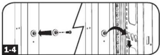
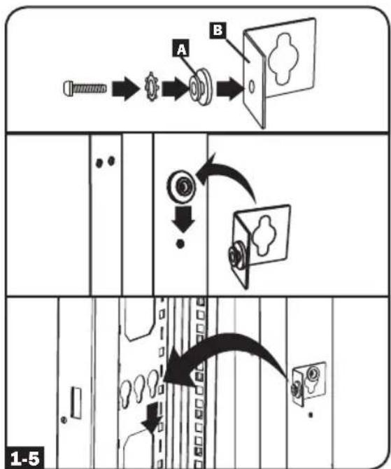
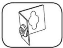
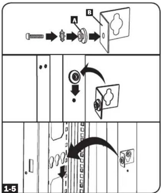
To install the PDU with its outlets facing the rear of the rack, use the included PDUMVROTATEBRKT accessory. First, attach the mounting button A to the V-shaped bracket B using the included screw and washer. Then, use the button-mount slot to attach the bracket to the PDU and the mounting button to attach the PDU to the rack. The bracket effectively repositions the mounting brackets allowing for the PDU outlets to face the rear of the rack.


flowchart
graph TD
    A["Start"] --> B["Reinact"]
    B --> C["Close"]
    C --> D["Shield"]
    D --> E["Shrinker"]
    E --> F["Shutter"]
    F --> G["Shield"]
    G --> H["Shrinker"]
    H --> I["Shutter"]
    I --> J["Shield"]
    J --> K["Shrinker"]
    K --> L["Shutter"]
    L --> M["Shield"]
    M --> N["Shrinker"]
    N --> O["Shutter"]
    O --> P["Shield"]
    P --> Q["Shrinker"]
    Q --> R["Shutter"]
    R --> S["Shield"]
    S --> T["Shrinker"]
    T --> U["Shutter"]
    U --> V["Shield"]
    V --> W["Shrinker"]
    W --> X["Shutter"]
    X --> Y["Shield"]
Installation
Connecting the PDU
2-1 Each model is equipped with 1 of 8 different input plugs.


L15-20P L15-30P L21-20P L21-30P L22-30P Hubbell CS8365C

IEC 309
30A Blue
(3P + E)

IEC 309
60A Blue
(3P + E)

IEC 309
32A Red
(3P + N + E)

IEC 309
63A Red
(3P + N + E)
| 208V Monitored Models Input Plug | Max Input Amps (Limited by Input Cord and Plug) | Input Voltage Range | Output Voltage Range | Breakers | Cord Length | Outlets | |
| PDU3EVN3L2130 L21-30P 24A 208V 208V | 3 x Double Pole, 20A Branch-Rated | 3 ft. (0.9 m) | 36 x C13; 6 x C19; 3 x 5-15/20R | ||||
| PDU3EVN10L2130 L21-30P 24A 208V 208V | 3 x Double Pole, 20A Branch-Rated | 10 ft. (3 m) | 36 x C13; 6 x C19; 3 x 5-15/20R | ||||
| PDU3EVN3L2120 L21-20P 16A 208V 208V N/A | 3 ft. (0.9 m) | 42 x C13; 6 x C19 | |||||
| PDU3EVN6L2120 L21-20P 16A 208V 208V N/A | 6 ft. (1.8 m) | 42 x C13; 6 x C19 | |||||
| PDU3EVN10L2120 L21-20P 16A 208V 208V N/A | 10 ft. (3 m) | 42 x C13; 6 x C19 | |||||
| PDU3EVN6L2130 L21-30P 24A 208V 208V | 3 x Double Pole, 20A Branch-Rated | 6 ft. (1.8 m) | 36 x C13; 6 x C19; 3 x 5-15/20R | ||||
| 208V Switched Models Input Plug | Max Input Amps (Limited by Input Cord and Plug) | Input Voltage Range | Output Voltage Range | Breakers | Cord Length | Outlets | |
| PDU3EVSR6G60A | IEC 309 60A Blue (3P + E); IP44 | 45A 208V | 208V | 6 x Low-Profile with Safety Lock, Double Pole, Magnetic, Branch-Rated | 6 ft. (1.8 m) | 6 x C13; 12 x C19 | |
| PDU3EVSR6H50A Hubbell CS8365C 40A 208V 208V | 6 x Low-Profile with Safety Lock, Double Pole, Magnetic, Branch-Rated | 6 ft. (1.8 m) | 6 x C13; 12 x C19 | ||||
| 200 - 240V Monitored Models Input Plug | Max Input Amps (Limited by Input Cord and Plug) | Input Voltage Range | Output Voltage Range | Breakers | Cord Length | Outlets | |
| PDU3EVN6G30B | IEC 309 30A Blue (3P + E); IP44 | 24A | 200-240V | 200-240V | 3 x Double Pole, 20A Branch-Rated | 6 ft. (1.8 m) | 42 x C13; 6 x C19 |
| PDU3EVN10G30B | IEC 309 30A Blue (3P + E); IP44 | 24A | 200-240V | 200-240V | 3 x Double Pole, 20A Branch-Rated | 10 ft. (3 m) | 42 x C13; 6 x C19 |
Installation
| 200 - 240V Monitored Models Input Plug | Max Input Amps (Limited by Input Cord and Plug) | Input Voltage Range | Output Voltage Range | Breakers | Cord Length | Outlets | |
| PDU3EVN3G60B | IEC 309 60A Blue (3P + E); IP44 | 35A | 200-240V | 200-240V | 3 x Double Pole, 20A Branch-Rated | 3 ft. (0.9 m) | 42 x C13; 6 x C19 |
| PDU3EVN6G60B | IEC 309 60A Blue (3P + E); IP44 | 35A | 200-240V | 200-240V | 3 x Double Pole, 20A Branch-Rated | 6 ft. (1.8 m) | 42 x C13; 6 x C19 |
| PDU3EVN10G60B | IEC 309 60A Blue (3P + E); IP44 | 35A | 200-240V | 200-240V | 3 x Double Pole, 20A Branch-Rated | 10 ft. (3 m) | 42 x C13; 6 x C19 |
| PDU3EVN3H50B Hubbell CS8365C 35A | 200-240V | 200-240V | 3 x Double Pole, 20A Branch-Rated | 3 ft. (0.9 m) | 42 x C13; 6 x C19 | ||
| PDU3EVN6H50B Hubbell CS8365C 35A | 200-240V | 200-240V | 3 x Double Pole, 20A Branch-Rated | 6 ft. (1.8 m) | 42 x C13; 6 x C19 | ||
| PDU3EVN6H50BA Hubbell CS8365C 35A | 200-240V | 200-240V | 3 x Double Pole, 20A Branch-Rated | 6 ft. (1.8 m) | 30 x C13; 12 x C19 | ||
| PDU3EVN10H50B Hubbell CS8365C 35A | 200-240V | 200-240V | 3 x Double Pole, 20A Branch-Rated | 10 ft. (3 m) | 42 x C13; 6 x C19 | ||
| PDU3EVN3L1520 L15-20 16A | 200-240V | 200-240V | — | 3 ft. (0.9 m) | 42 x C13; 6 x C19 | ||
| PDU3EVN6L1520 L15-20 16A | 200-240V | 200-240V | — | 6 ft. (1.8 m) | 42 x C13; 6 x C19 | ||
| PDU3EVN10L1520 L15-20 16A | 200-240V | 200-240V | — | 10 ft. (3 m) | 42 x C13; 6 x C19 | ||
| PDU3EVN3L1530B L15-30P 24A | 200-240V | 200-240V | 3 x Double Pole, 20A Branch-Rated | 3 ft. (0.9 m) | 42 x C13; 6 x C19 | ||
| PDU3EVN6L1530B L15-30P 24A | 200-240V | 200-240V | 3 x Double Pole, 20A Branch-Rated | 6 ft. (1.8 m) | 42 x C13; 6 x C19 | ||
| PDU3EVN10L1530B L15-30P 24A | 200-240V | 200-240V | 3 x Double Pole, 20A Branch-Rated | 10 ft. (3 m) | 42 x C13; 6 x C19 | ||
| PDU3EVN3L2130B L21-30P 24A | 200-240V | 200-240V | 3 x Double Pole, 20A Branch-Rated | 3 ft. (0.9 m) | 42 x C13; 6 x C19 | ||
| PDU3EVN6L2130B L21-30P 24A | 200-240V | 200-240V | 3 x Double Pole, 20A Branch-Rated | 6 ft. (1.8 m) | 42 x C13; 6 x C19 | ||
| PDU3EVN10L2130B L21-30P 24A | 200-240V | 200-240V | 3 x Double Pole, 20A Branch-Rated | 10 ft. (3 m) | 42 x C13; 6 x C19 | ||
| PDU3EVN6G60C | IEC 309 60A Blue (3P + E); IP44 | 45A | 200-240V | 200-240V | 6 x Low-Profile with Safety Lock, Double Pole, Magnetic, Branch-Rated | 6 ft. (1.8 m) | 36 x C13 |
Installation
| 200-240V Switched Models Input Plug | Max Input Amps (Limited by Input Cord and Plug) | Input Voltage Range | Output Voltage Range Breakers | Cord Length | Outlets | |
| PDU3EVSR6H50 Hubbell CS8365C 35A | 200-240V | 200-240V | 3 x Double Pole, 20A Branch-Rated | 6 ft. (1.8 m) | ||
| PDU3EVSR10H50 Hubbell CS8365C 35A | 200-240V | 200-240V | 3 x Double Pole, 20A Branch-Rated | 10 ft. (3 m) | ||
| PDU3EVSR6L1530 L15-30P 24A | 200-240V | 200-240V | 3 x Double Pole, 20A Branch-Rated | 6 ft. (1.8 m) | ||
| PDU3EVSR10L1530 L15-30P 24A | 200-240V | 200-240V | 3 x Double Pole, 20A Branch-Rated | 10 ft. (3 m) | ||
| PDU3EVSR6L2130 L21-30P 24A | 200-240V | 200-240V | 3 x Double Pole, 20A Branch-Rated | 6 ft. (1.8 m) | ||
| PDU3EVSR10L2130 L21-30P 24A | 200-240V | 200-240V | 3 x Double Pole, 20A Branch-Rated | 10 ft. (3 m) | ||
| PDU3EVSR6H50 Hubbell CS8365C 35A | 200-240V | 200-240V | 3 x Low Profile with Safety Lock, Double Pole, Magnetic, Branch-Rated | 6 ft. (1.8 m) | ||
| PDU3EVSR6L2130 L21-30P 24A | 200-240V | 200-240V | 3 x Low Profile with Safety Lock, Double Pole, Magnetic, Branch-Rated | 6 ft. (1.8 m) | ||
| PDU3EVSR6L2120 L21-20P 16A | 200-240V | 200-240V | — | 6 ft. (1.8 m) | ||
| PDU3EVSR6L2120 L21-20P 16A | 200-240V | 200-240V | — | 6 ft. (1.8 m) | ||
| PDU3EVSR6L1520 L15-20P 16A | 200-240V | 200-240V | — | 6 ft. (1.8 m) | ||
| 380-415V Monitored Models Input Plug | Max Input Amps (Limited by Input Cord and Plug) | Input Voltage Range | Output Voltage Range Breakers | Cord Length | Outlets | |
| PDU3XEVN6G20 | IEC 309 20A Red (3P + N + E); IP44 | 16A | 380-415V | 380-415V | — | 6 ft. (1.8 m) |
| 380-415V Switched Models Input Plug | Max Input Amps (Limited by Input Cord and Plug) | Input Voltage Range | Output Voltage Range Breakers | Cord Length | Outlets | |
| PDU3XEVSR6G20 | IEC 309 20A Red (3P + N + E); IP44 | 16A | 380-415V | 380-415V | — | 6 ft. (1.8 m) |
| PDU3XEVSR6G30A | IEC 309 32A Red (3P + N + E); IP44 | 24A | 380-415V | 380-415V | 6 x Low-Profile with Safety Lock, Single Pole, Magnetic, Branch-Rated | 6 ft. (1.8 m) |
Installation
| 380 - 415VSwitched Models Input Plug | Max Input Amps (Limited by Input Cord and Plug) | Input Voltage Range | Output Voltage Range | Breakers | Cord Length | Outlets | |
| PDU3XEVSR6G30B | IEC 309 32A Red(3P + N + E); IP44 | 24A | 380-415V | 380-415V | 6 x Double Pole, 20A Branch-Rated | 6 ft.(1.8 m) | 24 x C13; 6 x C19 |
| PDU3XEVSR6G32A | IEC 309 32A Red(3P + N + E); IP44 | 32A | 380-415V | 380-415V | 6 x Low-Profile with Safety Lock, Single Pole, Magnetic, Branch-Rated | 6 ft.(1.8 m) | 12 x C13; 12 x C19 |
| PDU3XEVSR6G32B | IEC 309 32A Red(3P + N + E); IP44 | 32A | 380-415V | 380-415V | 6 x Double Pole, 20A Branch-Rated | 6 ft.(1.8 m) | 24 x C13; 6 x C19 |
| PDU3XEVSR6G60A | IEC 309 63A Red(3P + N +E); IP44 | 35A | 380-415V | 380-415V | 6 x Low-Profile with Safety Lock, Single Pole, Magnetic, Branch-Rated | 6 ft.(1.8 m) | 12 x C13; 12 x C19 |
| PDU3XEVSR6G60B | IEC 309 63A Red(3P + N +E); IP44 | 35A | 380-415V | 380-415V | 6 x Double Pole, 20A Branch-Rated | 6 ft.(1.8 m) | 24 x C13; 6 x C19 |
| PDU3XEVSR6G63A | IEC 309 63A Red(3P + N +E); IP44 | 40A | 380-415V | 380-415V | 6 x Low-Profile with Safety Lock, Single Pole, Magnetic, Branch-Rated | 6 ft.(1.8 m) | 12 x C13; 12 x C19 |
| PDU3XEVSR6G63B | IEC 309 63A Red(3P + N +E); IP44 | 40A | 380-415V | 380-415V | 6 x Double Pole, 20A Branch-Rated | 6 ft.(1.8 m) | 24 x C13; 6 x C19 |
| PDU3XEVSR6L230B | L22-30P 24A | 380-415V | 380-415V | 6 x Double Pole, 20A Branch-Rated | 6 ft.(1.8 m) | 24 x C13; 6 x C19 | |
| PDU3XEVSR6L2230 | L22-30P 24A | 380-415V | 380-415V | 6 x Low-Profile with Safety Lock, Single Pole, Magnetic, Branch-Rated | 6 ft.(1.8 m) | 12 x C13; 12 x C19 | |
| PDU3XEVSRHWA Hardware 40A | 380-415V | 380-415V | 6 x Low-Profile with Safety Lock, Single Pole, Magnetic, Branch-Rated | N/A 12 | x C13; 12 x C19 | ||
| PDU3XEVSRHWB Hardware 40A | 380-415V | 380-415V | 6 x Double Pole, 20A Branch-Rated | N/A 24 | x C13; 6 x C19 | ||
Installation
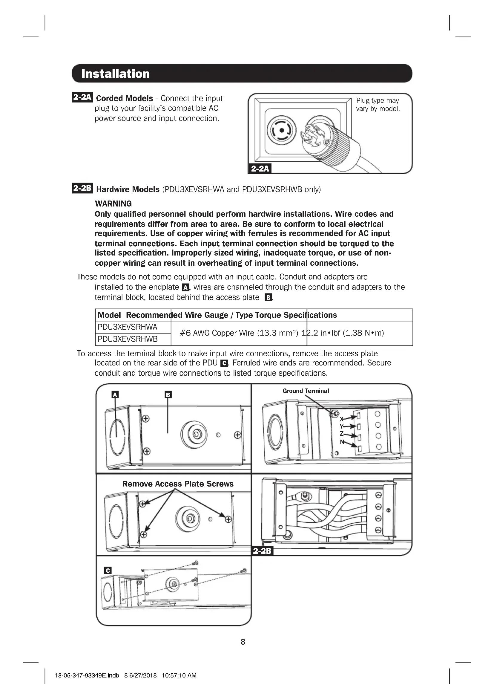
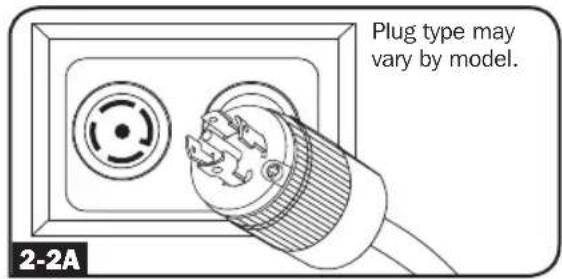
2-2A
Corded Models - Connect the input plug to your facility's compatible AC power source and input connection.
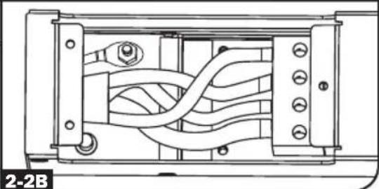
2-2B
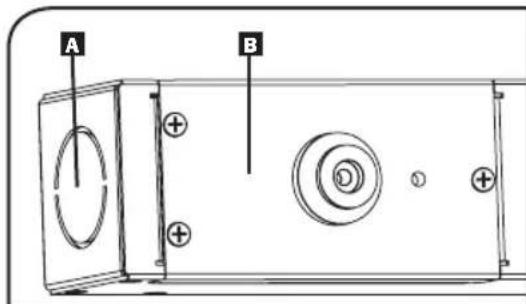
Hardware Models (PDU3XEVSRHWA and PDU3XEVSRHWB only)
WARNING
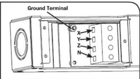
Only qualified personnel should perform hardwire installations. Wire codes and requirements differ from area to area. Be sure to conform to local electrical requirements. Use of copper wiring with ferrules is recommended for AC input terminal connections. Each input terminal connection should be torqued to the listed specification. Improperly sized wiring, inadequate torque, or use of non-copper wiring can result in overheating of input terminal connections.
These models do not come equipped with an input cable. Conduit and adapters are installed to the endplate A, wires are channeled through the conduit and adapters to the terminal block, located behind the access plate B.
| Model Recommended Wire Gauge / Type Torque Specifications | |
| PDU3XEVSRHWA | #6 AWG Copper Wire (13.3 mm2) 12.2 in•lbf (1.38 N•m) |
| PDU3XEVSRHWB | |
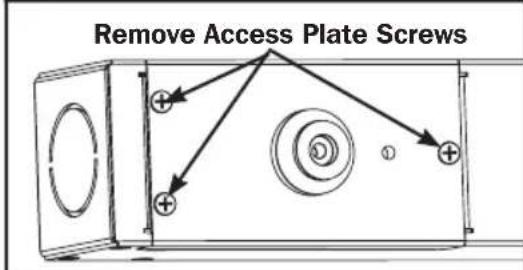
To access the terminal block to make input wire connections, remove the access plate located on the rear side of the PDU C. Ferruled wire ends are recommended. Secure conduit and torque wire connections to listed torque specifications.
natural_image
Technical diagram of a mechanical or electrical component with internal wiring and mounting brackets (no text or symbols)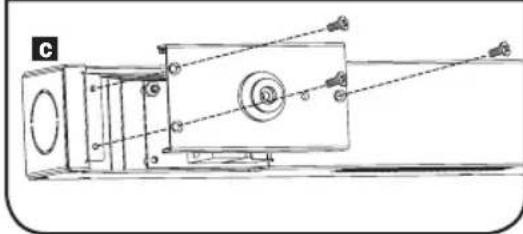
natural_image
Technical line drawing of a mechanical device with no visible text or symbolsInstallation
2-3
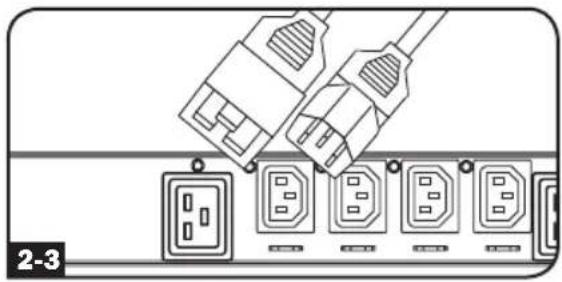
Connect your equipment's input plugs to the appropriate outlets on the PDU. The LED near each outlet illuminates when the outlet is ready to distribute live AC power.
Note: It is recommended that you do not connect a live load to the PDU. If the load you intend to connect has an ON/OFF switch, please turn the switch to OFF prior to connection.
natural_image
Diagram of a cable connector with multiple socket ports and connectors, no text or symbols present2-4
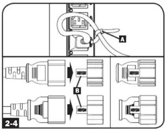
Optional Cord Retention Procedure
Option 1: Use the bridge lances located near each receptacle to retain power cords. Tie each equipment power cord to a bridge lance by looping the cord and securing it with one of the included cable ties A. Make sure each cord can be unplugged from the PDU without removing the cable tie.
Option 2: Use the included C14 and C20 plastic sleeves to secure plugs to receptacles. Attach the sleeve to the plug, making sure that the pull tabs B remain outside the plug and that the fit is secure. To unplug equipment properly, use the pull tabs to remove the plug and sleeve from the receptacle.
Networking the PDU
Your PDU can receive IP address assignments via DHCP server (dynamic) or static (manual) addressing methods. See the LX Platform User's Guide for an explanation of these methods. You can find the guide by going to www.triplite.com/support and typing LX Platform in the search field. If you are uncertain which method to use, contact your network administrator for assistance before continuing the configuration process.
Note: The MAC address of the PDU (12-digit string in this format: 000667xxxxxx) is printed on a label attached to the PDU enclosure.
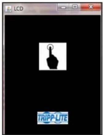
LCD Touchscreen
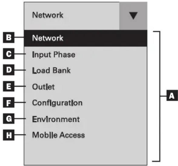
A Main Menu: Use the ▼ on the touchscreen to toggle between the main menu and the previously selected panel. Available options will vary based on the PDU and peripherals.
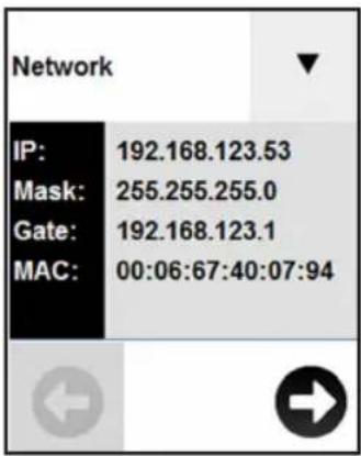
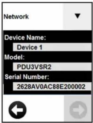
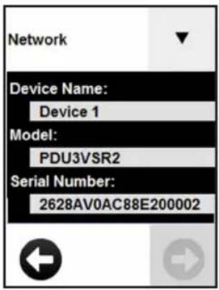
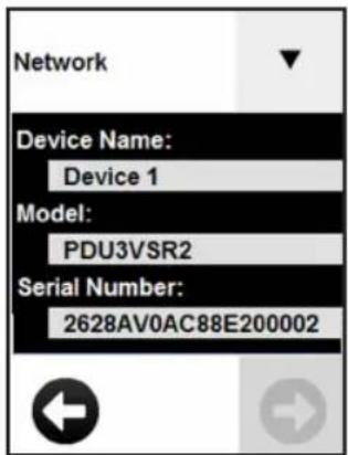
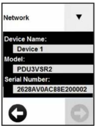
B Network: Displays the IP address, Subnet Mask, Gateway, MAC Address, Device Name, Model and Serial Number.
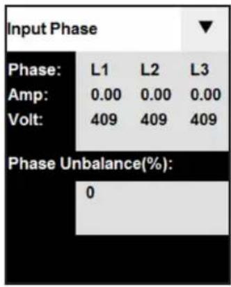
C Input Phase: Displays the amperage and voltage for each phase, as well as the Unbalanced Load %.
D Load Bank: Displays the total amperage, wattage and voltage for each load bank as well as the total power in Watts.
E Outlet: Displays the amperage and wattage per outlet.
F Configuration: Displays configurable settings for the LCD touchscreen.
G Environment: Displays the data and status of any EnviroSense2 (E2) modules connected to the PDU. The information shown will vary depending on the E2 model (E2MT, E2MTDI, E2MTDO, E2MTHDI). Parameters include temperature, RH% (relative humidity), and the status of input and output dry contacts (open or closed).
Mobile Access: Generates a unique QR code to view the PDU's details on a mobile device.
Using the LCD Touchscreen
Scrolling Through LCD Touchscreen Options
Network
Press Network on the drop down menu to view the PDU network details. Press the ▼ and ▶ move between screens. Details displayed include the IP address (IP), Subnet Mask (Mask), Gateway (Gate), MAC Address (MAC), Device Name, Model and Serial Number. Press ▼ to go back to the main menu.
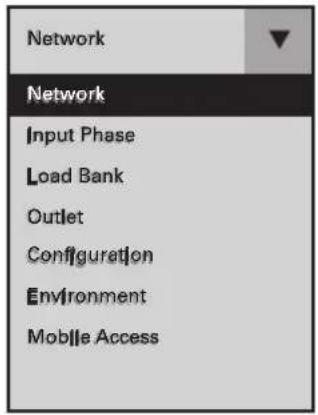
After the system initializes, the Network panel will appear. Use ▼ on the touchscreen to display the menu. Touch the desired menu option to select. Available options will vary based on the PDU and peripherals.
Input Phase
Press Input Phase on the drop down menu to view the status of each phase. The amperage and voltage for L1, L2 and L3 will be displayed, as well as the Phase Unbalance %.
| INPUT PHASE REPORTED LCD REFERENCE | |
| L1 - L2 L1 | |
| L2 - L3 L2 | |
| L3 - L1 L3 | |
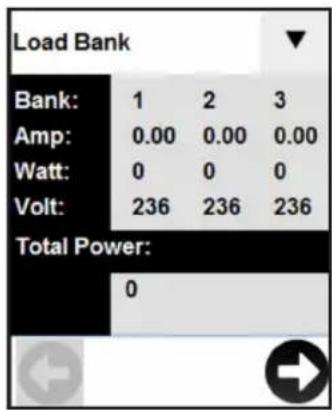
Load Bank
Press Load Bank on the main menu to view the status of each of the PDU's load banks. The bank number will be displayed in addition to total amperage, wattage and voltage per bank, as well as the total power in Watts. Use 📋 and 🔺 scroll through the available banks.
| LOAD BANK LCD REFERENCE | |
| Bank 1 1 | |
| Bank 2 2 | |
| Bank 3 3 | |
Using the LCD Touchscreen
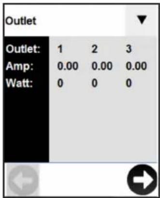
Outlet
Press Outlet on the main menu to view the status of each PDU outlet. The outlet number will be displayed along with the amperage and wattage of each individual outlet. Use 📋 and 📍 scroll through all of the outlets.
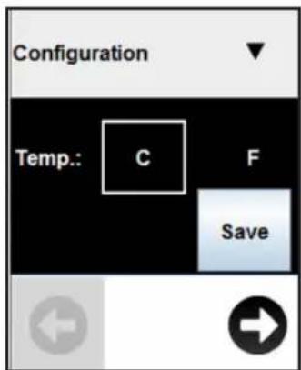
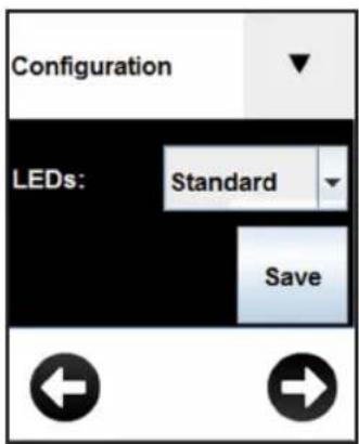
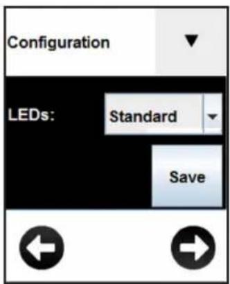
Configuration
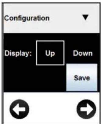
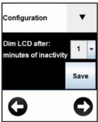
Press Configuration on the drop down menu to change the PDU settings. Configurable settings include temperature, display orientation, LCD brightness, LED settings and a display dimming option.
Note: Any changes must be saved in order for the newly configured settings to remain.


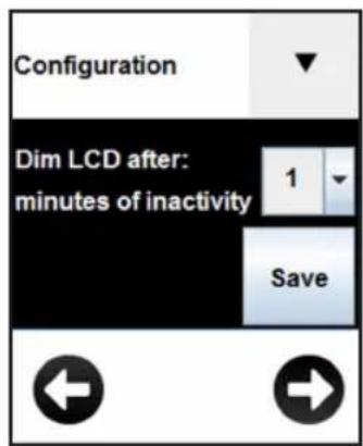
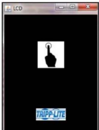
Screensaver
The screensaver will display after the configured number of minutes of inactivity.
Note: If the display is dimmed, any touch to the screen will return the LCD screen to its previous brightness prior to dimming.
Using the LCD Touchscreen
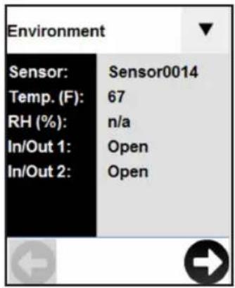
Environment
Press Environment on the drop down menu to view a panel for each E2 module connected to the PDU. Use the and to view other E2 modules.
Note: The available information will vary based on the E2 module.

Mobile Access
A unique QR code is generated each time the Mobile Access panel is accessed. Make sure the PDU and mobile device are on the same network. Scan the code with a QR code reader on your mobile device for read-only access to the PowerAlert Device Manager.
When accessed through the QR code, PowerAlert Device Manager is in read-only mode. To access the PDU with full read/write control from a mobile device on the same network, enter the device's IP address in your browser and login to PowerAlert Device Manager as a user with read/write credentials.
Note: If the Mobile Access panel is blank, a QR code will not be generated until a valid static or dynamic IP address is assigned to the PDU.
Features
natural_image
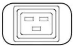
Simple line drawing of an electrical outlet with three slots (no text or symbols)C13 C19
natural_image
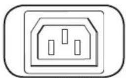
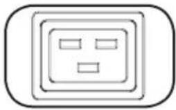
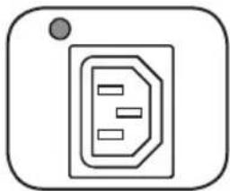
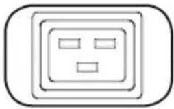
Simple line drawing of a wall socket with three slots, enclosed in a rounded square frame (no text or symbols)Outlets: During normal operation, the outlets distribute AC power to connected equipment.
natural_image
Simple line icon of a document with a gray dot above it, no text or symbols present.Outlet Status LED: Once the unit is powered on, each outlet individually ramps up and each Outlet Status LED will illuminate when the associated outlet is ready to distribute live AC power.
| LED Configuration | LED Color Outlet | Status Description | |
| Standard^1 | Off Off Outlet power is absent | ||
| Green On Circuit breaker is on – Outlet power is present | |||
| Yellow On | Outlet's current has exceeded 80% of the outlet current rating – Outlet power is present | ||
| Red Off | Outlet's voltage is below the Low Voltage threshold – Outlet power is absent | ||
| Red Flashing Off Circuit breaker has tripped – Outlet power is absent | |||
| Alternate | Off Off Outlet power is absent | ||
| Red On Circuit breaker is on – Outlet power is present | |||
| Red Flashing On | Outlet's current has exceeded 80% of the outlet current rating – Outlet power is present | ||
| Green Off Outlet is disabled – Outlet power is absent | |||
| Green Flashing Off Circuit breaker has tripped – Outlet power is absent | |||
1 This is the default configuration.
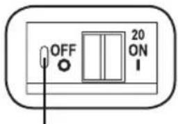
Push-to-Reset Guard
Circuit Breaker (Select Models): There are 3 Load Banks, each protected by a circuit breaker. If the connected equipment load exceeds the Maximum Load Rating for those banks of the PDU, the circuit breaker will trip. Disconnect excess load and reset the breaker.
Note: Each breaker comes equipped with a push-to-reset guard to prevent accidental breaker tripping. To turn off the breaker, insert a flathead screwdriver into the reset slot.
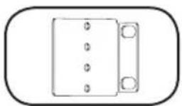
Mounting Brackets: Use these brackets as an alternate PDU mounting method.
natural_image
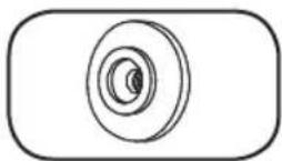
Simple line drawing of a door with a handle and screw base (no text or symbols)Mounting Buttons: Located on the back side of the PDU, the pre-installed buttons are used for toolless mounting.
Note: Four additional mounting buttons are included for alternate rack styles.
PDUMVROTATEBRKT Mounting Accessory: Use these L-shaped brackets to mount the PDU with its outlets facing the rear of the rack.
Features
natural_image
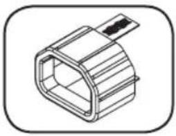
Technical line drawing of a mechanical component with no visible text or symbolsC14 Plug-Lock Inserts (Optional): Use the included C14 plug-lock inserts to secure plugs to C13 receptacles. Attach the sleeve to the plug making sure the pull tabs remain outside the plug and that the fit is secure. To unplug equipment properly, use the pull tabs to remove the plug and insert from the receptacle.
natural_image
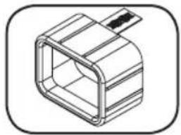
Isometric line drawing of a rectangular mechanical component with a protruding rod (no text or symbols)C20 Plug-Lock Inserts (Optional): Use the included C20 plug-lock inserts to secure plugs to C19 receptacles. Attach the sleeve to the plug making sure the pull tabs remain outside the plug and that the fit is secure. To unplug equipment properly, use the pull tabs to remove the plug and insert from the receptacle.

Ground Screw: Use this to connect any equipment that requires a chassis ground.
Network Interface
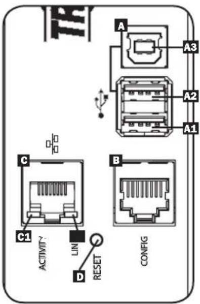
A USB Ports: The two USB-A ports A1 and A2 connect to one of four different Tripp Lite EnviroSense2 (E2) environmental sensors* for remote temperature or temperature/humidity monitoring (up to three E2 sensors can be daisy-chained). The USB-B port A3 is used for initial network interface configuration and direct console access from a laptop**.
*USB-A ports are designed for use with E2 modules only. Do not connect other USB devices to these ports.
**Only 2 of 3 USB ports can be used simultaneously. For example: 2 USB-A (A1 and A2), or 1 USB-B and the lower USB-A port (A3 and A1); the upper USB-A port A2 cannot connect with the USB-B port A3.
B RJ45 Configuration Port: This port can also be used to configure the network interface and command line access from a laptop.
C Ethernet Port: Use this RJ45 jack to connect the PDU to the network with a standard Ethernet patch cable. The behavior of the Activity LED ⬤1 and Link LED ⬤2 is shown in the table below. This port is not compatible with PoE (Power Over Ethernet) applications.
| LED Function LED Color Off On Flashing | |||
| Activity Green | No Activity — Activity | ||
| Link Yellow No Link | Link (Any Speed) | — | |
SNMP Reset Button: The reset button is recessed. Use a paper clip or other suitable object to press the reset button for 3 seconds to reboot the PDU's network interface. Rebooting the network interface will not erase network settings or interrupt AC power. Press and hold the reset button for 20 seconds to restore the PDU's network interface to its factory default settings. Restoring to the factory default will erase all previously saved data—including network settings—without interrupting AC power.
Configuration and Operation
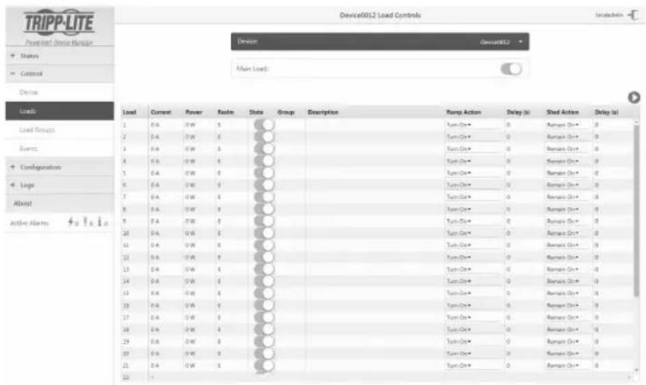
Remote Monitoring and Control
The PDU can be monitored and controlled remotely via Web browser, telnet and SNMP-based Network Management Systems. For more information about configuration and operation of the PDU via the PowerAlert Device Manger, refer to the LX Platform User's Guide, which can be found by going to www.tripplite.com/support and typing LX Platform in the search field.
Service
Your Tripp Lite product is covered by the warranty described in this manual. A variety of Extended Warranty and On-Site Service Programs are also available from Tripp Lite. For more information on service, visit www.tripplite.com/support. Before returning your product for service, follow these steps:
- Review the installation and operation procedures in this manual to ensure that the service problem does not originate from a misreading of the instructions.
- If the problem continues, do not contact or return the product to the dealer. Instead, visit www.tripplite.com/support.
- If the problem requires service, visit www.triplite.com/support and click the Product Returns link. From here you can request a Returned Material Authorization (RMA) number, which is required for service. This simple on-line form will ask for your unit's model and serial numbers, along with other general purchaser information. The RMA number, along with shipping instructions will be emailed to you. Any damages (direct, indirect, special or consequential) to the product incurred during shipment to Tripp Lite or an authorized Tripp Lite service center is not covered under warranty. Products shipped to Tripp Lite or an authorized Tripp Lite service center must have transportation charges prepaid. Mark the RMA number on the outside of the package. If the product is within its warranty period, enclose a copy of your sales receipt. Return the product for service using an insured carrier to the address given to you when you request the RMA.
Warranty and Product Registration
2- YEAR LIMITED WARRANTY
Seller warrants this product, if used in accordance with all applicable instructions, to be free from original defects in material and workmanship for a period of 2 years from the date of initial purchase. If the product should prove defective in material or workmanship within that period, Seller will repair or replace the product, in its sole discretion. Service under this Warranty can only be obtained by your delivering or shipping the product (with all shipping or delivery charges prepaid) to: Tripp Lite, 1111 W. 35th Street, Chicago, IL 60609 USA. Seller will pay return shipping charges. Visit www.triplite.com/support before sending any equipment back for repair.
THIS WARRANTY DOES NOT APPLY TO NORMAL WEAR OR TO DAMAGE RESULTING FROM ACCIDENT, MISUSE, ABUSE OR NEGLECT. SELLER MAKES NO EXPRESS WARRANTIES OTHER THAN THE WARRANTY EXPRESSLY SET FORTH HEREIN. EXCEPT TO THE EXTENT PROHIBITED BY APPLICABLE LAW, ALL IMPLIED WARRANTIES, INCLUDING ALL WARRANTIES OF MERCHANTABILITY OR FITNESS, ARE LIMITED IN DURATION TO THE WARRANTY PERIOD SET FORTH ABOVE; AND THIS WARRANTY EXPRESSLY EXCLUDES ALL INCIDENTAL AND CONSEQUENTIAL DAMAGES. (Some states do not allow limitations on how long an implied warranty lasts, and some states do not allow the exclusion or limitation of incidental or consequential damages, so the above limitations or exclusions may not apply to you. This Warranty gives you specific legal rights, and you may have other rights which vary from jurisdiction to jurisdiction).
WARNING: The individual user should take care to determine prior to use whether this device is suitable, adequate or safe for the use intended. Since individual applications are subject to great variation, the manufacturer makes no representation or warranty as to the suitability or fitness of these devices for any specific application.
PRODUCT REGISTRATION
Visit www.triplite.com/warranty today to register your new Tripp Lite product.You'll be automatically entered into a drawing for a chance to win a FREE Tripp Lite product!*
* No purchase necessary. Void where prohibited. Some restrictions apply. See website for details.
FCC Notice, Class A
This device complies with part 15 of the FCC Rules. Operation is subject to the following two conditions: (1) This device may not cause harmful interference, and (2) this device must accept any interference received, including interference that may cause undesired operation.
Note: This equipment has been tested and found to comply with the limits for a Class A digital device, pursuant to part 15 of the FCC Rules. These limits are designed to provide reasonable protection against harmful interference when the equipment is operated in a commercial environment. This equipment generates, uses, and can radiate radio frequency energy and, if not installed and used in accordance with the instruction manual, may cause harmful interference to radio communications. Operation of this equipment in a residential area is likely to cause harmful interference in which case the user will be required to correct the interference at his own expense. The user must use shielded cables and connectors with this equipment. Any changes or modifications to this equipment not expressly approved by Tripp Lite could void the user's authority to operate this equipment.
Regulatory Compliance Identification Numbers
For the purpose of regulatory compliance certifications and identification, your Tripp Lite product has been assigned a unique series number. The series number can be found on the product nameplate label, along with all required approval markings and information. When requesting compliance information for this product, always refer to the series number. The series number should not be confused with the marketing name or model number of the product.
WEEE Compliance Information for Tripp Lite Customers and Recyclers (European Union)

Under the Waste Electrical and Electronic Equipment (WEEE) Directive and implementing regulations, when customers buy new electrical and electronic equipment from Tripp Lite they are entitled to:
- Send old equipment for recycling on a one-for-one, like-for-like basis (this varies depending on the country)
- Send the new equipment back for recycling when this ultimately becomes waste
Tripp Lite has a policy of continuous improvement. Specifications are subject to change without notice.


1111 W. 35th Street, Chicago, IL 60609 USA • www.tripplite.com/support
natural_image
Technical diagram showing two screws mounted on a vertical panel with dashed lines indicating alignment (no text or symbols)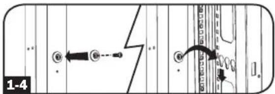
flowchart
graph TD
    A["Pinning Pin"] --> B["Assembly Step"]
    B --> C["Car Window"]
    C --> D["Door Opening"]
    D --> E["Back Cover"]
    style A fill:#f9f,stroke:#333
    style B fill:#ccf,stroke:#333
    style C fill:#cfc,stroke:#333
    style D fill:#fcc,stroke:#333
Instalación
Conexión del PDU

IEC 309
32A Rojo
(3P + N + T)

IEC 309
63A Rojo
(3P + N + T)
natural_image
Diagram of a network connection showing two connected power plugs and four output ports (no text or labels)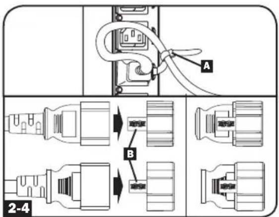
Red
Acceso por Móvil
natural_image
Simple line drawing of an electrical outlet with three slots (no text or symbols)C13 C19
natural_image
Simple line drawing of an electrical outlet with three slots and a central socket (no text or symbols)natural_image
Simple line icon of a device with a circular button and rectangular body, no text or symbols present.natural_image
Simple line drawing of a door with a handle and screw base (no text or symbols)natural_image
Isometric line drawing of a mechanical component with no text or symbolsnatural_image
Isometric line drawing of a 3D cube-shaped object with internal grid lines and a protruding rod (no text or symbols)1111 W. 35th Street, Chicago, IL 60609 USA • www.tripplite.com/support
natural_image
Diagram of a network switch connected to multiple ports (no text or symbols visible)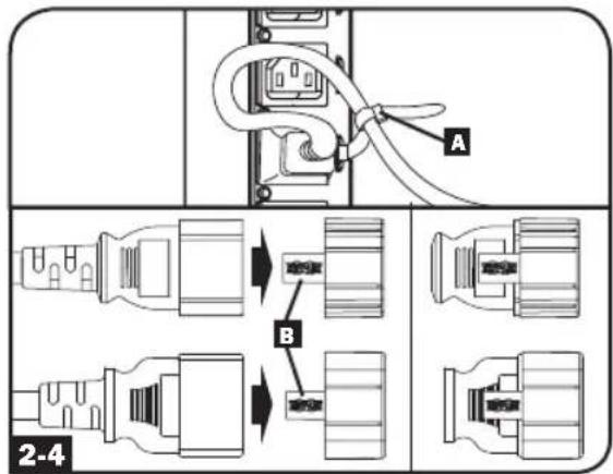
Réseau


Économiseur d'écran
Accès mobile
natural_image
Simple line drawing of an electrical outlet with three slots (no text or symbols)C13 C19
natural_image
Simple line drawing of a wall socket with three slots and two rectangular buttons (no text or symbols)natural_image
Simple line icon of a document with a gray dot above it, no text or symbols present.natural_image
Simple line drawing of a door with a handle and screw base (no text or symbols)natural_image
Technical line drawing of a mechanical component with no visible text or symbolsnatural_image
Isometric line drawing of a 3D rectangular component with internal structure (no text or symbols)Entretien
1111 W. 35th Street, Chicago, IL 60609 USA • www.tripplite.com/support
1111 W. 35th Street, Chicago, IL 60609 USA • www.tripplite.com/support
natural_image
Pure technical diagram showing a mechanical assembly with no text, numbers, or symbols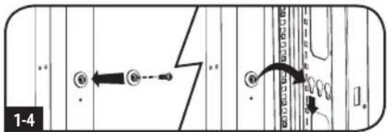

flowchart
graph TD
    A["Fastening"] --> B["Reinfection"]
    B --> C["Close-up of door"]
    C --> D["Reinjection"]
    D --> E["Reinjection with circular detail"]
    E --> F["Reinjection with crosshair detail"]
    F --> G["Reinjection with handbag detail"]
    G --> H["Reinjection with handbag detail"]
    H --> I["Reinjection with handbag detail"]
    I --> J["Reinjection with handbag detail"]
    J --> K["Reinjection with handbag detail"]
    K --> L["Reinjection with handbag detail"]
    L --> M["Reinjection with handbag detail"]
    M --> N["Reinjection with handbag detail"]
    N --> O["Reinjection with handbag detail"]
    O --> P["Reinjection with handbag detail"]
    P --> Q["Reinjection with handbag detail"]
    Q --> R["Reinjection with handbag detail"]
    R --> S["Reinjection with handbag detail"]
    S --> T["Reinjection with handbag detail"]
    T --> U["Reinjection with handbag detail"]
    U --> V["Reinjection with handbag detail"]
    V --> W["Reinjection with handbag detail"]
    W --> X["Reinjection with handbag detail"]
    X --> Y["Reinjection with handbag detail"]
    Y --> Z["Reinjection with handbag detail"]
Установка
Подключение PDU
natural_image
Technical line drawing of a mechanical device with no visible text or symbols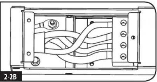
natural_image
Technical diagram of a mechanical or electrical component with internal wiring and mounting holes (no text or symbols)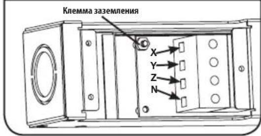
natural_image
Diagram of a network switch connected to multiple ports (no text or symbols visible)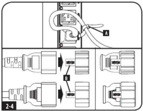
Network (Сеть)
other
| Category | Value | |---|---| | Bank: | 1 | | Amp: | 0.00 | | Watt: | 0 | | Volt: | 236 | | Total Power: | 0 |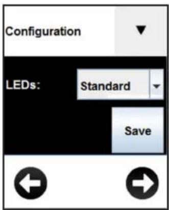


Экранная заставка
natural_image
Simple line drawing of an electrical outlet with three slots (no text or symbols)C13 C19
natural_image
Simple line drawing of an electrical outlet with three slots and two rectangular outlets (no text or symbols)natural_image
Simple line icon of a document with a circular dot above it, no text or symbols present.natural_image
Simple line drawing of a door with a cloud-like pattern on the front panel (no text or symbols)natural_image
Technical line drawing of a mechanical component with no visible text or symbolsnatural_image
Isometric line drawing of a 3D cube-shaped object with internal structure and a protruding rod (no text or symbols)1111 W. 35th Street, Chicago, IL 60609 USA • www.tripplite.com/support
18-05-347 93-349E_RevE
- 3-Phase Monitored & Switched 0U Power Distribution Units
- Important Safety Instructions
- SAVE THESE INSTRUCTIONS
- Installation
- Mounting the PDU
- Connecting the PDU
- 2-2A
- 2-2B
- WARNING
- 2-3
- 2-4
- Optional Cord Retention Procedure
- Networking the PDU
- LCD Touchscreen
- Using the LCD Touchscreen
- Scrolling Through LCD Touchscreen Options
- Network
- Input Phase
- Load Bank
- Outlet
- Configuration
- Screensaver
- Environment
- Mobile Access
- Features
- Network Interface
- Configuration and Operation
- Remote Monitoring and Control
- Service
- Warranty and Product Registration
- 2- YEAR LIMITED WARRANTY
- PRODUCT REGISTRATION
- FCC Notice, Class A
- Regulatory Compliance Identification Numbers
- WEEE Compliance Information for Tripp Lite Customers and Recyclers (European Union)
- Instalación
- Conexión del PDU
- Red
- Acceso por Móvil
- Réseau
- Économiseur d'écran
- Accès mobile
- Entretien
- Установка
- Подключение PDU
- Network (Сеть)
- Экранная заставка
Brand : Tripp Lite
Model : PDU3XEVSR6L230B
Category : Power strip