
FSWM1000 - Workbench BLACK & DECKER - Free user manual and instructions
Find the device manual for free FSWM1000 BLACK & DECKER in PDF.
| Product Type | Folding Workbench |
| Brand | Black & Decker |
| Model | FSWM1000 |
| Maximum Load Capacity | 160 kg (350 lb) |
| Main Material | Steel and Plastic |
| Approximate Weight | 18 kg |
| Unfolded Dimensions (approx) | 90 x 60 x 80 cm |
| Folded Dimensions (approx) | 90 x 60 x 15 cm |
| Number of Clamps | 2 Adjustable Clamps |
| Clamp Positions | Horizontal and Vertical |
| Lower Storage Shelf | Yes |
| Carrying Handle | Yes |
| Recommended Use | Home, DIY |
| Warranty | 2 years (domestic use) |
| Care and Cleaning | Mild detergent and damp cloth, do not immerse |
| Main Safety Instructions | Do not exceed 160 kg, balance loads, do not use as a ladder |
| Spare Parts and Repairability | Available through approved service centers or 1-800-544-6986 |
Frequently Asked Questions - FSWM1000 BLACK & DECKER
User questions about FSWM1000 BLACK & DECKER
0 question about this device. Answer the ones you know or ask your own.
Ask a new question about this device
Download the instructions for your Workbench in PDF format for free! Find your manual FSWM1000 - BLACK & DECKER and take your electronic device back in hand. On this page are published all the documents necessary for the use of your device. FSWM1000 by BLACK & DECKER.
USER MANUAL FSWM1000 BLACK & DECKER
THANK YOU FOR CHOOSING FIRESTORM! GO TO www.FIRESTORMTOOLS.COM/PRODUCTREGISTRATION TO REGISTER YOUR NEW PRODUCT.
BEFORE RETURNING THIS PRODUCT FOR ANY REASON PLEASE CALL 1-800-544-6986
BEFORE YOU CALL, HAVE THE FOLLOWING INFORMATION AVAILABLE, CATALOG No., TYPE No., AND DATE CODE. IN MOST CASES, A BLACK & DECKER REPRESENTATIVE CAN RESOLVE THE PROBLEM OVER THE PHONE. IF YOU HAVE A SUGGESTION OR COMMENT, GIVE US A CALL. YOUR FEEDBACK IS VITAL TO BLACK & DECKER.
SAVE THIS MANUAL FOR FUTURE REFERENCE.
VEA EL ESPANOL EN LA CONTRAPORTADA.
INSTRUCTIVO DE OPERACION, CENTROS DE SERVICIO Y POLIZA DE GARANTIA. ADVERTENCIA: LEASE ESTE INSTRUCTIVO ANTES DE USAR EL PRODUCTO.
IMPORTANT SAFETY INSTRUCTIONS
- Do not load with more than 350 lbs. (160kg). Do not leave heavy loads on work surface for extended periods of time.
- Do not apply an unbalanced load which could cause the workbench to tip over.
- Do not use the work center as a stepladder or standing platform. Do not use the lower platform as a step.
- Do not store workbench outdoors or in a damp location.
- Avoid applying excessive force when clamping with the supplied clamps.
- Be sure that the legs are fully open and the center support is in position and locked before use.
- When using a power tool with the workbench, follow the safety instructions in the tool's instruction manual.
- Do not mount or clamp power tools to any surface.
- Always wear safety glasses when operating power tools.
- Cutting or drilling into work surface may weaken supports, damaging tool or workbench.
- Caution required when using high temperature tools (heat guns, torch, solder, iron, etc.). May damage work surface and reduce clamping capability.
- Do not store flammable liquids on the workbench.
SAVE THESE INSTRUCTIONS FOR FUTURE USE
OPERATION
OPENING THE WORKBENCH
The FSWM1000 is packaged completely folded in the carton.
To open:
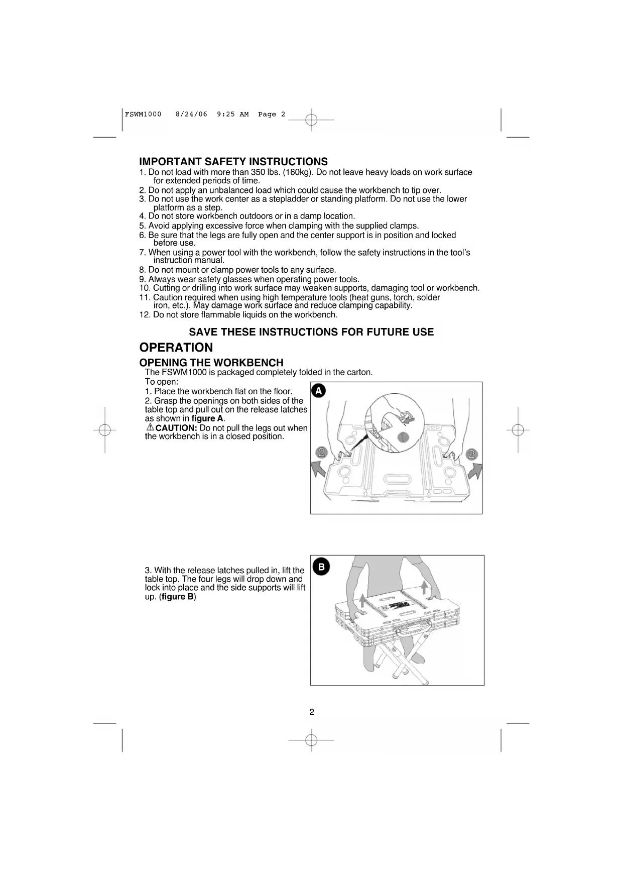
- Place the workbench flat on the floor.
- Grasp the openings on both sides of the table top and pull out on the release latches as shown in figure A.
CAUTION: Do not pull the legs out when the workbench is in a closed position.
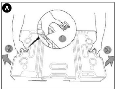
- With the release latches pulled in, lift the table top. The four legs will drop down and lock into place and the side supports will lift up. (figure B)
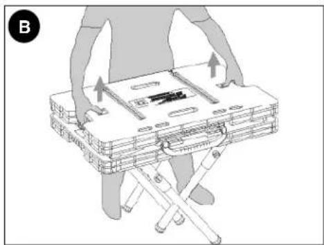
- To lock the side supports, push out from the inside until the support locks into position (figure C.) CAUTION: Risk of Unsafe Operation. Make sure all four legs and both side supports are locked in place.
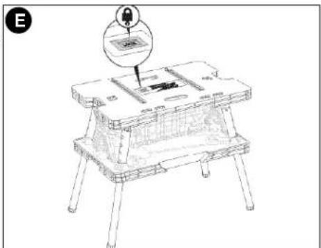
- After locking the side supports in place, lift the center support section by the carrying handle until you hear it "click" into place as shown in figure D.

- When the center support section is properly locked in position, the LOCK button shown in figure E will be visible. CAUTION: Risk of Unsafe Operation. Make sure the center support section is locked in place.
CLOSING THE WORKBENCH
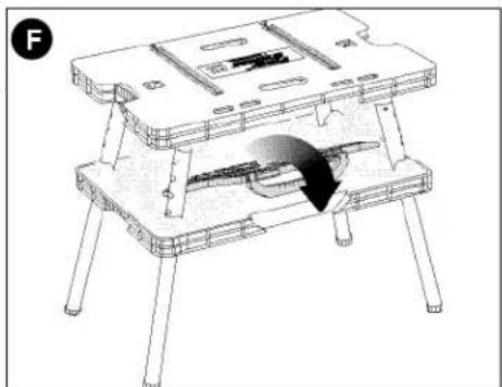
- Fold the center support section down and push in on the side supports to unlock them. (figure F)
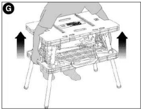
- Reach through the openings in the table top and grasp the lower section of the bench. Pull up on the lower section to begin collapsing the legs. (figure G)
- Lower the unit to the ground as shown in figure H.
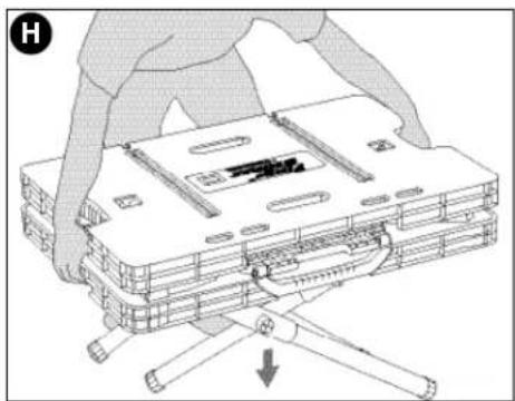
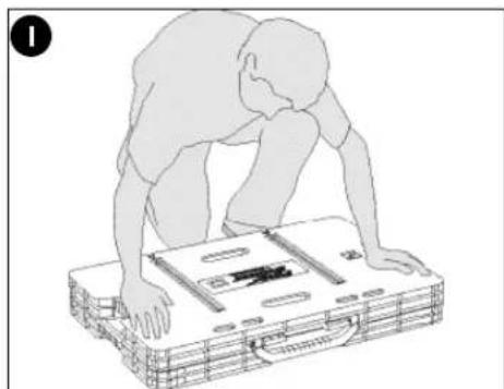
- Once the unit is flat on the ground, press down on the table top to place the unit into its fully closed position as shown in figure 1.
ADJUSTABLE CLAMPS
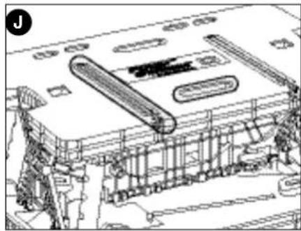
The two adjustable clamps can be used in both a vertical and horizontal mode. The long channels in the table top allow the clamps to be anchored in a stationary horizontal position. The shorter slots in the table top allow for the clamps to be used in a vertical position. (figure J). J1 through J6 illustrate how to use the clamps in both horizontal and vertical modes.
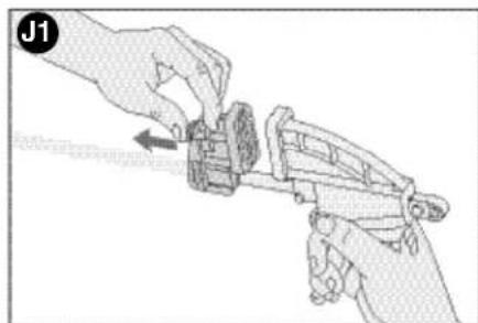
J1 - To expand the opening of the clamp jaws, press in on the release lever and move the jaw as shown. The jaw that is attached to the handle can also be moved in the same manner or by squeezing and releasing the front handle.
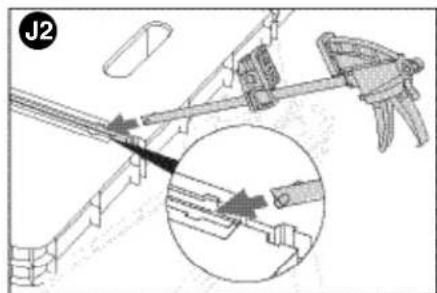
J2 - Line up the round post on the end of the clamp bar with the mating openings on both sides of the main slot in the tabletop as shown.
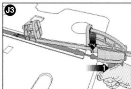
J3 - To lock the clamp in a horizontal position, squeeze the front handle and line up the round protruding tabs with the mating openings in the tabletop (behind the openings mentioned in J2 above).
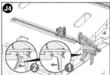
J4 - With the clamp in a fully horizontal position, release the front handle to lock the clamp in place. (To remove the clamp, squeeze the handle and lift up.)
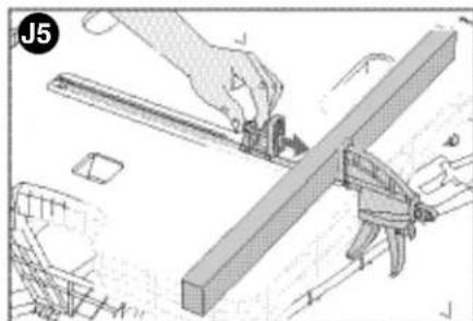
J5 - Depress the release lever and move the front jaw into position against the material to be clamped. Squeeze the front handle to apply pressure.
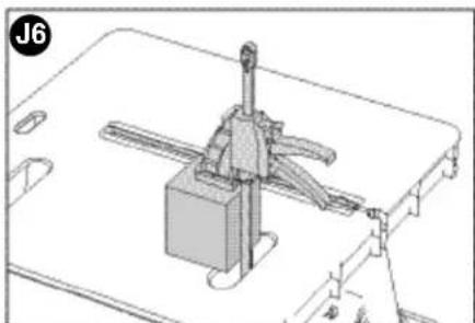
J6 - To clamp vertically, insert the clamp through the slot in the tabletop as shown.
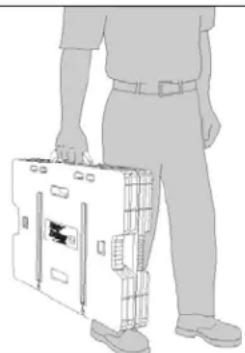
TRANSPORTING
- Carry the unit by the convenient carrying handle as shown in figure K.
Maintenance
Use only mild soap and damp cloth to clean the tool. Never let any liquid get inside the tool; never immerse any part of the tool into a liquid.
IMPORTANT: To assure product SAFETY and RELIABILITY, repairs, maintenance and adjustment should be performed by authorized service centers or other qualified service personnel, always using identical replacement parts.
Accessories
Recommended accessories for use with your tool are available from your local dealer or authorized service center. If you need assistance regarding accessories, please call: 1-800-544-6986.
WARNING: The use of any accessory not recommended for use with this tool could be hazardous.
Service Information
All Black & Decker Service Centers are staffed with trained personnel to provide customers with efficient and reliable power tool service. Whether you need technical advice, repair, or genuine factory replacement parts, contact the Black & Decker location nearest you. To find your local service location, refer to the yellow page directory under "Tools-Electric" or call: 1-800-544-6986 or visit www.blackanddecker.com
Full Two-Year Home Use Warranty
Black & Decker (U.S.) Inc., warrants this product for two years against any defects in material or workmanship. The defective product will be replaced or repaired at no charge in either of two ways.
The first, which will result in exchanges only, is to return the product to the retailer from whom it was purchased (provided that the store is a participating retailer). Returns should be made within the time period of the retailer's policy for exchanges (usually 30 to 90 days after the sale). Proof of purchase may be required. Please check with the retailer for their specific return policy regarding returns that are beyond the time set for exchanges.
The second option is to take or send the product (prepaid) to a Black & Decker owned or authorized Service Center for repair or replacement at our option. Proof of purchase may be required. Black & Decker owned and authorized Service Centers are listed under "Tools-Electric" in the yellow pages of the phone directory and on our website www.blackanddecker.com.
This warranty does not apply to accessories. This warranty gives you specific legal rights and you may have other rights which vary from state to state or province to province. Should you have any questions, contact the manager of your nearest Black & Decker Service Center. This product is not intended for commercial use.
FREE WARNING LABEL REPLACEMENT: If your warning labels become illegible or are missing, call 1-800-544-6986 for a free replacement.
Special Warranty Note to Contractors:
FIRESTORM™ branded products are offered as high end consumer home use tools and carry a HOME USE WARRANTY. These tools are designed, manufactured and tested to meet or exceed the needs of the do-it-yourselfer in the execution of projects and repairs in and around the home. With proper use they will provide the home owner with step up power and performance well beyond their two year warranty. However, if you use tools for a living and use FIRESTORM™ branded products or any of Black & Decker's other Consumer Home Use tools ON THE JOBSITE you should know that they CANNOT BE COVERED UNDER OUR WARRANTY.
Patents Pending
Imported by
Black & Decker (U.S.) Inc.,
701 E.Joppa Rd.
Towson, MD 21286 U.S.A.

BlackandDecker.com
1-800-544-6986
See 'Tools-Electric'
Yellow Pages - 1
for Service & Sales

K
Our tool are available from your local dealer or distance regarding accessories, please call:


FIRESTORM
HIGH PERFORMANCE TOOLS
OUTLIES A NAUT RENDAMENTEHNDEMISTRATES DE ALTO RENDIMENTIO

BLACK & DECKER
ETABILPOBIAJFF
AVEQ SERREJOINTS
GUIDE D'UTILISATION

Black & Decker Canada Inc.
100 Central Ave.
Col. Industrial Bravo
GUADALAJARA, JAL
Av. La Paz #1779
(33) 3825 6978
Col. Americana Sector Juarez
MEXICO.D.F.
Eie Central Lázaro Cardenas
No.18
(55) 5588 9377
Local D, Col. Obrera
MERIDA, YUC
Calle 63 #459-A
(999) 928 5038
Col. Centro
MONTERREY, N.L.
- BEFORE RETURNING THIS PRODUCT FOR ANY REASON PLEASE CALL 1-800-544-6986
- IMPORTANT SAFETY INSTRUCTIONS
- SAVE THESE INSTRUCTIONS FOR FUTURE USE
- OPERATION
- OPENING THE WORKBENCH
- CLOSING THE WORKBENCH
- ADJUSTABLE CLAMPS
- TRANSPORTING
- Maintenance
- Accessories
- Service Information
- Full Two-Year Home Use Warranty
- Special Warranty Note to Contractors:
- FIRESTORM
- HIGH PERFORMANCE TOOLS
- GUIDE D'UTILISATION
- GUADALAJARA, JAL
- MEXICO.D.F.
- MERIDA, YUC
- MONTERREY, N.L.
Brand : BLACK & DECKER
Model : FSWM1000
Category : Workbench