
AcousticPerformance AP5122m - Speaker QSC - Free user manual and instructions
Find the device manual for free AcousticPerformance AP5122m QSC in PDF.
User questions about AcousticPerformance AP5122m QSC
0 question about this device. Answer the ones you know or ask your own.
Ask a new question about this device
Download the instructions for your Speaker in PDF format for free! Find your manual AcousticPerformance AP5122m - QSC and take your electronic device back in hand. On this page are published all the documents necessary for the use of your device. AcousticPerformance AP5122m by QSC.
USER MANUAL AcousticPerformance AP5122m QSC
AcousticPerformance (AP)
User Guide
AP-5102 - 10" Two-way Trapezoidal Loudspeaker with 105° axisymmetric coverage
AP-5122 - 12" Two-way Trapezoidal Loudspeaker with 90^ axisymmetric coverage
AP-5152 - 15" Two-way Trapezoidal Loudspeaker with 75^ axisymmetric coverage
AP-5122m - 12" Two-way Multi-purpose Loudspeaker with 90^ axisymmetric coverage
EXPLANATION OF SYMBOLS
The term "WARNING!" indicates instructions regarding personal safety. If the instructions are not followed the result may be bodily injury or death.
The term "CAUTION!" indicates instructions regarding possible damage to physical equipment. If these instructions are not followed, it may result in damage to the equipment that may not be covered under the warranty.
The term "IMPORTANT!" indicates instructions or information that are vital to the successful completion of the procedure.
The term "NOTE" is used to indicate additional useful information.

The intent of the lightning flash with arrowhead symbol in a triangle is to alert the user to the presence of un-insulated "dangerous" voltage within the product's enclosure that may be of sufficient magnitude to constitute a risk of electric shock to humans.

The intent of the exclamation point within a triangle is to alert the user to the presence of important safety, and operating and maintenance instructions in this manual.

IMPORTANT SAFETY INSTRUCTIONS


WARNING!: While it is possible for one person to lift a loudspeaker, it is important to use proper lifting techniques. Suggested reading: OSHA Technical Manual on Back Disorders and Injuries (http://www.osha.gov/dts/osta/otm/otm_vii/otm_vii_1.html#app_vii:1_2).
- Keep these instructions.
- Heed all warnings.
- Follow all instructions.
- Do not use this apparatus near water.
- Clean only with a dry cloth.
- Adhere to all applicable, local codes.
- Do not install near any heat sources such as radiators, heat registers, stoves, or other apparatus (including amplifiers) that produce heat.
- Only use attachments/accessories specified by the manufacturer.
• Refer all servicing to qualified service personnel.
- Consult a licensed, professional engineer when any doubt or questions arise regarding a physical equipment installation.
TD-000369-00-B
*TD-000369-00*

Warranty (USA only; other countries, see your dealer or distributor)
QSC Audio Products 3 Year Limited Warranty
QSC Audio Products, LLC ("QSC") guarantees its products to be free from defective material and/or workmanship and will replace defective parts and repair malfunctioning products under this warranty when the defect occurs under normal installation and use, provided the unit is returned to our factory, one of our authorized service stations or an authorized QSC International Distributor via pre-paid transportation with a copy of proof of purchase (i.e., sales receipt). This warranty provides that the examination of the return product must indicate, in our judgment, a manufacturing defect. This warranty does not extend to any product which has been subjected to misuse, neglect, accident, improper installation, or where the date code has been removed or defaced. QSC shall not be liable for incidental and/or consequential damages. This warranty gives you specific legal rights. This limited warranty is freely transferable during the term of the warranty period. The warranty on QSC products is NOT VALID if the products have been purchased from an unauthorized dealer/online e-tailer, or if the original factory serial number has been removed, defaced, or replaced in any way. Damage to, or loss of any software or data residing on the product is not covered. When providing repair or replacement service, QSC will use reasonable efforts to reinstall the product's original software configuration and subsequent update releases, but will not provide any recovery or transfer of software or data contained on the serviced unit not originally included in the product.
Customers may have additional rights, which vary from state to state or from country to country. In the event that a provision of this limited warranty is void, prohibited or superseded by local laws, the remaining provisions shall remain in effect.
The QSC limited warranty is valid for a period of three (3) years from date of purchase in the United States and many (but not all) other countries.
For QSC warranty information in countries other than the United States, contact your authorized QSC international distributor. A list of QSC International distributors is available at www.qscaudio.com.
To register your QSC product online, go to www.qscaudio.com and select "Product Registration". Other questions regarding this warranty can be answered by calling, e-mailing or contacting your authorized QSC distributor.
Phone: 1-800-854-4079 within US and Canada, +1-714-754-6175 international, Email: warranty@qscaudio.com, Website: www.qscaudio.com.
Installing the AcousticPerformance Loudspeakers
Suspending the AP Loudspeakers

WARNING!: Read and follow these instructions carefully. If the loudspeakers are not suspended properly, they could fall, causing personal injury and damage to the equipment.
Rules for Suspension
- Consult a Professional Mechanical or Structural Engineer, licensed in the jurisdiction of the sound system installation, to review, verify, and approve all attachments to the building or structure.
- Employ the services of a Professional Rigger for hoisting, positioning, and attaching the equipment to the supporting structure.
- Correct use of all suspension hardware and components is imperative in sound system suspension and deployment.
• Always calculate suspended loads before lifting to make sure suspension components and hardware are used within their respective load limits. - Consult local codes and regulations to fully understand the requirements for suspended loads in the venue in which you will suspend the equipment.
- Use only the recommended yoke or the M10 installation points with the M10 installation kit for suspending the loudspeaker.
- Be absolutely certain of the integrity of any structural member intended to support suspended loads. Hidden structural members can have hidden structural weakness.
- Never assume anything! Owner or third-party supplied suspension attachment points may not be adequate for suspending the loads.
- Before lifting, always inspect all components (enclosures, suspension brackets, pins, frames, bolts, nuts, slings, shackles, etc.) for cracks, wear, deformation, corrosion, missing, loose, or damaged parts that could reduce the strength of the assembly. Discard any worn, defective, or suspect parts and replace them with new appropriately load-rated parts.
Shock Loading
When a load is either moved or stopped, its static weight is magnified. Sudden movements can magnify the static weight several times. This magnification of static weight is called "shock loading". Shock loading poses a danger to equipment and workers. The effects of shock loading can be instantaneous, or may remain undetected unless the equipment is visually damaged. Proper preparation for shock loading requires careful planning and knowledge of equipment, suspension, and lifting practices.
Shock loading of equipment and structures is usually confined to lifting and installation, but natural forces (winds, earthquakes, and so on) can impose shock loads several times the static load. Because of this, structures and suspension equipment must be capable of supporting several times the weight of the suspended equipment.
| Model Weight (kg) Weight (lbs) | ||
| AP-5102 21.8 | 48 | |
| AP-5122 29.7 | 66 | |
| AP-5152 36.3 | 80 | |
| AP-5122m 28 | 6 63 | |
Using Integrated Suspension Points
The Suspension points are located such that the loudspeakers can be hung in any orientation.
Models AP-5102 (10"), AP-5122 (12"), and AP-5152 (15")
• 15 M10 Integrated Suspension Points.
- Two on each side, three on the back, and four on the top, and four on the bottom of the loudspeaker enclosure.
Model AP-5122m
• 11 Integrated Suspension Points
- Three on each side, one on the back, two on the top, and two on the bottom.

NOTE: The suspension points on AcousticPerformance Loudspeakers are designed for use with the eyebolts (M10, 20 mm) and washers included in the available M10 accessory kit (model number: M10 KIT-W).
- Remove the appropriate plugs from the M10 installation points using a 6 mm hex key.
- Thread an eyebolt into each of the appropriate M10 installation points.
- Tighten the eyebolts until their shoulders are snug against the enclosure.
- Continue to rotate the eyebolts until they reach the optimum desired in-line position. Do not overtighten.
- The loudspeakers are ready for suspension.
Using Yoke Mounts
AcousticPerformance Loudspeakers can be installed using a yoke mount attached to the M10 Integrated Suspension Points. A 6 mm hex key is required.
• Model AP-5102 (10") uses the AP-YM10 Yoke Mount
• Model AP-5122 (12") uses the AP-YM12 Yoke Mount
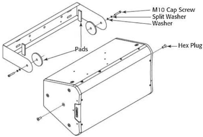
- Model AP-5122m (12" multi-purpose) uses the AP-YM12m Yoke Mount

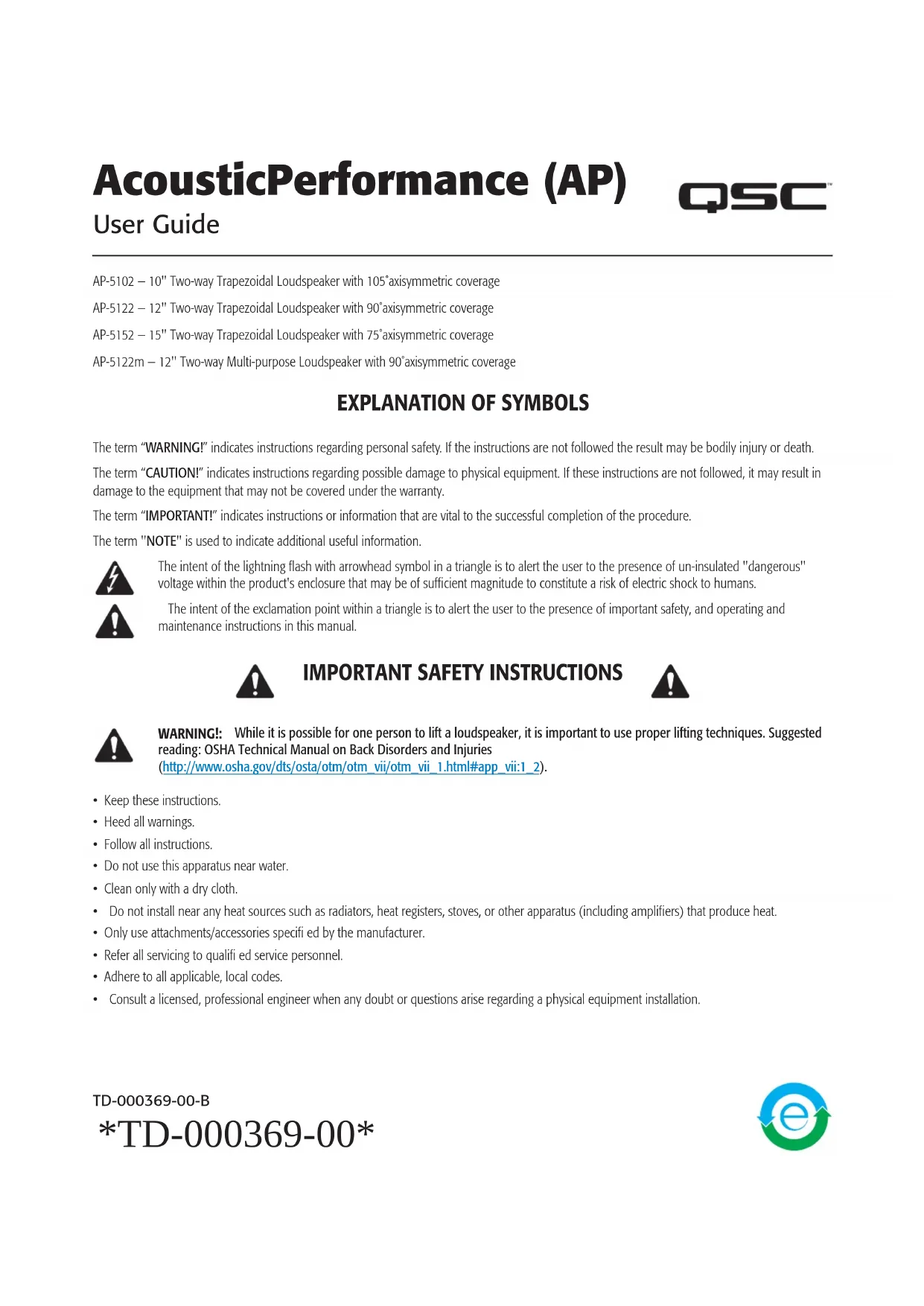
NOTE: The AP-5122m mounts perpendicular to the yoke. Refer to Figure 2.

WARNING!: Consult a structural engineer before mounting the Yoke Mounts to any surface. Be sure the surface can support the weight of the loudspeaker, and that the proper bolts are used to secure the yoke to the surface.
- Figure 1 -
ENG
- Properly secure the yoke mount bracket to the selected surface.
Refer to Figure 1 and Figure 2
- Remove the center M10 hex plugs from the top and bottom of the loudspeaker enclosure. You may discard or recycle the plugs.
- Using proper lifting techniques place the loudspeaker in the yoke with the two circular pads between the top and bottom of the loudspeaker enclosure and the yoke.
- Install the M10 socket head cap screw, lock washer, and fl at washer through the yoke and pad, and into the Integrated Suspension point. Repeat for the other end of the loudspeaker enclosure. Do not fully tighten the screws at this point.
- Adjust the angle of the loudspeaker as required.
- To prevent rattling with models AP-5102 and AP-5122 in a vertical orientation, install the two rectangular pads between the loudspeaker enclosure and the yoke mount.

NOTE: If you reposition the loudspeaker be sure to check that the rectangular pads are in the proper positions.
- Torque the M10 cap screws to 60 in/lbs.
- Figure 2 -
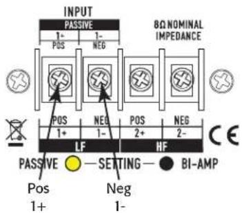
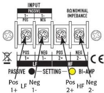
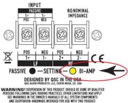
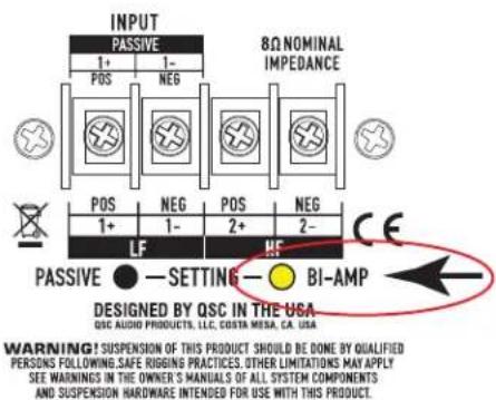
Connections
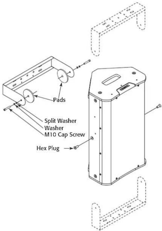
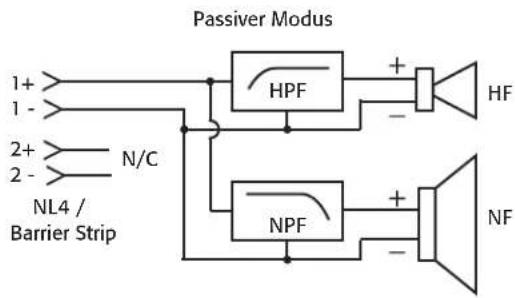
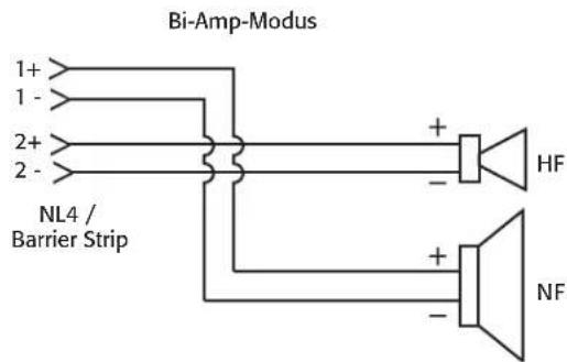
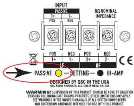
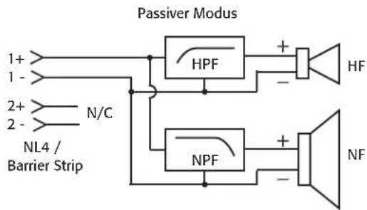
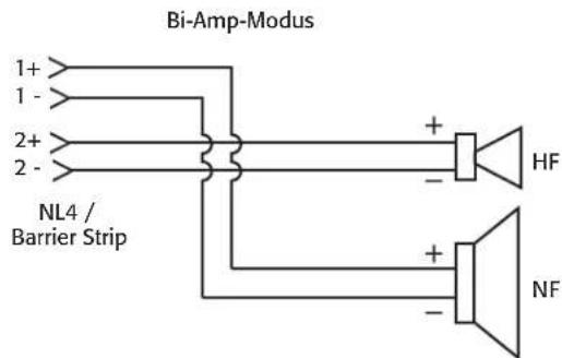
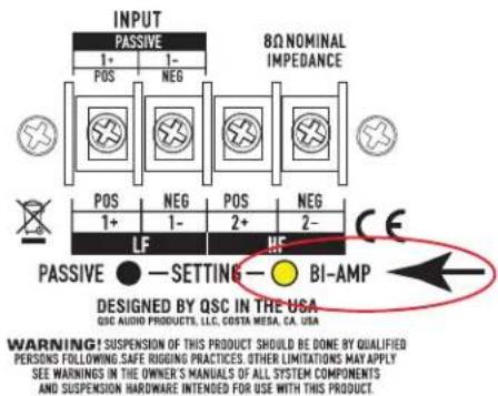
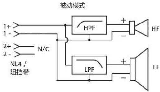
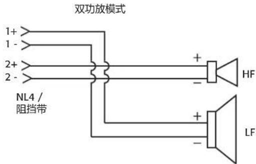
AcousticPerformance Loudspeaker are capable of switching between Passive and Bi-amp mode. Look at the Setting ports to determine the current mode. Yellow in the Setting port indicates the current mode. Refer to Figure 3 and Figure 4

NOTE: The default mode, from the factory, is the passive crossover network.
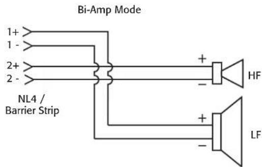
Passive mode Bi-Amp mode

- Figure 3 -

flowchart
graph TD
    A["1+"] --> B["HPF"]
    C["1-"] --> B
    D["2+"] --> E["N/C"]
    F["2-"] --> E
    G["NL4 / Barrier Strip"] --> B
    G --> H["LPF"]
    B --> I["HF"]
    E --> J["LF"]
    H --> K["-"]
    I --> L["+"]
    J --> M["-"]
- Figure 4 -
Changing from Passive to Bi-amp
All AcousticPerformance loudspeakers ship confi gured in passive mode. To change from Passive to Bi-amp mode or Bi-amp mode to Passive mode:
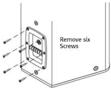
Refer to Figure 5 and Figure 6
- Remove the six screws holding the input cup in place.
- Remove the input cup, being careful not to place excess stress on the connecting wiring harness.
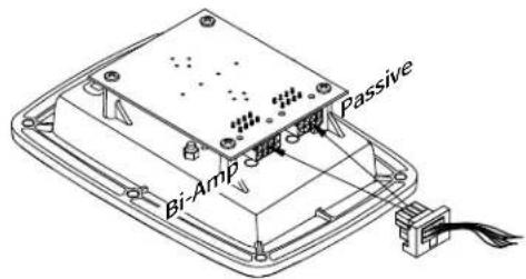
- Remove the wiring harness plug from the receptacle at the bottom of the cup.
- Insert the wiring harness plug into the other receptacle at the bottom of the cup.
- Turn the input cup over and verify that yellow is visible in the proper SETTING port. If not, move the plug to the other receptacle.
- Carefully place the input cup back into position on the enclosure, being careful not to bind or pinch any of the wires.
- Secure the input cup with the six screws removed in step 1. Do not overtighten.
- Figure 5 -
- Figure 6 -
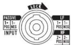
Wiring the AcousticPerformance Loudspeaker

WARNING!: Make sure the amplifiers are turned off, and disconnected from the power source, or the loudspeaker wiring is not connected to the amplifiers.
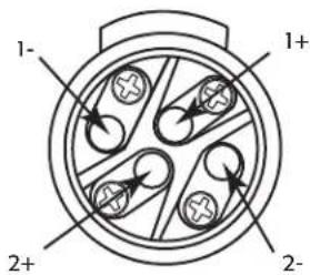
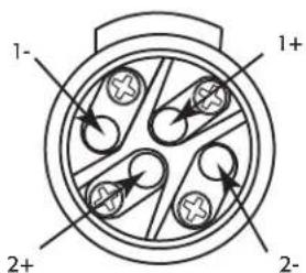
Refer to Figure 7, Figure 8, and Figure 9.
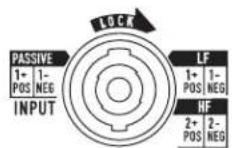
The pin numbers for the NL4 connector correspond to the pin numbers on the barrier strip.
Model AP-5122m utilizes NL4 connectors only.
Wiring
| Model Size Wiring Connections Wire Size Maximum | |||
| AP-5102 10" | Two-way NL4 and | covered 4-pin barrier strip | 10 AWG |
| AP-5122 12" | Two-way NL4 and | covered 4-pin barrier strip | |
| AP-5152 15" | Two-way NL4 and | covered 4-pin barrier strip | |
| AP-5122m 12" | Two-way Dual NL4 | ||
Refer to Figure 7 and Figure 9
-
Make sure the loudspeaker is set to the desired mode. Refer to "Changing from Passive to Bi-amp" on page 5.
-
Connect the wiring (10 AWG maximum) to the correct terminals if you are using the barrier strip.
Pin-out for the barrier strip and the NL4 connectors:
- Passive Mode:
- 1+ and 1-
- Bi-amp Mode:
。LF1+ and 1-
- HF 2+ and 2-

NOTE: The loudspeakers can be daisy-chained, in parallel, using one of the inputs as the output to the next loudspeaker.
Passive mode
Bi-Amp mode
-
Figure 8 -
-
Figure 7 -
- Figure 9 -
Specifications
| AP-5102 AP-5122 AP-5152 AP-5122m | ||||
| System Details | ||||
| Frequency Response (-10 dB): | 60 Hz -18 kHz | 48 Hz - 18 kHz 44 Hz - 18 kHz 55 Hz - 18 kHz | ||
| Power Capacity1 (Continuous) | ||||
| Passive | 54 V / 450 W | 60 V / 550 W | 65 V / 650 W | 60 V / 550 W |
| Bi-amp HF | 25 V / 80 W | 25 V / 80 W | 25 V / 80 W | 25 V / 80 W |
| Bi-amp LF | 54 V / 450 W | 60 V / 550 W | 65 V / 650 W | 60 V / 550 W |
| Nominal Sensitivity2 | 94 dB, 1 W @1 m | 95 dB, 1 W @1 m 96 dB, 1 W @1 m 95 dB, 1 W @1 m | ||
| Nominal Coverage Angle (Axisymmetric) | 105° | 90° 75° 90° | ||
| Directivity Factor (Q) | 4.6 | 6 8.3 6 | ||
| Directivity Index (DI) | 6.6 | 789.278 | ||
| Recommended Crossover | 950 Hz | 950 Hz 950 Hz 950 Hz | ||
| Maximum Rated SPL | ||||
| Passive: continuous3 | 121 dB @1 m | 122 dB @1 m | 123 dB @1 m | 122 dB @1 m |
| peak4 | 127 dB @1 m | 128 dB @1 m | 129 dB @1 m | 128 dB @1 m |
| Bi-Amp: HF continuous3 | 127 dB @1 m | 127 dB @1 m | 127 dB @1 m | 127 dB @1 m |
| LF continuous3 | 121 dB @1 m | 122 dB @1 m | 123 dB @1 m | 122 dB @1 m |
| HF peak4 | 133 dB @1 m | 133 dB @1 m | 133 dB @1 m | 133 dB @1 m |
| LF peak4 | 127 dB @1 m | 128 dB @1 m | 129 dB @1 m | 128 dB @1 m |
| Nominal Impedance | 8Ω | 8Ω 8Ω 8Ω | ||
| HF Transducer | 76 mm (3") diaphragm35.6 mm (1.4") exit ferrite compression driver; | 76 mm (3") diaphragm35.6 mm (1.4") exit ferrite compression driver; | 76 mm (3") diaphragm35.6 mm (1.4") exit ferrite compression driver; | 76 mm (3") diaphragm35.6 mm (1.4") exit ferrite compression driver; |
| LF Transducer | 76 mm (3 in) voice coil ferrite254 mm (10") woofer | 102 mm (4 in) voice coil ferrite305 mm (12") woofer | 102 mm (4 in) voice coil ferrite381 mm (15") woofer | 102 mm (4 in) voice coil ferrite305 mm (12") woofer |
| Enclosure Details | ||||
| Input Connector | Covered Barrier StripNL4 | Covered Barrier StripNL4 | Covered Barrier StripNL4 | Dual NL4 |
| Pin Out | 1+/1- Passive / Bi-amp LF2+/2- Bi-amp HF | 1+/1- Passive / Bi-amp LF2+/2- Bi-amp HF | 1+/1- Passive / Bi-amp LF2+/2- Bi-amp HF | 1+/1- Passive / Bi-amp LF2+/2- Bi-amp HF |
| Enclosure Material | 15 mm Baltic birch plywood 15 mm Baltic birch plywood 15 mm Baltic birch plywood 15 mm Baltic birch plywood | |||
| Attachment Points | 15x threaded M10 inserts | 15x threaded M10 inserts | 15x threaded M10 inserts | 11x threaded M10 inserts |
| Color | Black (RAL 9011)White (RAL 9010) | Black (RAL 9011)White (RAL 9010) | Black (RAL 9011)White (RAL 9010) | Black (RAL 9011) |
| Grille | 16 Gauge powder coated steel | 16 Gauge powder coated steel | 16 Gauge powder coated steel | 16 Gauge powder coated steel |
| Dimensions (H x W x D) | 559 x 305 x 267 mm(22 x 12 x 10.5 in) | 660 x 381 x 330 mm(26 x 15 x 13 in) | 813 x 445 x 386 mm(32 x 17.5 x 15.2 in) | 660 x 381 x 286 mm(26 x 15 x 11.3 in) |
| Net Weight | 21.8 kg (48 lbs) | 29.5 kg (65 lbs) | 36.3 kg (80 lbs) | 28.6 kg (63 lbs) |
| Shipping Weight | 24 kg (53 lbs) | 33 kg (72 lbs) | 41 kg (90 lbs) | 32 kg (71 lbs) |
| Optional Accessories | AP-YM10 Yoke MountM10 Kit-W | AP-YM12 Yoke MountM10 Kit-W | M10 Kit-W | AP-YM12m Yoke MountM10 Kit-W |
1 2 hour rating using IEC60268 noise based on minimum impedance
2 Mid-band based on nominal impedance
3 Calculated as the nominal sensitivity plus 10x the log of continuous rated power in volts squared, divided by nominal impedance
4 Calculated as the continuous calculated max output plus 6 dB
QSC™
Mailing Address:
QSC Audio Products, LLC
1675 MacArthur Boulevard
Costa Mesa, CA 92626-1468 USA
Telephone Numbers:
Main Number: (714) 754-6175
Sales & Marketing: (714) 957-7100 or toll free (USA only) (800) 854-4079
Customer Service: (714) 957-7150 or toll free (USA only) (800) 772-2834
Facsimile Numbers:
Sales & Marketing FAX: (714) 754-6174
Customer Service FAX: (714) 754-6173
World Wide Web:
www.qscaudio.com
E-mail:
info@qscaudio.com
service@qscaudio.com
AcousticPerformance (AP)
Guía del usuario

- Figura 3 -
flowchart
graph TD
    A["1+"] --> B["HPF"]
    C["1-"] --> B
    D["2+"] --> E["N/P"]
    F["2-"] --> E
    G["NL4 / Barrier Strip"] --> H["NPF"]
    B --> I["+"]
    E --> J["-"]
    H --> K["+"]
    L["HF"] --> M["Output"]
    N["NF"] --> O["Output"]
- Figura 4 -
Cambio del modo Pasivo al modo Bi-Amp
- Figura 6 -
- Figura 8 -
- Figura 9 -
Especifi caciones
| AP-5102 AP-5122 AP-5152 AP-5122m | ||||
| Detalles del sistema | ||||
| Respuesta de frecuencias (-10 dB): | 60 Hz - 18 kHz | 48 Hz - 18 kHz 44 Hz - 18 kHz 55 Hz - 18 kHz | ||
| Capacidad de potencia1 (continua) | ||||
| Pasivo | 54 V / 450 W | 60 V / 550 W | 65 V / 650 W | 60 V / 550 W |
| Bi-Amp HF | 25 V / 80 W | 25 V / 80 W | 25 V / 80 W | 25 V / 80 W |
| Bi-Amp LF | 54 V / 450 W | 60 V / 550 W | 65 V / 650 W | 60 V / 550 W |
| Sensibilidad nominal2 | 94 dB, 1 W a 1 m | 95 dB, 1 W a 1 m 96 dB, 1 W a 1 m 95 dB, 1 W a 1 m | ||
| Ángulo de cobertura nominal(axximétrica) | 105° | 90° 75° 90° | ||
| Factor de directividad (Q) | 4,6 | 6 8,3 6 | ||
| Índice de directividad (DI) | 6,6 | 7,8 9,2 7,8 | ||
| Cruce recomendado | 950 Hz | 950 Hz 950 Hz 950 Hz | ||
| SPL nominal máximo | ||||
| Pasivo:continuo3pico4 | 121 dB a 1 m127 dB a 1 m | 122 dB a 1 m128 dB a 1 m | 123 dB a 1 m129 dB a 1 m | 122 dB a 1 m128 dB a 1 m |
| Bi-Amp:HF continuo3LF continuo3HF pico4LF pico4 | 127 dB a 1 m121 dB a 1 m133 dB a 1 m127 dB a 1 m | 127 dB a 1 m122 dB a 1 m133 dB a 1 m128 dB a 1 m | 127 dB a 1 m123 dB a 1 m133 dB a 1 m129 dB a 1 m | 127 dB a 1 m122 dB a 1 m133 dB a 1 m128 dB a 1 m |
| Impedancia nominal | 8 Ω | 8 Ω 8 Ω 8 Ω | ||
| Transductor HF | diafragma de 76 mm (3")excitador de compresión desalida de ferrita de 35,6 mm(1,4"); | diafragma de 76 mm (3")excitador de compresión desalida de ferrita de 35,6 mm(1,4"); | diafragma de 76 mm (3")excitador de compresión desalida de ferrita de 35,6 mm(1,4"); | diafragma de 76 mm (3")excitador de compresión desalida de ferrita DE 35,6 mm(1,4"); |
| Transductor LF | ferrita de bobina de vozde 76 mm (3")woofer de 254 mm (10") | ferrita de bobina de vozde 102 mm (4")woofer de 305 mm (12") | ferrita de bobina de vozde 102 mm (4")woofer de 381 mm (15") | ferrita de bobina de vozde 102 mm (4")woofer de 305 mm (12") |
| Detalles de la caja | ||||
| Conector de entrada | Tira de barrera cubiertaNL4 | Tira de barrera cubiertaNL4 | Tira de barrera cubiertaNL4 | NL4 Doble |
| Salida de patillas | 1+/1- Pasivo / Bi-Amp LF2+/2- Bi-Amp HF | 1+/1- Pasivo / Bi-Amp LF2+/2- Bi-Amp HF | 1+/1- Pasivo / Bi-Amp LF2+/2- Bi-Amp HF | 1+/1- Pasivo / Bi-Amp LF2+/2- Bi-Amp HF |
| Material de la caja | contrachapado de abedul bálticode 15 mm | contrachapado de abedul bálticode 15 mm | contrachapado de abedul bálticode 15 mm | contrachapado de abedul bálticode 15 mm |
| Puntos de sujeción | 15x insertos roscados M10 15x insertos roscados M10 15x insertos roscados M10 11x insertos roscados M10 | |||
| Color | Negro (RAL 9011)Blanco (RAL 9010) | Negro (RAL 9011)Blanco (RAL 9010) | Negro (RAL 9011)Blanco (RAL 9010) | Negro (RAL 9011) |
| Parrilla | Acero de calibre 16 recubierto de polvo | Acero de calibre 16 recubierto de polvo | Acero de calibre 16 recubierto de polvo | Acero de calibre 16 recubierto de polvo |
| Dimensiones (Al x An x Pr) | 559 x 305 x 267 mm(22 x 12 x 10,5 pulg.) | 660 x 381 x 330 mm(26 x 15 x 13 pulg.) | 813 x 445 x 386 mm(32 x 17,5 x 15,2 pulg.) | 660 x 381 x 286 mm(26 x 15 x 11,3 pulg.) |
| Peso neto | 21,8 kg (48 lb) | 29,5 kg (65 lb) 36,3 kg (80 lb) 28,6 kg (63 lb) | ||
| Peso de envío | 24 kg (53 lb) | 33 kg (72 lb) | 41 kg (90 lb) | 32 kg (71 lb) |
| Accesorios opcionales | Montaje de horquilla AP-YM10Juego M10-W | Montaje de horquilla AP-YM12Juego M10-W | Juego M10-W | Montaje de horquilla AP-YM12mJuego M10-W |
QSC Audio Products, LLC
1675 MacArthur Boulevard
service@qscaudio.com
AcousticPerformance (AP)
Mode Passive Mode Bi-Amp
- Illustration 3 -
FRE
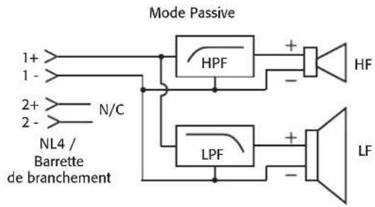
flowchart
graph TD
    A["1+"] --> B["HPF"]
    C["1-"] --> B
    D["2+"] --> E["N/C"]
    F["2-"] --> E
    G["NL4 / Barrette de branchement"] --> H["LPF"]
    H --> I["HF"]
    H --> J["LF"]
    B --> K["+"]
    E --> L["-"]
    I --> M["+"]
    J --> N["-"]
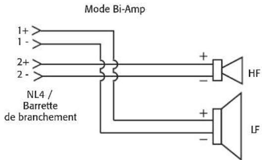
- Illustration 4 -
- Illustration 6 -
- Illustration 9 -
QSC Audio Products, LLC
1675 MacArthur Boulevard
service@qscaudio.com
AcousticPerformance (AP)
Bedienungsanleitung
- Abbildung 3 -
GER
flowchart
graph TD
    A["1+"] --> B["HPF"]
    C["1-"] --> B
    D["2+"] --> E["N/C"]
    F["2-"] --> E
    G["NL4 / Barrier Strip"] --> H["NPF"]
    B --> I["+"]
    E --> J["-"]
    H --> K["+"]
    L["HF"] --> M["Output"]
    N["NF"] --> O["Output"]
- Abbildung 4 -
- Abbildung 6 -
- Abbildung 9 -
Technische Daten
QSC Audio Products, LLC
1675 MacArthur Boulevard
Costa Mesa, CA 92626-1468 USA
Telefonnummern:
service@qscaudio.com
AcousticPerformance (AP)
用户指南
AP-5102 — 10" 双向梯形扬声器,轴对称覆盖角度为 105^
AP-5122 — 12" 双向梯形扬声器,轴对称覆盖角度为 90^
AP-5152 — 15" 双向梯形扬声器,轴对称覆盖角度为 75^
— 图 3 —
flowchart
graph TD
    A["1+"] --> B["HPF"]
    C["1-"] --> B
    D["2+"] --> E["N/C"]
    F["2-"] --> E
    G["NL4 / 阻挡带"] --> H["HPF"]
    I["HF"] --> J["+"]
    K["LF"] --> L["+"]
    B --> M["-"]
    E --> N["-"]
    H --> O["-"]
    L --> P["-"]
— 图 9 —
规格
QSC Audio Products, LLC
1675 MacArthur Boulevard
Costa Mesa, CA 92626-1468 USA
电话:
总机:(714) 754-6175
service@qscaudio.com