B160100DPSI - Receiver Tripp Lite - Free user manual and instructions
Find the device manual for free B160100DPSI Tripp Lite in PDF.

| Product Type | IP Audio/Video Receiver |
| Brand | Tripp Lite |
| Model | B160-100-DPSI |
| Power Supply | External power supply (included) |
| Maximum Video Resolution | 1920 x 1080 (1080p) |
| Maximum Distance (point-to-point) | 100 m (328 ft) with Cat5e/6 cable |
| Maximum Distance (via switch) | 200 m (656 ft) total |
| Input Connector | 1 x RJ45 (IP) |
| Output Connector | 1 x DisplayPort |
| Additional Connectors | 1 x RS-232 (DB9 or 3.5 mm), 1 x IR-IN (3.5 mm), 1 x IR-OUT (3.5 mm) |
| Video Compression | H.264 |
| IR Control | Frequency 20-60 kHz |
| RS-232 | Baud rate up to 57,600 bps |
| HDCP Compatibility | Yes |
| Mounting | Wall, rack (19 in), or pole mount (hardware included) |
| Warranty | 1 year |
| Dimensions (approx.) | 10 x 8 x 2 cm |
| Weight (approx.) | 200 g |
| Included Accessories | Power supply, IR-IN/IR-OUT cables, 3.5 mm to DB9 adapter, mounting hardware, manual |
| Care and Cleaning | Clean with a dry, non-abrasive cloth. Do not use liquids. |
| Safety | Do not expose to moisture or extreme temperatures. Use with a surge protector. |
| Spare Parts and Repairability | Repairs must be carried out by an authorized center. Contact Tripp Lite for parts. |
Frequently Asked Questions - B160100DPSI Tripp Lite
User questions about B160100DPSI Tripp Lite
0 question about this device. Answer the ones you know or ask your own.
Ask a new question about this device
Download the instructions for your Receiver in PDF format for free! Find your manual B160100DPSI - Tripp Lite and take your electronic device back in hand. On this page are published all the documents necessary for the use of your device. B160100DPSI by Tripp Lite.
USER MANUAL B160100DPSI Tripp Lite
Audio/Video with RS-232 and IR Control over IP Extenders
Extender Kit Models:
B160-101-DPSI
B160-101-DPHDSI
B160-101-HDSI
B160-103-HDSI
B160-201-HSI
B160-202-HDSI
B160-301-HDSI
Transmitter Models:
B160-001-CSI
B160-001-DPSI
B160-001-HDSI
B160-001-VSI
Receiver Models:
B160-100-CSI
B160-100-DPSI
B160-100-HDSI
B160-100-VSI
B160-200-HSI
Espanol 25 • Français 50 • Pycckn 75
WARRANTY REGISTRATION
Register your product today and be automatically entered to win an ISOBAR surge protector in our monthly drawing!
www.triplite.com/warranty


Manufacturing Excellence.
1111 W. 35th Street, Chicago, IL 60609 USA • www.triplite.com/support
Copyright © 2019 Tripp Lite. All trademarks are the sole property of their respective owners.
Package Contents
| B160-001-CSI | B160-001-DPSI | B160-001-HDSI | B160-001-VSI | B160-100-CSI | B160-100-DPSI | B160-100-HDSI | B160-100-VSI | B160-200-HSI | B160-101-DPSI | B160-101-DPHDI | B160-101-HDSI | B160-103-HDSI | B160-202-HSI | B160-202-HDSI | B160-203-HDSI | B160-204-HDSI | B160-205-HDSI | |
| Transmitter (T), Receiver (R), Kit (K) | TTTT | RRRR | RRRR | KKKK | KKKK | KKKK | KKKK | KKKK | KKKK | KKKK | KKKK | KKKK | KKKK | KKKK | KKKK | KKKK | KKKK | |
| External Power Supply 1 | 11 | 11 | 11 | 11 | 22 | 22 | 42 | 44 | ||||||||||
| IR-In Cable 000011 | 11 | 11 | 11 | 11 | 23 | |||||||||||||
| IR-Out Cable 11100 | 000 | 11 | 11 | 13 | 12 | 1 | ||||||||||||
| 3.5 mm to DB9 M/Adapters Cable | 110 | 10 | 00 | 00 | 11 | 10 | 80 | 21 | ||||||||||
| 3.5 mm to DB9 M/Adapters Cable | 000 | 01 | 10 | 11 | 11 | 10 | 11 | 23 | ||||||||||
| HDMI to DVIAdapters Cable | 001 | 00 | 01 | 00 | 01 | 2 | 40 | 44 | ||||||||||
| Mounting Hardware YYY | YYYY | YYYY | YYYY | YYYY | YYYY | YY | ||||||||||||
| Owner's Manual YYYYY | YYYYYY | YYYYYY | YYYYYY | YYYYYY | YY |
Optional Accessories
A008-006 Component Video Gold Cable - 6 ft.
N202-Series Cat6, 24 AWG, Solid-Wire Patch Cables
NSS-G16D2 16-Port Gigabit L2 Managed Switch with 8-Outlet PDU
NSS-G24D2 24-Port Gigabit L2 Managed Switch with 12-Outlet PDU
P502-Series VGA Cables with RGB Coax
P520-006 RS-232 Serial Extension Cable - 6 ft.
P561-Series DVI-D Single-Link Cables
P566-Series HDMI to DVI Adapter Cables
P568-Series High-Speed HDMI Cables
- P569-XXX-LOCK* High-Speed HDMI Cables with Ethernet and Locking Connectors
P580-Series DisplayPort™ Cables
P583-Series Mini DisplayPort to DisplayPort Cables
*XXX refers to the length, with cables available in 6 ft. (006), 10 ft. (010) and 15 ft. (015) lengths.
Product Features
- Extends and distributes audio/video, serial and IR control signals over Cat5/Cat6 cabling.
- Models available with Component Video + Stereo Audio, DisplayPort, HDMI**, and VGA + Stereo Audio.
- Converts source video to an IP-based signal that can be transmitted to and distributed through a network switch.
- Transmitters can be located up to 328 ft. (100 m) from the switch, with an additional 328 ft. (100 m) between the switch and the receiver, for a total distance of 656 ft. (200 m).
- Can also be used in a point-to-point installation where the transmitter directly connects to a receiver up to 328 ft. (100 m) away.
- Designed for managed network switches with IGMP, which allow login and remote management via the switch interface.
- Video source can be sent to any analog or digital display (e.g. Component Video to HDMI, VGA to HDMI, HDMI to DisplayPort, HDMI to HDMI).
- Display a single source on a single monitor or distribute a single signal to multiple monitors.
- B160-200-HSI and B160-201-HSI receiver units include two HDMI output ports for connection of two monitors.
- Connect up to 64 transmitters and 255 receivers in a single managed switch installation.
- Utilizes H.264 video compression standard.
- Extends IR control signals that control a source (such as a Blu-ray™ player) from a remote display.
Uses a 20kHz to 60kHz IR frequency.
Supports RS-232 Serial baud rates up to 57600 bps. - VGA video models support video resolutions up to 1920 x 1440, including 1080p.
- DisplayPort and HDMI models support video resolutions up to 1920 x 1080 (1080p).
Product Features
- Component video models support video resolutions up to 1080i.
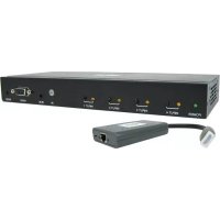
Each transmitter features an HDMI output port for connecting a local monitor. - HDCP and 3D compatible.
- Includes mounting hardware for wall-mount, rack mount or pole mount installations.
- Plug and play; no software or drivers required.
**Connect a DVI source and/or monitor using an HDMI to DVI adapter (select models include an HDMI to DVI adapter). HDMI to DVI adapter cables (Tripp Lite P566-Series) are available, sold separately.
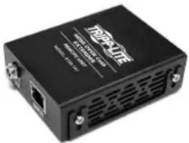
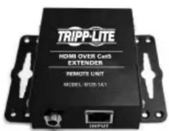
Mounting Instructions
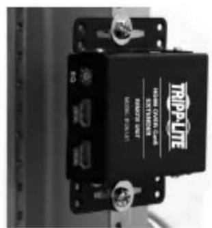
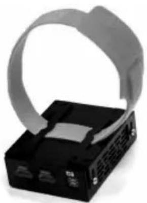
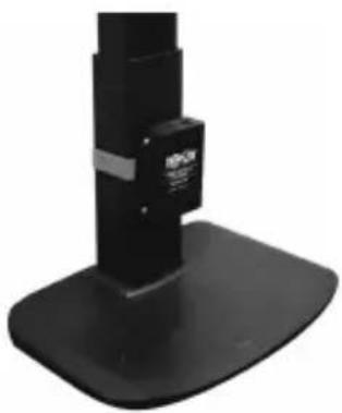
Audio/Video over IP extenders include mounting hardware that allows for a variety of mounting options. The following images demonstrate these mounting methods.
Note: Model B126-1A1 is shown for illustrative purposes; installation for Audio/Video over IP extender units is the same.

Wall-mount
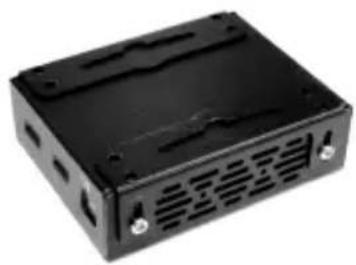

19" Rack-mount

Pole-mount
Point-to-Point Installation
Notes:
- Test to ensure the entire installation works properly before pulling cables through ceilings/walls.
- To achieve maximum distance and performance, use 24 AWG solid wire Cat5e/6 cable. Using stranded wire cable or cable with a gauge (AWG) size higher than recommended will result in a shorter extension distance. Higher gauge cabling (such as 26 AWG) has a limited transmission capability compared to lower-gauge cabling. All Tripp Lite N202-Series Cat6 cables use 24 AWG solid wire cabling. Extended lengths of 23 AWG solid wire Cat6a cable are available from Tripp Lite as a custom order.
-
Transmitter and receiver kits are available in DisplayPort, HDMI and VGA, but separate transmitters and receivers can be purchased in any combination (e.g. Component Video to HDMI, VGA to HDMI, HDMI to VGA, HDMI to DisplayPort).
-
Ensure all equipment to be connected is powered off.
- Connect the audio/video source to the transmitter unit's input port (see Optional Accessories for available Tripp Lite audio/video cables).
- (Optional) Connect the computer's DB9 port to the transmitter unit's serial port. Depending on the model, the serial port will be either DB9 or 3.5mm . Models with 3.5mm jacks include a 3.5mm to DB9 adapter. Models with DB9 ports require standard RS-232 DB9 cable (sold separately) for connecting to a computer.
- (Optional) Connect the included IR-OUT cable to the transmitter unit's IR-OUT port. Place the sensor on the IR-OUT cable in an unobstructed area within clear view of the device being controlled.
Note: The IR-OUT cable receives the signal from the remote control and sends it to the device being controlled (e.g. Blu-ray player, etc.).
- (Optional) Using an HDMI cable, connect a local monitor to the transmitter unit's HDMI output port (see Optional Accessories for available Tripp Lite HDMI cables).
- Connect the external power supply to the local transmitter unit and plug it into a Tripp Lite Surge Protector, Uninterruptible Power Supply (UPS) or Power Distribution Unit (PDU).
Point-to-Point Installation
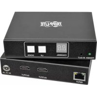
- Press the Up / Down buttons to set the Channel Number (0-63) on the front of the transmitter unit to a number that will also be used on the receiver unit.
Note: A locking mechanism prevents the Channel Number from being unintentionally changed. When the Channel Number is locked, hold down the Up and Down buttons until the Channel Number starts blinking. Then navigate to the desired Channel using the Up / Down buttons. Once the desired Channel Number has been selected, lock the Channel Number by holding down the Up and Down buttons until the Channel Number stops blinking.
- Using Cat5e/6 cable, connect the transmitter unit's RJ45 Output port to the receiver unit's RJ45 Input port.
Note: The maximum allowable cable length from transmitter to receiver is 328 ft. (100 m).
-
Connect a monitor to the receiver unit's audio/video Output port (See Optional Accessories for available Tripp Lite audio/video cables).
-
(Optional) Connect the serial device's DB9 port to the receiver unit's serial port. Depending on the model, the serial port will be either DB9 or 3.5mm . Models with 3.5mm jacks include a 3.5mm to DB9 adapter. Models with DB9 ports require standard RS-232 DB9 cable (sold separately) for connecting a device.
-
(Optional) Connect the included IR-IN cable to the receiver unit's IR-IN port. Place the sensor on the IR-IN cable in an unobstructed area within clear view of the device being controlled.
Note: The IR-IN cable accepts a signal from a remote control and sends it to a device being controlled on the other end of the installation.
- Connect the external power supply to the receiver unit and plug it into a Tripp Lite Surge Protector, Uninterruptible Power Supply (UPS) or Power Distribution Unit (PDU).
Point-to-Point Installation
- Press the Up / Down buttons to set the Channel Number (0-63) on the front of the receiver unit to a number also used on the transmitter unit.
Note: A locking mechanism prevents the Channel Number from being unintentionally changed. When the Channel Number is locked, hold down the Up and Down buttons until the Channel Number starts blinking. Then navigate to the desired Channel using the Up / Down buttons. Once the desired Channel Number has been selected, lock the Channel Number by holding down the Up and Down buttons until the Channel Number stops blinking.
- Power on all connected devices.
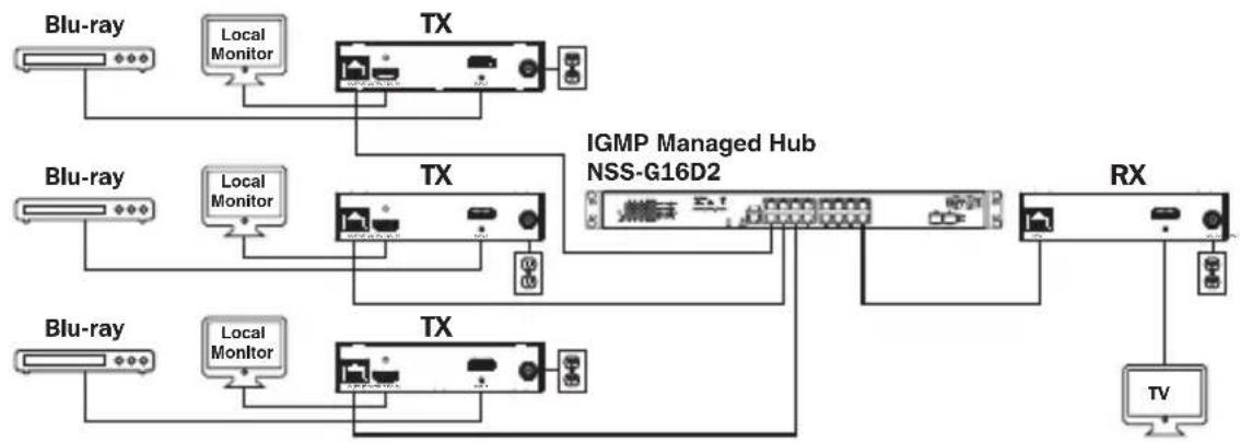
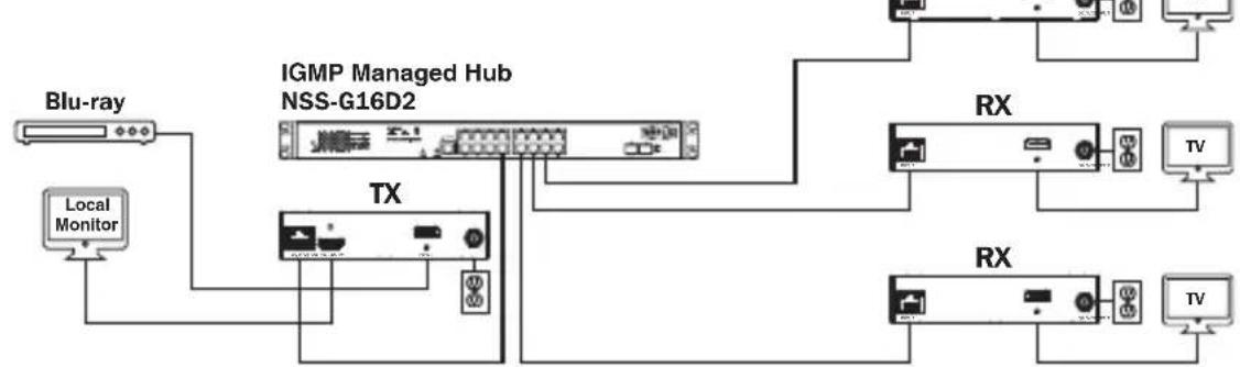
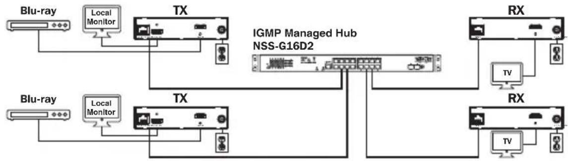
Point-to-Multipoint Installation - Managed Switch with IGMP
Notes:
- Test to ensure the entire installation works properly before pulling cables through ceilings/walls.
- To achieve maximum distance and performance, use 24 AWG solid wire Cat5e/6 cable. Using stranded wire cable or cable with a gauge (AWG) size higher than recommended will result in a shorter extension distance. Higher gauge cabling (such as 26 AWG) has a limited transmission capability compared to lower-gauge cabling. All Tripp Lite N202-Series Cat6 cables use 24 AWG solid wire cabling. Extended lengths of 23 AWG solid wire Cat6a cable are available from Tripp Lite as a custom order.
- B160-Series Audio/Video over IP Extenders are designed for use with a dedicated network switch. Connecting IP Extenders to a switch used with other networking equipment will result in degraded or non-functional product performance.
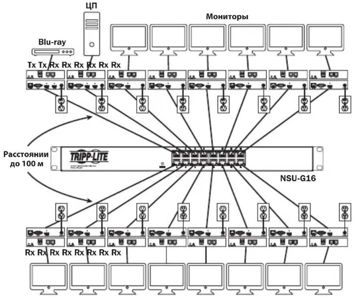
- The installation diagram on the next page shows HDMI transmitters and receivers only, though any combination of transmitters and receivers (e.g. Component Video, DisplayPort, HDMI, VGA) may be used. Up to 64 transmitters and 255 receivers can be connected in a single managed switch installation (the diagram shown stops at a single 16-port network switch).
- The installation diagram on the next page shows only required connections. Optional connections (such as the IR-IN and IR-OUT Cables) are not shown.
Point-to-Multipoint Installation - Managed Switch with IGMP
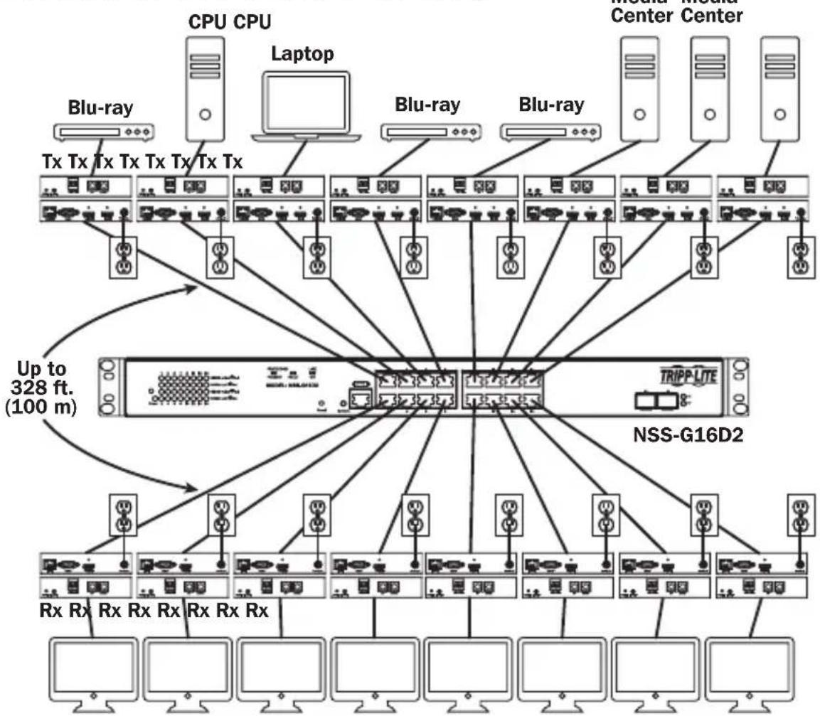
Installation Overview (All Models)
Point-to-Multipoint Installation - Managed Switch with IGMP
B160-103-HDSI Kit
B160-301-HDSI Kit
B160-202-HDSI Kit
Point-to-Multipoint Installation - Managed Switch with IGMP
- Ensure all equipment to be connected is powered off.
- Connect the audio/video source to the transmitter unit's input port (see Optional Accessories for available Tripp Lite audio/video cables).
- (Optional) Connect the computer's DB9 port to the transmitter unit's serial port. Depending on the model, the serial port will be either DB9 or 3.5mm . Models with 3.5mm jacks include a 3.5mm to DB9 adapter. Models with DB9 ports require standard RS-232 DB9 cable (sold separately) for connecting to a computer.
- (Optional) Connect the included IR-OUT cable to the transmitter unit's IR-OUT port. Place the sensor and cable in an unobstructed area within clear view of the device being controlled.
Note: The IR-OUT cable receives the signal from the remote control and sends it to the device being controlled (e.g. Blu-ray player, etc.).
- (Optional) Using an HDMI cable, connect a local monitor to the transmitter unit's HDMI output port (see Optional Accessories for available Tripp Lite HDMI cables).
- Set the Channel Number (0 to 63 are available) on the front of the transmitter to a desired number by pressing the Up / Down buttons. This number MUST be the same on all transmitter and receiver units in the installation. If you are using transmitter and receiver units that are all brand new, they will default to Channel Number 0 and you can leave the channel unchanged upon installation.
Note: A locking mechanism prevents the Channel Number from being unintentionally changed. When the Channel Number is locked, hold down the Up and Down buttons until the Channel Number starts blinking. Then navigate to the desired Channel using the Up / Down buttons. Once the desired Channel Number has been selected, lock the Channel Number by holding down the Up and Down buttons until the Channel Number stops blinking.
- Connect the RJ45 Output port on the transmitter unit to an RJ45 port on the network switch using Cat5e/6 cable.
Note: The maximum allowable cable length from transmitter to switch is 328 ft. (100 m).
Point-to-Multipoint Installation - Managed Switch with IGMP
Do not connect the external power supply to the transmitter at this time. The transmitter should not be powered on until all audio/video equipment is connected and powered on.
- To connect additional transmitter(s), repeat steps 2 through 7.
- Connect a monitor to the receiver unit's audio/video Output port (See Optional Accessories for available Tripp Lite audio/video cables).
- (Optional) Connect the serial device's DB9 port to the receiver unit's serial port. Depending on the model, the serial port will be either DB9 or 3.5mm . Models with 3.5mm jacks include a 3.5mm to DB9 adapter. Models with DB9 ports require standard RS-232 DB9 cable (sold separately) for connecting a device.
- (Optional) Connect the included IR-IN cable to the receiver unit's IR-IN port. Place the sensor on the IR-IN cable in an unobstructed area within clear view of the remote control.
Note: The IR-IN cable accepts a signal from a remote control and sends it to a device being controlled on the other end of the installation.
- Set the Channel Number (0 to 63 are available) on the front of the receiver to a desired number by pressing the Up / Down buttons. This number MUST be the same on all transmitter and receiver units in the installation. If you are using transmitter and receiver units that are all brand new, they will default to channel number 0, and you can leave the channel unchanged upon installation.
Note: A locking mechanism prevents the Channel Number from being unintentionally changed. When the Channel Number is locked, hold down the Up and Down buttons until the Channel Number starts blinking. Then navigate to the desired Channel using the Up / Down buttons. Once the desired Channel Number has been selected, lock the Channel Number by holding down the Up and Down buttons until the Channel Number stops blinking.
- Connect the RJ45 Input port on the receiver unit to an RJ45 port on the network switch using Cat5e/6 cable.
Note: The maximum allowable cable length from receiver to switch is 328 ft. (100 m).
Point-to-Multipoint Installation - Managed Switch with IGMP
Do not connect the external power supply to the receiver at this time. The receiver should not be powered on until all audio/video equipment is connected and powered on.
- To connect additional receivers, repeat steps 9 through 13.
- Power on all connected devices.
- Connect the external power supplies to all transmitter and receiver units in the installation, then plug the external power supplies into Tripp Lite Surge Protectors, Uninterruptible Power Supplies (UPS) or Power Distribution Units (PDU).
Operation of Point-to-Multipoint Installation - Managed Switch with IGMP
Notes:
- B160-Series Audio/Video over IP Extenders are designed for use with a dedicated network switch. Connecting IP Extenders to a switch used with other networking equipment will result in degraded or non-functional product performance.
-
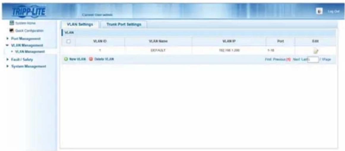
The model screenshots shown in the steps below are a Tripp Lite NSS-G16D2 Network Switch. Operation of different switches will vary by model.
-
Log into the network switch user interface.
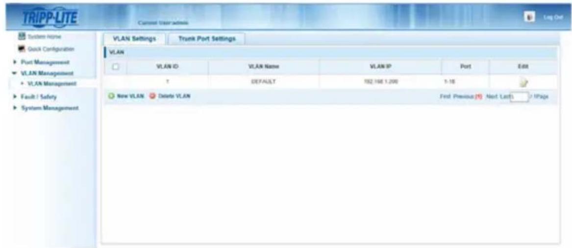
- Navigate to the VLAN Management section.
Operation of Point-to-Multipoint Installation - Managed Switch with IGMP
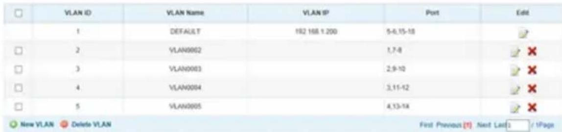
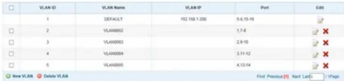
- In the VLAN Management section, create a new VLAN for each transmitter in the installation. The transmitter port number should always be the first number in the VLAN, followed by the port numbers (separated by commas) of all receiver units that will be transmitting audio/video to and from the selected transmitter. The screenshot below shows VLAN's for four transmitters (VLAN0002 through VLAN0005). VLAN0002 represents the transmitter connected to port 1, the audio/video of which is transmitted to the receivers connected to ports 7 and 8. Similarly, VLAN0003 represents the transmitter connected to port 2, whose audio/video is transmitted to receivers connected to ports 9 and 10.
-
To switch the source of the audio/video on a receiver, go to and edit the VLAN of the associated transmitters to add/remove the desired ports.
-
As more transmitters and receivers get added to the installation, simply add additional VLANs for the new transmitters and add the new receivers to the VLANs of the desired transmitters.
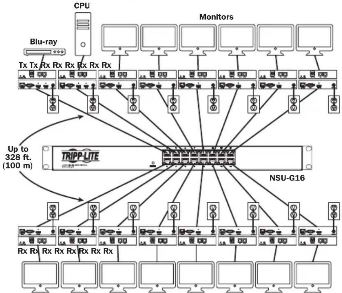
Point-to-Multipoint Installation - Unmanaged Switch
Notes:
- Unmanaged switch installations are limited to two transmitter units. The number of receiver units is limited to the number of ports remaining on the unmanaged switch.
- Test to ensure the entire installation works properly before pulling cables through ceilings/walls.
- To achieve maximum distance and performance, use 24 AWG solid-wire Cat5e/6 cable. Using stranded-wire cable or cable with a gauge (AWG) size higher than recommended will result in a shorter extension distance. Higher-gauge cabling (such as 26 AWG) has a limited transmission capability compared to lower-gauge cabling. All Tripp Lite N202-Series Cat6 cables use 24 AWG solid-wire cabling. Extended lengths of 23 AWG solid-wire Cat6a cable are available from Tripp Lite as a custom order.
- B160-Series Audio/Video over IP Extenders are designed for use with a dedicated network switch. Connecting IP Extenders to a switch used with other networking equipment will result in degraded or non-functional product performance.
- The installation diagram on the next page shows HDMI transmitters and receivers only, though any combination of transmitters and receivers (e.g. Component Video, DisplayPort, HDMI, VGA) may be used.
- The installation diagram on the next page shows only required connections. Optional connections (such as the IR-IN and IR-OUT Cables) are not shown.
Point-to-Multipoint Installation – Unmanaged Switch
Installation Overview (All Models)
- Ensure all equipment to be connected is powered off.
- Connect the audio/video source to the transmitter unit's input port (see Optional Accessories for available Tripp Lite audio/video cables).
- (Optional) Connect the computer's DB9 port to the transmitter unit's serial port. Depending on the model, the serial port will be either DB9 or 3.5mm . Models with 3.5mm jacks include a 3.5mm to DB9 adapter. Models with DB9 ports require standard RS-232 DB9 cable (sold separately) for connecting to a computer.
Point-to-Multipoint Installation - Unmanaged Switch
- (Optional) Connect the included IR-OUT cable to the transmitter unit's IR-OUT port. Place the sensor on the IR-OUT cable in an unobstructed area within clear view of the device being controlled.
Note: The IR-OUT cable receives the signal from the remote control and sends it to the device being controlled (e.g. Blu-ray player, etc.).
- (Optional) Using an HDMI cable, connect a local monitor to the transmitter unit's HDMI output port (see Optional Accessories for available Tripp Lite HDMI cables).
- Set the Channel Number (0 to 63 are available) on the front of the transmitter to a desired number by pressing the Up / Down buttons. The channel number of all transmitters in the installation MUST be different.
Note: A locking mechanism prevents the Channel Number from being unintentionally changed. When the Channel Number is locked, hold down the Up and Down buttons until the Channel Number starts blinking. Then navigate to the desired Channel using the Up / Down buttons. Once the desired Channel Number has been selected, lock the Channel Number by holding down the Up and Down buttons until the Channel Number stops blinking.
- Connect the RJ45 Output port on the transmitter unit to an RJ45 port on the network switch using Cat5e/6 cable.
Note: The maximum allowable cable length from receiver to switch is 328 ft. (100 m).

Do not connect the external power supply to the transmitter at this time. The transmitter should not be powered on until all audio/video equipment is connected and powered on.
- To connect an additional transmitter, repeat steps 2 through 7.
- Connect a monitor to the receiver unit's audio/video Output port (See Optional Accessories for available Tripp Lite audio/video cables).
- (Optional) Connect the serial device's DB9 port to the receiver unit's serial port. Depending on the model, the serial port will be either DB9 or 3.5mm . Models with 3.5mm jacks include a 3.5mm to DB9 adapter. Models with DB9 ports require standard RS-232 DB9 cable (sold separately) for connecting a device.
Point-to-Multipoint Installation - Unmanaged Switch
- (Optional) Connect the included IR-IN cable to the receiver unit's IR-IN port. Place the sensor on the IR-IN cable in an unobstructed area within clear view of the remote control.
Note: The IR-IN cable accepts a signal from a remote control and sends it to a device being controlled on the other end of the installation.
- Set the Channel Number (0 to 63 are available) on the front of the receiver to match the channel number of the transmitter whose audio/video you want to receive by pressing the Up / Down buttons.
Note: A locking mechanism prevents the Channel Number from being unintentionally changed. When the Channel Number is locked, hold down the Up and Down buttons until the Channel Number starts blinking. Then navigate to the desired Channel using the Up / Down buttons. Once the desired Channel Number has been selected, lock the Channel Number by holding down the Up and Down buttons until the Channel Number stops blinking.
- Connect the RJ45 Input port on the receiver unit to an RJ45 port on the network switch using Cat5e/6 cable.
Note: The maximum allowable cable length from receiver to switch is 328 ft. (100 m).

Do not connect the external power supply to the receiver at this time. The receiver should not be powered on until all audio/video equipment is connected and powered on.
- To connect additional receivers, repeat steps 9 through 13.
- Power on all connected devices.
- Connect the external power supplies to all transmitter and receiver units in the installation, then plug the external power supplies into Tripp Lite Surge Protectors, Uninterruptible Power Supplies (UPS) or Power Distribution Units (PDU).
- Once in operation, change the monitor source signal by simply changing the channel of the corresponding receiver to match that of the transmitter with the desired source signal.
Troubleshooting
If unable to receive an acceptable image after following the installation instructions, try the following troubleshooting tips:
- Are the included external power supplies connected and plugged into a working power source? For the product to function properly, it must be connected to and receiving power from the external power supply.
- Was the power to the connected devices turned off prior to installation? If not, restart all connected devices.
- Were the connected audio/video devices powered on before the transmitter and receiver units? If not, disconnect power from all transmitter and receiver units, then power them back on.
- What resolution are you trying to obtain? Make sure the installation is within the maximum distance and resolution specs supported by the model as referenced in the Product Features section of this manual. If unable to obtain an acceptable image, try lowering the computer's video resolution or adjusting the refresh rate.
- What type of cabling is used in the installation? Inferior cabling can result in poor performance. It is important to use cables that support the desired video resolution. To achieve maximum distance and resolution, 24 AWG solid-wire Cat5e/6 cable or 23 AWG solid-wire Cat6a cable must be used. Tripp Lite's N202-Series Cat6 cables use 24 AWG solid wire, as do the N022-01K-GY (Cat5) and N222-01K-GY bulk cables. The audio/video cables used must also support the desired video resolution. Inexpensive, low quality cables may not support the maximum resolution. It is recommended that you use the Tripp Lite cables listed in the Optional Accessories section of this manual.
- Test the cables to ensure they are working properly. For example, connect the audio/video cable between a source and functioning monitor to ensure the cable is not defective. For Cat5e/6 cable, connect it between a computer and a network to verify it establishes a network connection.
Troubleshooting
- Check cabling for any damages that may have occurred during installation. If a cable connector is loosened from pulling through ceilings/wall or the cable jacket is damaged with the wiring exposed, maximum performance will not be achieved.
- Are the transmitter(s) and/or receiver(s) located in an area with exposure to higher temperatures? If the product is overheated, it will not function properly.
- Do not set identical channel numbers for transmitters in an Unmanaged Switch installation. Doing so will result in no signal being displayed on monitors connected to receivers assigned to the same channel number. If this happens, change the transmitters' channel numbers to unique numbers and assign the desired channel number to the affected receivers. If audio/video does not reappear after doing this, disconnect power from the affected transmitter and receiver units, wait 10 seconds, and reconnect the power.
- Do not connect more than two transmitters in an unmanaged switch installation. Unmanaged switch installations are limited to two transmitters, with the number of receivers being limited to the number of ports remaining on the unmanaged switch.
- Do not connect other networking equipment to the network switch. The B160-Series Audio/Video over IP Extenders are designed for use with a dedicated network switch. Connecting them to a switch used with other networking equipment will result in degraded or non-functional product performance.
Warranty and Product Registration
1-Year Warranty
Tripp Lite warrants its products to be free from defects in materials and workmanship for a period of one (1) year from the date of initial purchase. Tripp Lite's obligation under this warranty is limited to repairing or replacing (at its sole option) any such defective products. To obtain service under this warranty, you must obtain a Returned Material Authorization (RMA) number from Tripp Lite or an authorized Tripp Lite service center. Products must be returned to Tripp Lite or an authorized Tripp Lite service center with transportation charges prepaid and must be accompanied by a brief description of the problem encountered and proof of date and place of purchase. This warranty does not apply to equipment, which has been damaged by accident, negligence or misapplication or has been altered or modified in any way.
EXCEPT AS PROVIDED HEREIN, Tripp Lite MAKES NO WARRANTYES, EXPRESS OR IMPLIED, INCLUDING WARRANTYES OF MERCHANTABILITY AND FITNESS FOR A PARTICULAR PURPOSE. Some states do not permit limitation or exclusion of implied warranties; therefore, the aforesaid limitation(s) or exclusion(s) may not apply to the purchaser.
EXCEPT AS PROVIDED ABOVE, IN NO EVENT WILL Tripp Lite BE LIABLE FOR DIRECT, INDIRECT, SPECIAL, INCIDENTAL OR CONSEQUENTIAL DAMAGES ARISING OUT OF THE USE OF THIS PRODUCT, EVEN IF ADVISED OF THE POSSIBILITY OF SUCH DAMAGE. Specifically, Tripp Lite is not liable for any costs, such as lost profits or revenue, loss of equipment, loss of use of equipment, loss of software, loss of data, costs of substitutes, claims by third parties, or otherwise.
PRODUCT REGISTRATION
Visit www.triplite.com/warranty today to register your new Tripp Lite product. You'll be automatically entered into a drawing for a chance to win a FREE Tripp Lite product!*
- No purchase necessary. Void where prohibited. Some restrictions apply. See website for details.
FCC Notice, Class B
This device complies with part 15 of the FCC Rules. Operation is subject to the following two conditions: (1) This device may not cause harmful interference, and (2) this device must accept any interference received, including interference that may cause undesired operation.
Note: This equipment has been tested and found to comply with the limits for a Class B digital device, pursuant to part 15 of the FCC Rules. These limits are designed to provide reasonable protection against harmful interference in a residential installation. This equipment generates, uses and can radiate radio frequency energy and, if not installed and used in accordance with the instructions, may cause harmful interference to radio communications. However, there is no guarantee that interference will not occur in a particular installation. If this equipment does cause harmful interference to radio or television reception, which can be determined by turning the equipment off and on, the user is encouraged to try to correct the interference by one or more of the following measures:
- Reorient or relocate the receiving antenna.
- Increase the separation between the equipment and receiver.
- Connect the equipment into an outlet on a circuit different from that to which the receiver is connected.
- Consult the dealer or an experienced radio/TV technician for help.
Any changes or modifications to this equipment not expressly approved by Tripp Lite could void the user's authority to operate this equipment.
Tripp Lite has a policy of continuous improvement. Specifications are subject to change without notice. Photos and illustrations may differ slightly from actual products.


1111 W. 35th Street, Chicago, IL 60609 USA • www.triplite.com/support
Copyright © 2019 Tripp Lite.
Note: El cable IR-IN accepts a new signal to the control remoto and the envia a new dispositivo that can be used for the installation of the installation.
Note: El cable IR-IN accepts a new signal to the control remoto and the envia a new dispositivo that can be used to monitor the installation.
1111 W. 35th Street, Chicago, IL 60609 USA • www.triplite.com/support
1111 W. 35th Street, Chicago, IL 60609 USA • www.triplite.com/support
PykoBODCTBO N0Ib30BaTeJia
PetpancIaTOpbl aydno-/BndeocnHaIa c pa3bemom RS-232 n IK-ynpaBleHneM no npotoKoIy IP
Modell petpansTopoB B
KOMnneKeTe:
B160-101-DPSI
B160-101-DPHDSI
B160-101-HDSI
B160-103-HDSI
B160-201-HSI
B160-202-HDSI
B160-301-HDSI
Moden
NepedaTcuKOB:
B160-001-CSI B160-001-DPSI
B160-001-HDSI B160-001-VSI
Moden
PnEmHKnOB:
B160-100-CSI B160-100-DPSI
B160-100-HDSI
B160-100-VSI B160-200-HSI
English 1 • Espanol 25 • Français 50

TRIPP·LITE

PpOPOPMN MIOHIOO HONNOHO
1111 W. 35th Street, Chicago, IL 60609 USA • www.triplite.com/support
OxpaHareTcraBTopCKnM npaBOM © 2019 Tripp Lite.
Bce ToproBbIe 3HaKn ABnOToC nckHIOHTeBHO CO6CTBEHHOCbONX COOTBeTcBYIOUX BlaJeBueB.
CopexHmoe ynaKOBKn
| PtepeDarutyuk (T), Ptpemekhuk (R), Kowmnek (R) | |||||||||
| Bheelunni Gnok NITATNAH | |||||||||
| Bxodhoi MK-ka6genb | |||||||||
| Bxodhoi MK-ka6genb | |||||||||
| Bxodhoi MK-ka6genb | |||||||||
| Bxodhoi MK-ka6genb | |||||||||
| Bxodhoi MK-ka6genb | 1111111112224244 | B160-001-CSI | |||||||
| 1111111112224244 | B160-001-DPSI | ||||||||
| 11111111123 | B160-001-HDSI | ||||||||
| 11111111123 | B160-001-VSI | ||||||||
| 11111111123 | B160-100-CSI | ||||||||
| 11111111123 | B160-100-DPSI | ||||||||
| 11111111123 | B160-100-HDSI | ||||||||
| 11111111123 | B160-100-VSI | ||||||||
| 11111111123 | B160-200-HSI | ||||||||
| 11111111123 | B160-101-DPSI | ||||||||
| 11111111123 | B160-101-DPHDSI | ||||||||
| 11111111123 | B160-101-HDSI | ||||||||
| 11111111123 | B160-103-HDSI | ||||||||
| 11111111123 | B160-201-HSI | ||||||||
| 11111111123 | B160-202-HDSI | ||||||||
| 11111111123 | B160-301-HDSI | ||||||||
| Pykovobodstvo nonbisobatren | |||||||||
| Mothrakchke bne pncitnco6henk | |||||||||
| Ma6genb-nepeoxoHnikc | |||||||||
| Ka6genb-nepeoxoHnikc | |||||||||
| Ka6genb-nepeoxoHnikc | |||||||||
| Ka6genb-nepeoxoHnikc | |||||||||
| Ka6genb-nepeoxoHnikc | |||||||||
| Ka6genb-nepeoxo Hnikc | |||||||||
| Ka6genb-nepeoxo Hnikc | |||||||||
| Ka6genb-nepeoxo Hnikc | |||||||||
| Ka6genb-nepeoxo Hnikc | |||||||||
| Ka6genb-nepeoxo Hnikc | |||||||||
OnuohalbHbIe KOMnKeKtYuOuNe
CoeHHTbHbI Ka6eB NpepaN KOMNoHrTO BuaOcHHa c No30NoeHHbIMN BbIBoMaM A008-006, dHa 1,8 M
- CoeHnTeBhIe Ka6eN Cat6 cepu N202 cOJHOKInbHbIM npoBoaMn KaIb6pa 24 AWG
- 16-nopToBbIynpaBnEmbIcTeBoiKoMMyTaTOpGigabitL2MoJ.NSS-G16D2c8-p03eToHbIM PDU
- 24-nopTobIy ynpabnembI ceTeBOI KOMMyTaTop Gigabit L2 MoI. NSS-G24D2 c 12-po3eToHbIM PDU
VGA-ka6eenn cepnn P502 c koakcnabhbimpa3beMaMn RGB
- ydnnHntbHbI Ka6eB P520-006 cnoceIOBaTeNbHbIMn pa3beMaMn RS-232, dHa 1,8 M
- OdnokhaHalbhe KabeN DVI-D cepn P561
Ka6eHn-epexoHnKc cepnn P566 c pa3bemamn HDMi n DVI
- BbICOKoCKOpocThbIe HDMI-Ka6eJIncepn P568
- BbICOKoCKOpocThbIe HDMI-ka6eIIN P569-XXX-LOCK* cpa3beMaMn Ethernet n FmKcnpuoummn BnHTaMn
Ka6eNn DisplayPortTM cepnn P580
- Ka6eIi cepnn P583 c pa3bemamn Mini DisplayPort n DisplayPort
*XXX COOTBETCTBYET DnHHe. BbInyckaemblie Ka6eHN HMeHOT DnHHy 1,8 M (006), 3 M (010) u 4,5 M (015).
XapakTepeNCTnKn npOdyKta
- 06ecneuBaetpeTpaHcIaIIO npacnpedeJIeHne ayduo-/BnDEOCnHaJOB, a TaKKe CnHaJOB nCTaHIOHHoro ynpabIeHnC nocJeIOBaTeIbHO nOdkJIIOyAembIX n HΦpaKpaChbIX yCTpoiCTB uepe3 ka6eni Cat5/Cat6.
- Bыньсаимье модени ИмEOSТ pa3bembl Component Video + Stereo Audio, DisplayPort, HDMI** n VGA + Stereo Audio.
- П_REобра3ует Видевocинан, постунош OT Источниа, В сигдан, КOTорь может поедаВа tcя на ceTeвой kommyTaTOp и распегдяТся чeрз Hero сИСпОлььЗованем поТOKола IP.
- IpepaTnki Moryt paonolaraTbca Ha pacctoHnn Do 100 M ot KOMMyTaTopa, pacctoHne MeKdy KOMMyTaTopom N npneMHNKOM TaXke MoXe TcoCTabIaTb Do 100 M, YTO oBeceuHbaet cyMMapHoe pacctoHne Do 200 M.
Moryt taKke nCnoB3oBaTbCByCTaHOBkax C DByxToeHuonToNoIorne, rKe nepeDaTuNK noKnIOuaeTcHnOcePdCTBeHHo K npHeMHNky Ha pacctOAHmdo 100 m. - Ппенизачесны дя упаьяемьix ceTeБых KOMMyTaTOpOB, pa6ToaHux no npotoKony IGMP,уTo 06ecneuBAeT BO3MOxHOCtB BXOДa B CnCTeMy I nIcTaHmOHHOу упаьеня чepe3 Иntepфс KOMMyTaTOPa.
- Bindeocurhan ot nctouhka moKeT hAnpaBnTbCra Ha IIO6o aHaIorOBbI uN cHpOBoD nucnnei (Hanpimep, uee3 ka6eJb c pa3bemamn Component Video-HDMI, VGA-HDMI, HDMI-DisplayPort, HDMI-HDMI).
- 06ecneuBaIOT OTo6paJekHe NcHnla OT OndHOrO nCTouHnka Ha OndHom MOHTope nn paCnpedeJeHne OndHOro CnHaJa MeKdY HeCKoJIbKIMM MOHToPamN.
- Пиемные мodyн B160-200-HSI и B160-201-HSI подва вьхоньх пораз HDMI на подкlioоченя К дByM MOHITOPaM.
- 06ecneuBAOT noKIOUeHne do 64 nepeaTukOB u 255 npneMHNKOB ByCTaHOBKe cOHNm ynpabJIeMbIM KOMMyTaTOPoM.
- IcnoIb3yeTcTaHdApT CkaTnB uIeocuHaHa H.264.
- PeTpacnlaunIK-cnHAnOB ynpaBHeHnIcToHnKOM (HaNPmep npourpbBaTeen Blu-rayTM) ot DnCTaHnOHHOro DnCnneJ.
- IcnoIb3yEmbI cneKtp IK-vaCToT: 20-60 KΓι.
- Пондержka ckоростеи пераши данньх уерз полесоватьн вптерфс RS-232 до 57600 6nt/c.
- MoDéni c pa3bēmamn VGA noDæpXnBaIbT BnDεopa3peHnna do 1920 x 1440, BkIouaay 1080p.
XapakTepeNCTnKn npOdyKta
- MoDéNi cpa3bēmAmi DisplayPort n HDMI noДeρЖиBaIr BnDEopa3peSeHnЯdo 1920 x 1080 (1080p).
- MoDéni cpa3bemamn Component Video noDpeXnBaHTo BnuDeopa3peWeHnI do 1080i.
KazdIy pepeaTcHmEeT BbXoHNo nopT HDMI Ira noKnUohnna JokAbHo ro MoHToPa.
CobMeCTHMOCTb C CNTeMaMn HDCP n 3D.
B KOMPJIeK T BKNIOUeHa MOHTaXHnOCHAcTka IJN KPeIJIeHn K CTHe, B CToIKe IIN Ha MaUte. - Повлочене поTekhalorn Plug-and-play 6e3 Heo6xOIMocTи nCnoIb3OBAHЯ KaKOro-ln60 nporpaMMHoro o6ecneueHЯ uN dpaBepOB.
**06ecneuBAOT noKIOUeHHe nCTOHHka DVI-cnHaIa n/nn MoHtopa c nCnoB3oBaHneM nepexoHnka HDMI-DVI (NeKOToPbIe moJIeN KOIIeKTKyIcTpeXoHnKOM HDMI-DVI). BInyckaemble KOMnaHnei Tripp Lite Ka6ennepexoHnKn HDMI-DVI (cepN P566) npodaIcT oTdeNbHO.
Hnctpykunno moHTaJx
IP-peTpaHcIaTopb ayDno-/BnDeocnHaNoB KOMPNeKTyOTc MoHTaxHoJ OChAcTKo, o6ecneuBaHOe B03MOxHOCt b KpeJIeHn pa3NHybIM cNoCobAm. 3Tu cNoCobbl KpeJIeHn Ioka3aHbI Ha npEcdTabHeHHbx HIXe UllIOCTpaunx.
PpmeHne. Ha nIIOCTpaunx noka3aHa moenb B126-1A1; yctaHOBka IP-peTpaHCnTOpOB ayno-/BundeocnHaNo OB cyueCTBnEeTc aHaONuHbIM cno6oM.
HaTeHHbIM MoHTax


MoHTaX B 19-ДIOIMOBOД CTоИke
YCTaHOBka C DByXToUeHOn TOnOJOrNeI
Примочаня:
- Ipeep npotraBaanem Ka6enee chepe3 ctehbl/ntoTkn Heo6xOJMo npOBepuB npaBnIbHOCTb yHKUHNOPOBaHn BcE uCTaHOBKn.
-ДяdoctnueHmaKcimambHoi nIcTahuHm n npOn3BODnteHbOCTn nCnoNb3yIte Ka6enb Cat5e/6 c OHOxINbHbIMn npOBaMn KaIn6pa 0,2 MM². NcNoJIb3oBaHne Ka6eЯ C MHOroXINbHbIMn npOBaMn IIN KabeЯ c npOBaMn KaIn6pa Bblse MM² npBedeT K cokpaeeHIO dINHbpeTpacnau. Ka6eI 6Oonee BbICOKIX KaIn6pOB (HaPImep, 0,13 MM²) IMeOT orpaHnueHHy IO nepeAioUyIO cNoCo6HoCTb NO cpaBHeHIO C Ka6eMaM 6Oone Hn3Knx KaIn6pbOB. BCE Ka6eN Cat6 cepNI N202 MapKn Tripp Lite n3rOtabNaIOcTc NcNoJIb3oBaHMe mOHOxINbHbIX npOBaOB KaIn6pa 0,2 MM². IIO INDINbUdYaIBHOmy 3aKa3a KOMnaHry Tripp Lite moKeT n3rOtabNbBaTb Ka6eN Cat6a yBeInuEHHoI dINHbI c NcNoJIb3oBaHneM oHOxINbHbIX npOBaOB KaIn6pa 0,26 MM². - Параатчки и ппсemнки, постаягьемы в komплжтса с разьемMU DisplayPort, HDMI u VGA, HO otдевно peam3уемы параатчки и ппсemнки могут IMeMb pa3bembl B lo6bix coetahnx (hanpimep, Component Video-HDMI, VGA-HDMI, HDMI-DisplayPort, HDMI-HDMI).
1.перд наалом установки Bce полк nullець оборудане дожнхо 6ытб obecтоцho.
2. IodKJIIOUHTe NCTOCHNK ayDnO-/BnDEOCnIHana K BXoHOMy nopTy nepeJaIOJero MoIyJIa (BbIpyckaemblcMoJeN ayno-/BnDEOKa6eJei Tripp Lite nepeuNCJIeHb B pa3dene OnCuHOHaBhIe KomnKeTlyoume).
- (Heo6aTeBHO) CoeHHTe npT DB9 KOMbItepa c nocneIOBaTeBbHbIM npToM nepeaOJero MoUyJI. B 3abucmOCTn OT moJIe NocNEIOBaTeBbHbI npOT MOKeT IMeT b HTEpEic DB9 nn 3,5 MM. MoJIe C pa3bEmAmN 3,5 MM KOMJIeKTyOTcR nepExOHNKOM 3,5 MM — DB9. Ira noDKIouEnn K KOMbItepy MoJIeN C npTAMN DB9 Tpe6yeTcR cTaHApTHbI Ka6eNb c pa3bEmAmN RS-232 n DB9 (npOdaetc oTdeBHo).
- (Heo6a3aTeNbHO) BCTaBbTe BbIXOHOH IK-Ka6eNB (IR-OUT) n3 KOMnIeKTA B npot IR-OUT nepeaIOUeRO moyna. UcTahOBITE DaTuNK Ha Ka6eNB IR-OUT B CBO6OHOH OT npenrTCTBm MeCe TaKIM 06pa3OM, YTO6bl ynpabJIeMoe yCTpoiCTBO HaxOJIOcB B npedeJAX npraMoB BuDMOCTN. PpimueHne. Ka6eNB IR-OUT npHHMaet cHnAn DnCTAHuONHOrO ynpabJIeHn I nepeaET erO ha ynpabJIeMoe yCTpoiCTBO (HaNPmep, npouRpbIbATENB Blu-ray n np.).
- (Heo6aTeBho) IoknHHTe loKaHbM MoHtOp K BbIXOHOmy npTy HDMI nepeaioero moyra c noMoUbHDMI-ka6enr (BbInyckaemble moJeHDMI-ka6ene Tripp Lite nepeuCnebl B pa3dene OOnnoHaHbHbe KOMnKeKtyouane).
- Поdkлочи Всшнь снок петаши К мecтому поюшу мodyю в BKлочи eroВ po3eTKy ceteBOrO ФпьТра, 6noka paCnpdeelenha петаши (PDU) nnn nctouHnka 6ecnepe60horo
YCTaHOBka C DByXToUeHOn TOnOJOrNei
nntanra (NbPi) Tripp Lite.
- Спомоью конок Up/Down (В蜱с/Bин3) на подемаюся мodyлу установке Homep kaHana (0-63), cootbeTCTbUOuTomy, kOtOpbI 6yIeT nCNoIb3OBaTbcR B npHemHom Modyne.
PpmeaHne. J3aunbIOTcnyauHoro n3MeHeHnHomepa KaHana npedyCMOTpeH mexaHn3M fKcauH. Pn 3aФHKCupOBaHHOM Homepe KaHana yepxmbTe KhoNkUp (Bbepx) uDown (BHN3) hxaTbIMn Do Tex nop, noka Hmep KaHana He NaHT MraTb. 3aTe mpeiDnte Ha Jeaembl KaHan c NMOUbO KhoNOK Up/Down (Bbepx/Bn3). Iocne Bby6opa Jenaemoro Homepa KaHana 3aФHKCupyTe erO, ydepXnbA KhoNkUp (Bbepx) u Down (Bn3) do tex nop, noka Homep KaHana He npekpaNT MraTb.
- CoeHHnTe BbIXoHoi nopT RJ45 (Output) nepeaioero moyna CBXoHbIM npToM RJ45 npHeMHoro moyra (Input) npn nomou n Ka6ena Cat5e/6.
PnmuueaHne. MaKcunMaJIbHO DoNyCTmMa JInHa Ka6eIa, CoedinHryoJero nepeDaTuNK C npneMHIKOM, coCTabJIeT 100 M.
-
Поdkлочte монитор к aydno-/Bundeobbixody (Output) npneMHoro Modyna (BbInyckaemble Modenaydno-/Bundeoka6ene Tripp Lite cm.В pa3dene OnucnoHaNbHbIe KOMPNeKtTuOuIe).
-
(Heo6aTeNbHo) CoeHnHTe nopT DB9 nocJeIOBATEbHO noKlOyAmOуCTpoIcTba c nocJeIOBATEbHbIM npToM npEHHOrO moUyJI. B 3aBucmOcTn OT moJIeN IOcJeIOBATEbHbIM npT moKeT mEt b uHTepfeyC DB9 nn 3,5 MM. MoJIeN C pa3bemamn 3,5 MM KOMJIeKtYOTc nepeXoHNkOM 3,5 MM — DB9.ДЯ NOKluOeHnry UcTpoIcTba K MOJIeM C npTaMn DB9 Tpe6yeTcSTaNdApTHbI Ka6eN C pa3bemamn RS-232 n DB9 (npOdaetc OTrenbo).
-
(Heo6aTeBho) BCTaBbTe BxOJHOI K-Ka6eJIb (IR-IN) n3 KOMnJIeKTA B npT IR-IN npneMHoro MoyIa. YcTaHOBtE DaTuNK Ha Ka6eJIb IR-IN B CBO6OJHOM OT npEnrTCTBm MeTe TaKIM 06pa3OM, yTO6bl ynpabJIeEMoe yCTpoIcTB O HaxOJINOCb B npdeJax BuDInMOCTN.
PpmeHne. KaebIr-IN npHHMaet cHnI dctaHIOHoro ynpabHeHn I nepeaet erHa ynpabnaeMoeyctpoCTBO, paCnoJoxeHHoe Ha dpYrom KOHcE yCTaHOBKn.
B 3TOT MOMENT NepedaTuk He doJxH 6bITb NOdkIIOUeH K BHeuHemy 6loky nHTaHn. NpedaTuk He cIeJyET 3aNTbIBaTb Do NOdkIIOUeHn I 3aNTbIBaHn BCEX 3JIemEHTOB ayDNo-/BundeOooOpudOBaHn.
- Дя подклоченя донончтель HorO(-bIX) nepedaTUnKa(-OB) NOBTOpTe DeiCTBnA, ONICAHHbIe Bnn. 2-7.
- Поdkлочte moHTop k aydno-/BundeobbOxody (Output) npneMHoro MoDyIa(BbInyckaemble Moden aydno-/Bundeokabene Tripp Lite cm.В pa3dene OnucHOHaNbHbIe KOMPNeKToUoIe).
- (Heo63aTeBHO) CoeHnHTe nopT DB9 nocJeOBATeBHO nokKIOUaEMoro yCTPOIcTBa c nocJeOBATeBbHM nopTOM npHemHOro moyJra. B 3abncmOCTn OT mOeJIIN nocJeOBATeBbHbI npT MoKeT Imetb uHTepFeic DB9 nn 3,5 MM. MoeJI N c pa3beMaMn 3,5 MM KOMJIeKTyOTcR nepExoHNKOM 3,5 MM — DB9. IЯ nocKnIOUeHn yCTPOIcTBa K MOeJIAM C npTaMn DB9 Tpe6yeTcSTaHApTHbI Ka6eB c pa3beMaMn RS-232 n DB9 (npOJaETcOtJeBHo).
- (Heo6a3aTeNbHO) BCTaBbTe BxOJHOIHK-Ka6eNb (IR-IN) u3 KOMnneKTA B npT IR-IN npHemHOro MoDyJIy. YcTaHOBIne DaTuNK Ha Ka6eNb IR-IN B CBo6oHOM OT npEnrTcBm MeTe TaKIM O6pa30M, yTo6bl 6nOK dIcTaHUnOHoro ynpabHeHn HaxOuINcB npeJeNX BuIMOCtN.
PpmeHne. Kaebb IR-IN npHHMaet cunHan ductaHIOHoro ynpabHeHn I nepeaet ero Ha ynpabIaeMoE yctpoCTBO, paCnoJoxeHHoe Ha dpYROM KOHcE yCTaHOBKn.
- YctaHOBtTe XeIaEMbI HOMep KaHana (ot 0 do 63) c nOmoIbIO KhoNOK Up/Down (BBepx/Bn3) Ha nepedHe naHEn npEmHNka. 3TO T HOMep DOJIXEH 6bITb OINHaKOBbIM Ha BCex nepedaIounx I npEhembIX MOyJx yCTaHOBKn. EcnB BCE BXoJaIue B CnCTemy nepedaTUnk I npEemHKn paHee He NcNoIb3OBAJncb, To OHn BKIoUaIOTcH Na 3aDaHHom IO yMOJuaHIO KaHane c HomepOM 0, KOToPbIM MoXHO OCTaBtB 6e3 N3MeHEn NocNe yCTaHOBKn.
PnmeHne. J3aunbIOTcnyauHoro nMeHeHnHomepa KaHana npedyCMOTpeh MexaHn3M 6nokpOBKn. Pn 3aKupobHom Homepe KaHana yepKnbte KhoNkUp (Bbepx) uDown (Bn3) hKaTbIMu do tex nop, noka Hmep KaHana He NaHT MraTb. 3aTe mpeiDnte Ha Jekaembl KaHaC nmoosbu KhoNOK Up/Down (Bbepx/Bn3). Iocne BbOpa Jenaemoro Homepa KaHana 3aKncpyte ero, yepKnbay KhoNkUp (Bbepx) u Down (Bn3) do tex nop, noka Hmep KaHana He npekpaNT MraTb.
- CoeHHnTe BbIXoHoi nopT RJ45 (Input) npneMHoro moDyna cOdHM u3 nopTOB RJ45 ceTeBOro KOMMyTaTopa npu nOmoUkabena Cat5e/6.
PnmuueaHne. MaKcunMaJIbHO dOnyCTmMaJ dInHa Ka6eIa, coeINHryIOUeI npMeMHNK c KOMMyTaTOPoM, COCTABJIeT 100 M.
YCTaHOBka c MHOrOToUeHOn TOnOJOrNe- YnpaBJIeMbIKOMMyTaTOP CnCIOb3OBAHHeM npoTOKoJa IGMP

B 3OT MOMENT pInemHK He DoJxHc 6bITb NOKluoyeK BHeUHemy 6IOky NHTAHNA. IpnemHK He CneIyET 3aNTbIBaTb Do NOKluoyeHn 3aNTbIBaHna BCE 3JIeMeHToB ayDNo-/BundeOooOpdyoBaHn.
14.ДяпдклоченяdoonHHTeBHyx npneMHKOB nobTopte DeICTBn,OnncAHbIe B nI.9-13.
15. BkIIOHTe nITaHHe BCex NOkIIIOUeHHbIX yCTpoiCTB.
16. Поdkлочte BheHne 6LOKNI NITAHNЯ KO BcEM nepeaIOUIM I npMeMHbIM MOdYlAm yCTaHOBKn, a 3aTeM BkLIOChTE BHeHNe 6LOKNI NITAHNЯ B po3eTKI ceTeBbIX φnIbTpoB, 6LOKOB paCnpeJeHnI NITAHNЯ (PDU) nIN nICToUHnKOB 6ecnepe6oHoro nITAHNIA (IV5П) Tripp Lite.
Pa60ta yCTaHOBKn C DByxTOueHNo TOnoJOrnne - YnpaBnaembI KOMMyTaTOP cNcNoJIb3OBAHnEm npToKoJa IGMP
Приимechanical:
IP-peTpaHcIaTOpbl ayduo-/BuaeocnHaNoB cepm B160 npedha3HaauOTcI nCnoNb3ObaHna C BbIeJIeHHbIM cTeBbIM KOMMyTaTOPOM. IOnKIIouHeIe IP-peTpcaHcIaTOpOB K KomMyTaTopO, nCnoNb3yeMOMy C dpym CteBbIM o6OpYIOBaHnEM, npuBeTe K yxydUeHNIO xapaKTepnCTNK u3JeINr IINI erO nONHO Hepa6oTOcNO6HOCTn.
- PnpctabnHbIe Hxke 3KpaHHbIe CHIMKU OTHOcTcK CTeBOMy KOMMyTaTOpy Tripp Lite Moen NSS-G16D2. Nopdok pa60tbpa3nHbIX KOMMyTaTOPOB pa3nHuAeTCB 3aBNCMOCTN OT MoEN.
1.BoiDnteBnolb3OBaTeJbckn INHTepcEic ceteBOrKOMMyTaTopa.
2. IpeenIte B pa3den VLAN Management (YnpaBneHne BnpyaHno IBC).
Pa60Ta yCTaHOBKc DByxToueHNo TOnoJOrney -YnpaBnaembI KOMMyTaTOP CnOJIb3OBAHHeM npToKOJa IGMP
- B pa3dene VLAN Management co3daIte HOByIO BnptyaIbHyIO JBC (VLAN) IJRA KAKDOI nepeaTnuka, nCnoJIb3yeMoRo B yCTaHOBKe. Homep npTa nepeaTnuka o6ra3aTeNbHO DOJIkeH yka3bIBaTbcr nepBbIM B cIncKe npTOB VLAN; BCneI 3a Hm yKa3bIBaIoTcR (Yepe3 3aJIpyO) HOMepa npTOB BceX npMeMHbIX MoUyne, KOtOpBle 6yDyT nepeaBaTb ayDNo-/BVNeocuHaJIb Ha Bbl6paHHbI nepeaTnuK IOT Hero. Ha npedCTabLeHHOM Hxke EKpaHHOM CHMKe NOKa3AHb BVnptyaIbHbIe JBC drr qetbipex nepeaTnuKOB (VLAN0002-VLAN0005). VLAN0002 npedctabIae Tco6oI nepeaTnuK, noKnIOueHbIK npOpy 1, ayNo-/BVNeocuHaJI KOTOPoro nepeaETcR Ha npMeHHK, noKnIOueHbIK npOtpAM 7 u8. Po aHaONr C3TUM VLAN0003 npedctabIae Tco6oI nepeaTnuK, noKnIOueHbIK npOpy 2, che ayNo-/BVNeocuHaJI nepeaETcR Ha npMeHHK, noKnIOueHbIE K npOtpAM 9 u10.
-
Дnia nepeknioeHna nctouHnka aydno-/BndeocurHana, noctynaIOUero Ha npneMHNK, nepeiNTe B pa3dien HactpoiKu VLAN cBra3aHHbIX C HMM nepedaTNUKO B IdoabBte/YdaJInte COOTBeTCTByOUIne NOPtbl.
-
No Mepe paCunepHn yCTaHOBKn 3a Cuet HOBbIX NpepaTNUKOB IN pNEmHNKOB CneJeT npocTo Do6abTb BnptyAebHbIe JBC dIra HOBbIX NpepaTNUKOB IIO6aBnTb HOBbIe pNEmHNKIN B Hactpoikax BnptyAebHbIX JBC cooTBetCTbyOuNX NpepaTNUKOB.
YCTaHOBka cMHOrToOueHoi TOnoIOrnei HeynpaBnaEmbI KOMMyTaTOp
PpIMeuaHn:
BytahOBkax c HeynpaBnembIM KOMMyTaTopoM uNcNo nepeaIoUx Moyne orpaHnUBaETcBvym. KonueCTBO npEmhblx Moyne orpaHnUBaETcNcIOM Cbo6OdbIX nopTOB HeynpabnE moR oKmMyTaTopa.
- Ipepe npotraBaanem KaBenee chepe3 cTeHb/NoToKn Heo6xOJMo npOBepuTb npaBnIbHOCTb yHKUOHPOBaHn BcE yCTaHOBKn.
- Дя досточьени мakсимальов дисанци и позьогдельости И спосьуп Кабен Cat5e/6 c odножильные поворамки calib6pa 0,2 MM². И спльзоваши Кабеля с многхильные поворамки calibera с роборамки calib6pa bblse MM² пиньет к сокрашени динны ретрасници. Кабелябоне Высokих calib6ров (нарример, 0,13 MM²) Имект орайчесую посбовп no copaheю с calibamбоем Низкinx calib6ров. Бce Кабеля Cat6 capn N202 Мар К tripp Lite n3rotabnaotcma C snnoьзовим endoxиьньх роборов calib6pa 0,2 MM². ПО Индануальому закаа komпаши Tripp Lite может n3rotabnaBatь Кабеля Cat6a увелунецнй динныс И спльзовим endoxиьньх роборов calib6pa 0,26 MM².
- IP-peTpaHcIaTOpb aydno-/BndeocuHaNoB cepm B160 npedha3HaauoTcI nI cNoIb3ObaHna C BblJeHbIM ceTeBbIM KOMMyTaTOPoM. IOnKJIIOueHne IP-peTpacHcIaTOpOB K KomMyTaTOpY, nCNoIb3yEmomy C dpyrMM cTeBbIM o6OpUdoBaHnEM, npuBeTe K yxUdEHHIO xapaKTePncTIK n3dEHHn Ero nOlnHO Hepa6oTocnoc6HoCTn.
Ha cxeme yctahOBKn, m3o6paXeHHo Ha cIeMyOSe CTpaHnSe, noka3aHb IpepaTcNKu II npMeMHKn, IMeUmne Tolbko pa3bEmbl HDMl; Ha npakTuke Bo3MoKHO nCpOlb30BaHme npepaTcNKOB II npMeMHKO BJIIO6bIM coYetAHmE pa3bEmOB (Hanpimep, Component Video, DisplayPort, HDMl, VGA).
Ha cxeme yctaHOBKn, m3o6paXeHHoH na cIeDyIOSeI CTpaHnue, nOKa3aHbI TOnbKO Heo6xoIMMbIe coeINHeHn. Heo6aTeNbHbIe coeINHeHn (HaNPmEp, cNoMoUbKO Ka6eneIR-IN u IR-OUT) He nOKa3aHbI.
YcTaHOBka CMHOrToOueHOn TOnoIOrNe- HeynpabIeMbI KOMMyTaTOp
KpaTkoe onncahne yctaHOBKn (IJa BceX moJeN)
1.перд haayam yctahOBKn BCE noKlueyHoe obopydobAHne doJxho 6bItb oectoyeho.
2. ПОДКЛЮЧITE NGTOUHн AYdno-/BnDEOCnHana K BXOДHOMy NOpTy NpepaIoцero MOnyJIa (BbIpyCKaEMbIe MoDEN aYdno-/BnDEoKa6eJe Tripp Lite nepeuCIneHb I pa3deIe OngNoHaJIbHbIe KOMNKeKTyOuIe).
YCTaHOBka cMHOrToOueHoi TOnoIOrnei HeynpaBnaEmbI KOMMyTaTOP
- (Heo6aTeNbHo) CoeHnIte npT DB9 KOMnbIOTepa c nocneIOBATEbHbIM npToM nepeDaIoUero Moyra. B 3abucmOCTn OT moJIe NocneIOBATEbHbI npT MOKeT IMeT b INTEpfeC DB9 nn 3,5 MM. MoJIe C pa3bemAmN 3,5 MM KOMnEKTyOTcR nepexoHkOM 3,5 MM — DB9. IЯ noEkIooHnRA K KombIOTepy moJIeN C npTaMn DB9 Tpe6yeTcR cTaNapThbI Ka6eNb c pa3bemAmN RS-232 n DB9 (npodaetc oTdeNbHo).
- (Heo6aTeNo) BCTabTe BbIXOHOI NK-Ka6eNb (IR-OUT) n3 KOMnneKta B npT IR-OUT nepeaoJero moyna. UcTahOBITE DaTuNK Ha Ka6eNb IR-OUT B CBO6oHOM OT npenrTCTBn MeTe TaKIM 06pa30M, uTo6bl ynpabJIeMoE yCTpoiCTBO HaxoDInocb B npdeJax BuDMOCtN. PpmeHne. Ka6eNb IR-OUT npHHMaET cRHaI dIcTaHcIOHOrO ynpabJIeHn I nepeDaet erO Ha ynpabJIeMoE yCTpoiCTBO (Hanpimep, npOnrpblBaTeNb Blu-ray n np.).
- (Heo6a3aTebHo) IodKIOUHTe loKaIbHbIMoHITOp K BbIXOHOmy npTy HDMI nepeaiooero Moyra c nmoosbHDMl-ka6eJIa (Bblnyckaemble moJeHDMl-ka6eJIe Tripp Lite nepeuocneHb B pa3dene OOnnoHaIbHbIe KomnleKtuyoume).
- UctaHOBITE XeHaembI Homep KaHana (oT 0 do 63) c nomoubIO KhoNOK Up/Down (BBepx/BHN3) Ha npeDnei panEni nepeDaTuKcA. Bce npepaTuKn, BXOJaUe B coCTab YcTaHOBKn, IOnJXHbl IMetb pa3HbIe Homepa KaHaIOB.
PpmeHne. J3aHTbI OT cnyauHoro n3MeHeHn Homepa KaHana npedyCMOTpeMexAHnM fKcaun. Pn 3aФNKcnpOBaHHom Homepe KaHana ydepKuBaTe KhoNkUp (BBePx) NDown (BHN3) HaxaTbIMn Do tex nop, noka Homep KaHana He NaHT MraTb. 3aTe mpeiDte Ha xeJeaEMbI KaHan C nomOu bIO KhoNOK Up/Down (BBePx/Bn3). IocNe Bbl6opa Jenaemoro Homepa KaHana 3aФNKcnpyIe erO, ydepXuBaJ KhoNkUp (BBePx) N Down (BHN3) do tex nop, noka Homep KaHana He npekpATNT MraTb.
- CoeHInTe BbIXoHoi nopT RJ45 (Output) nepeaIoIero MoIyra cOHNm nOpToB RJ45 ceTeBoro KOMMyTaTopa npn pOnOuN Ka6eJr Cat5e/6.
PpmeHne. MaKcMaJIbHO DoNyCTmJa DnHa Ka6eNa, CoeINHaIooero npMeHHK c KOMMyTaTOPoM, coCTaBnaT 100 M.

B 3TOT MOMENT nepedaTuk He doJxHe 6bITb noKluoyen K BHeuHemy 6nOky nHTaHn. NpedaTuk He cneJyET 3aNTbIBaTb Do noKluoyen H 3aNTbIBaHn BCEX 3JIeMeHTOB ayDNo-/BnDeo06OpyDoBaHn.
8.Дя nodklouhenno dononHntbHoro nepeaTnka NOBTOPe DeICTBnA,OnncAHhble Bnn.2-7.
YCTaHOBka cMHOrToOueHoi TOnoIOrnei HeynpaBnaEmbI KOMMyTaTOP
- Поdkлочte моннтор кaydno-/Видевьхody (Output) npneMHoro Modyna (BbInyckaemble Moden aydno-/Bndeoka6ene Tripp Lite cm.В pa3dene OOnhoHaBhbIe KOMnNeKtTuOuIe).
- (Heo6aTeNbHo) CoeHnIte npT DB9 noCneIOBateNbHO noKluOaEMoro yctpoiCTBa c noCneIOBATENbHbIM npToM npHmHOro moyJra. B 3aBucmocTn OT moEJI noCneIOBateNbHbIM npT moKet Imetb uHTepfecr DCB9 nn 3,5 MM. MoEJI c pa3bemamn 3,5 MM KOMPJIeKtYOTc r nepexoHNkOM 3,5 MM — DB9. JIЯ noDknUeyHnry yctpoiCTBa K MOeJIaM C npotAmn DB9 tpe6yeTc r TaHdapThb kAben b c pa3bemamn RS-232 n DB9 (npoJaETc oTdenbHo).
- (Heo6aTeNbHO) BCTaBbTe BxOJHoi IK-Ka6eIb (IR-IN) u3 KOMnJIeKTA B npT IR-IN npneMHoro MoyIy. UcTaHOBtE DaTUnK Ha Ka6eIb IR-IN B CBO6OJHom OT npenrTCTBm MeTe TaKIM O6pa3OM, YTO6bl 6IOK dNCTaHOnOHoro ynpabJIeHna HaxOJINcB PpeJEnAX BNDIMOCtN.
PpmeHne. Kaebb IR-IN npHHMaet cunHan dctaHIOHoro ynpabHeHn I nepeaet ero ha ynpabIaeMOe yctpoCTBO, paonoloxehoe Ha nprom KOHcE yCTaHOBKN.
- UCTAHOBITE c nOMOJIbIO KHOJOK Up/Down (BBepx/BHn3) Ha nepeIeHne IaHeIe IpePaTUnKa HOpE KaHana (OT 0do 63), COBnaIauOuIc HOMepOM KaHana TOro nepeTaTuKAp, yei ayDIO-/BUNDeOCmRHaN Bbl XOTITe npINHMaTb.
PnmeaHne. 3aunb0 nuyauHoro nMeHnHn Homepa KaHana npdycmOTpeh MexaHnM 6nokpOBKn. Pn 3aKpOHOM Homepe KaHana yepxNBate KhoNkUp (Bbepx) uDown (BHN3) hxaTbIMu Do Tex nop, noka Hmep KaHana He NaHT MRAtb. 3aTe mpeDnte Ha Jekaembl KaHan c nomoubIO KhoNOK Up/Down (Bbepx/Bn3). Iocne BbIopa Jekaemoro Homepa KaHana 3aKcpyte erO, yepxNBa KhoNk UP (Bbepx) u Down (Bn3) do tex nop, noka Hmep KaHana He pkepaNT MRAtb.
- CoeHInHe BbIXoHoi nopT RJ45 (Input) npneMHoro moDyna cOdHM u3 nopTOB RJ45 ceTeBOro KOMMyTaTopa npn noMoUu Ka6eJa Cat5e/6.
PnmueyaHne. MaKcMaJIbHO DoNyCTMma JInHa Ka6e, CoeINHIOUeI npMeMHIK C KOMMyTaTOPOM, coCTaJIaRET 100 M.

B 3TOT MOMENT npHemHK He dOJxeh 6bITb NOdkIIOueH K BHeUHemy 6nOKy NHTAHNA.
PpHemHK He cIeMyET 3aNTbIBaTb Do NOdkIIOueHn I 3aNTbIBAHN BCEX
3JIeMeHToB ayDNo-/Bunde0o6OpuDoBaHn.
14.Дя nodknoeHnI dOONHHTeBhbIX npneMHKOB NOBTOPte DeNCTBn,OnncAHbIe Bnn.9-13.
15. BkIIOUHTe NITaHHe BCEx IOdKIOUChENbIX yCTpoIcTB.
YCTaHOBka cMHOrToOueHoi TOnoIOrnei HeynpaBnaEmbI KOMMyTaTOp
1111 W. 35th Street, Chicago, IL 60609 USA • www.triplite.com/support
19-05-366 93-36B2 RevB