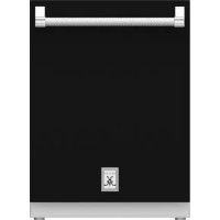
KDW24BK - Washing machine Hestan - Free user manual and instructions
Find the device manual for free KDW24BK Hestan in PDF.


User questions about KDW24BK Hestan
0 question about this device. Answer the ones you know or ask your own.
Ask a new question about this device
Download the instructions for your Washing machine in PDF format for free! Find your manual KDW24BK - Hestan and take your electronic device back in hand. On this page are published all the documents necessary for the use of your device. KDW24BK by Hestan.
USER MANUAL KDW24BK Hestan
natural_image
Black-and-white still life of wine glasses and a series of tiered plates, no text or symbols visibleINDOOR CLEANING
Dishwasher
KDW
Installation Manual
WARNING
IF THE INFORMATION IN THIS MANUAL IS NOT FOLLOWED EXACTLY, A FIRE OR EXPLOSION MAY RESULT CAUSING PROPERTY DAMAGE, PERSONAL INJURY, OR DEATH.
Do not store or use gasoline or other flammable vapors and liquids in the vicinity of this or any other appliance.
Installation and service must be performed by a qualified installer or service agency.
DO NOT REPAIR, REPLACE OR REMOVE ANY PART OF THE APPLIANCE UNLESS SPECIFICALLY RECOMMENDED IN THE MANUAL. IMPROPER INSTALLATION, SERVICE OR MAINTENANCE CAN CAUSE INJURY OR PROPERTY DAMAGE. REFER TO THIS MANUAL FOR GUIDANCE. ALL OTHER SERVICING SHOULD BE DONE BY A QUALIFIED TECHNICIAN.
READ THESE INSTRUCTIONS CAREFULLY AND COMPLETELY BEFORE INSTALLING OR USING YOUR APPLIANCE TO REDUCE THE RISK OF FIRE, BURN HAZARD, OR OTHER INJURY. KEEP THIS MANUAL FOR FUTURE REFERENCE.
SAFETY DEFINITIONS

DANGER. THIS INDICATES INFORMATION AND WARNINGS WHICH, IF NOT OBSERVED, MAY COMPROMISE PERSONAL SAFETY OR DAMAGE THE APPLIANCE.

DANGER OF ELECTROCUTION. THIS INDICATES INFORMATION AND WARNINGS OF AN ELECTRICAL NATURE WHICH, IF NOT OBSERVED, MAY COMPROMISE PERSONAL SAFETY OR DAMAGE THE APPLIANCE.

THIS HIGHLIGHTS GENERAL INFORMATION AND WARNINGS AND INDICATES THAT DAMAGE TO THE APPLIANCE OR PROPERTY MAY OCCUR AS A RESULT OF NOT OBSERVING THIS WARNING.
INSTALLER: LEAVE THIS MANUAL WITH THE OWNER OF THE APPLIANCE. HOMEOWNER: RETAIN THIS MANUAL FOR FUTURE REFERENCE.
TABLE OF CONTENTS
1 SAFETY PRECAUTIONS - BEFORE YOU BEGIN
2 MODEL NUMBERS
2 RATING LABEL
2 REGULATORY / CODE REQUIREMENTS
3 LOCATION AND INSTALLATION
12 MOUNTING THE OVERLAY DOOR PANEL
13 ATTACHING THE SIDE GASKETS
14 COMPLETING INSTALLATION AND TESTING
15 ELECTRICAL CONNECTIONS, SAFETY AND CAUTION
SAFETY PRECAUTIONS - BEFORE YOU BEGIN
When properly cared for, your Hestan appliance will provide safe, reliable service for many years. When using this appliance, basic safety practices must be followed as outlined below.
IMPORTANT: Save these instructions for the local Utility Inspector's use.
INSTALLER: Please leave these Installation Instructions with the owner.
OWNER: Please retain these Installation Instructions for future reference.
This appliance is NOT designed for installation in manufactured (mobile) homes or recreational park trailers. Do NOT install this appliance outdoors.
WARNING
ELECTRICAL SHOCK HAZARD
Disconnect power before installing or servicing appliance. Before turning power ON, be sure all controls are in the OFF position. Failure to do so can result in death or electrical shock.
natural_image
Silhouette of a person in motion with a curved arrow, no text or symbols presentELECTRICAL GROUNDING
- This appliance must be grounded. Grounding reduces the risk of electric shock in the event of a short circuit. Read the ELECTRICAL CONNECTIONS section of this manual for complete instructions.
• DO NOT ground to a gas pipe. - DO NOT use an extension cord with this appliance.
- DO NOT have a fuse in the NEUTRAL or GROUNDING circuit. A fuse in the NEUTRAL or GROUNDING circuit could result in an electrical shock.
MODEL NUMBERS
DISHWASHER MODELS
| Model No. Description Circuit Breaker Req'd | |
| KDW24 24" Dishwasher, Stainless Door 15 Amp | |
| KDW24-OV 24" Dishwasher, Overlay Door 15 Amp | |
| KDW24-XX | 24" Dishwasher, Color Door 15 Amp |
NOTE: -XX indicates color model.
-BK for Stealth - Black
-WH for Froth - White
-RD for Matador - Red
-YW for Sol - Yellow
-OR for Citra - Orange
-BG for Tin Roof - Burgundy
-PP for Lush - Purple
-BU for Prince - Blue
-GR for Grove - Green
-GG for Pacific Fog - Graphite Gray
-TQ for Bora Bora - Turquoise
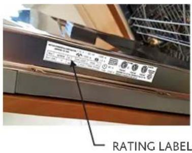
RATING LABEL
The rating label contains important information about your Hestan appliance such as the model and serial number and electrical rating.
The rating label is located on the right side of the door edge.
If service is necessary, contact Hestan Customer Care with the model and serial number information shown on the label.
text_image
RATING LABEL
text_image
HESTAN COMMERCIAL CORPORATION 115 V - 60 Hz 1080 W ANAHEIM, CA. - USA 1000 W 13 A Mod KDW24 SI S/N ZZZZZ XXXX Y Full S/N Y COD MACCHINA ZZZZZ XXXX 03 00 M 80 W Type: 12162 A CONFORMS TO UL STD 749, CONFORMS TO NSF STD 184, CERTIFIED TO CAN/CSA STD C22.2 NO.167 CH 3134823 CH 5007283 CANADIAN ENERGY PERFORMANCE VERIFIED INVERTAK INVERTAK INVERTAK RENDEMENT ENERGétique VERIFIEDTYPICAL RATING LABEL
REGULATORY/CODE REQUIREMENTS
Installation of this dishwashing appliance must be made in accordance with local codes. In the absence of local codes, this unit should be installed in accordance with the National Electrical Code and local codes.
This appliance must be electrically grounded in accordance with local codes or in the absence of local codes with the National Electrical Code ANSI/NFPA 70, or Canadian Electrical code CSA C22.1
UNPACKING AND PLACEMENT
Remove the outer carton and packing materials Do not remove the plastic film covering the stainless-steel surfaces. This film protects the finish from scratches until the appliance is installed in its final position.
The unit is heavy and should be handled with care. Use proper safety equipment, such as gloves and 2 persons to move the appliance into position to avoid injury and to avoid damage to the floor or the appliance itself.
NOTICE
DO NOT USE A HAND TRUCK OR DOLLY ON THE FRONT OR REAR OF THE DISHWASHER. HANDLE AND MOVE FROM THE SIDES ONLY.
Do not lift or carry the appliance by the door or handle. This could damage the door hinges.
PREPARATION
Before moving the dishwasher, protect any finished flooring and secure the door closed to prevent damage. DO NOT lift the dishwasher by the door handle.
Make sure that power can be provided to the location selected.
TOOLS
The following tools are needed for the installation of the dishwasher:
- Tape measure and straight edge or ruler
- Pencil
• Philips screw driver - Level
- Plumbing pliers
- Hand or saber saw
• 13mm open-end or adjustable wrench - File
- Drill and drill bit
• Safety gloves and goggles
STEPS FOR INSTALLATION
The following pages provide the necessary information for proper installation of the dishwasher and are arranged as follows:
- Technical data.
- Installation cutout dimensions, required clearances and mounting instructions.
• Electrical requirements and connections. - Leak inspection and testing.
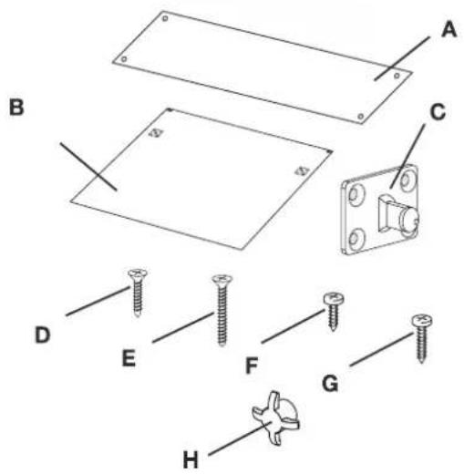
INSTALLATION KIT SUPPLIED WITH DISHWASHER
The kit supplied with the dishwasher comprises:
(KDW24-OV model also contains B, C, D, and E)
• 1 steel adhesive steam guard (A)
• 1 template for door panel (B)
• 2 hooks for door panel (C)
- 8 screws for securing the door panel hooks (D)
- 2 screws for securing the door (E)
- 4 screws for fixing the dishwasher to the adjacent walls (F)
• 2 upper fixing screws (G)
- 2 screw caps (H)
text_image
Technical diagram showing exploded view of a mechanical assembly with labeled parts A through H and screw placementsPRODUCT / CUT-OUT DIMENSIONS
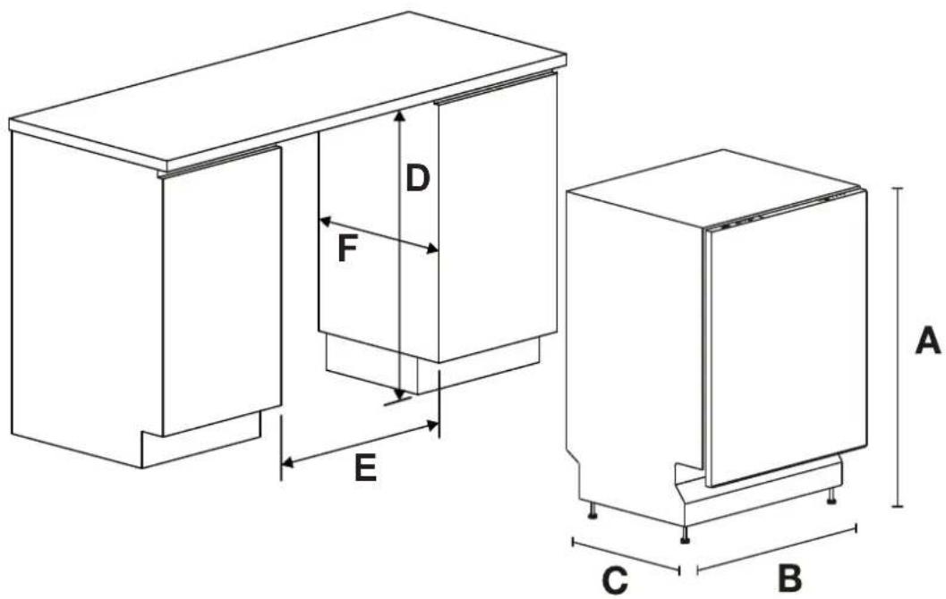
Product Dimensions:
| A (height) | B (width) | C (depth) |
| 32-9/32" - 35-3/64"82 cm - 89 cm | 23-1/2" ÷ 23-37/64"59.7 cm ÷ 59,9 cm | 21-21/32"55 cm |
Cut-out Dimensions:
| D (height) E (width) | F (depth) | |
| 33-7/8” height86.1 cm | 23-11/16” wide60.2 cm | 22-5/8” min depth57.5 cm |
text_image
D F E C B ACAUTION

DURING INSTALLATION, TAKE CARE NOT TO INJURE YOURSELF ON THE SHARP EDGES OF THE APPLIANCE.
Remove the polystyrene rack blocks. Position the appliance in the chosen installation position. The sides and rear of the appliance can lie against kitchen units or walls. If the dishwasher is installed next to a heat source, separate it with a heat insulating panel in order to prevent overheating and malfunctions.

BUILDING-IN A DISHWASHER BELOW A COOKTOP IS ABSOLUTELY FORBIDDEN. A DISHWASHER CAN BE BUILT-IN UNDERNEATH A CONVENTIONAL HOB PROVIDED THERE IS NO BREAK IN THE KITCHEN WORKTOP, AND THE DISHWASHER AND HOB ARE INSTALLED AND SECURED CORRECTLY, SO THAT NO HAZARDS ARE GENERATED.

MAKE SURE THE DISHWASHER HAS BEEN CORRECTLY INSTALLED AND GROUNDED BY A QUALIFIED FITTER. THIS SAFETY REQUIREMENT MUST BE MET. IN CASE OF DOUBT, CALL IN A QUALIFIED FITTER. THE MANUFACTURER DECLINES ALL RESPONSIBILITY FOR DAMAGE TO PERSONS OR PROPERTY RESULTING FROM THE FAILURE TO GROUND THE APPLIANCE OR FROM A DEFECTIVE GROUND CONNECTION.

BEFORE PROCEEDING WITH INSTALLATION, DISCONNECT THE MAINS POWER SUPPLY FROM THE WORK AREA.
LEVELING
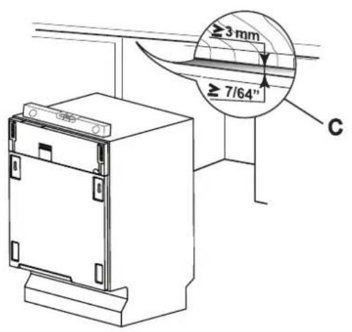
Level the appliance using the adjustable feet on the bottom. Use an open-ended wrench or socket to rotate the feet until the dishwasher is perfectly level. The rear foot can be adjusted with a 8 mm wrench or socket. Use a level to be certain the dishwasher is perfectly level. Leveling is vital for assuring correct dishwasher operation. Make sure to leave a gap of at least 7/64" (3mm) between the top of the dishwasher and the bottom surface of the countertop.
text_image
≥ 3 mm ≥ 7/64" C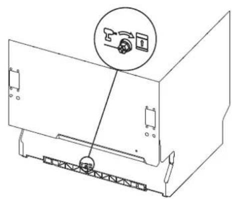
natural_image
Technical line drawing of a device casing with a close-up inset showing a lock mechanism (no text or symbols)ELECTRICAL AND WATER CONNECTIONS
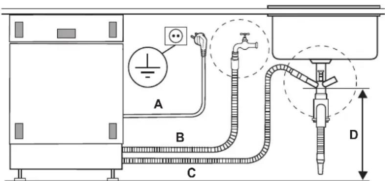
Install the dishwasher to allow ease of access to the electrical and water connections through the adjacent cabinetry. These connections must never be behind the dishwasher.
The inlet and drain hoses can be pointed in all directions but make sure that they are not bent, crushed or too tight. Tighten the ring nut after pointing the hoses in the required direction.
The illustration below indicates the distances to maintain between the dishwasher and the various connections.

FIRE HAZARD!
DO NOT COVER OR CRUSH THE CORD PLUG.
text_image
A B C DA = \~47" / 1200mm
B = \~59" / 1500mm
C = \~63" / 1600mm
D = min. 16" / 400mm
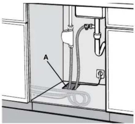
A through hole with a diameter of at least 5/32" (8mm) is required to pass the hoses and power cord.
Make sure there are no rough edges that could damage the power cord or hoses. If the dishwasher is installed in a metal unit protect the edge of the through hole for the hoses and power cord with a gasket. Do not use extension cords when making the electrical connection as these do not guarantee safety.

ATTENTION!
INSTALLING THE DISHWASHER IN A NARROW SPACE MAY BEND OR CRUSH THE POWER CORD. TAKE GREAT CARE IN ORDER TO REDUCE THE POSSIBILITY OF DAMAGING THE POWER CORD WHEN INSTALLING OR REMOVING THE APPLIANCE.
CONNECTING THE WATER SUPPLY

PREVENTING THE RISK OF CLOGGING OR DAMAGE:
IF THE PLUMBING IS NEW OR HAS NOT BEEN USED FOR A LONG TIME TIME, BEFORE CONNECTING TO THE WATER SUPPLY CHECK THAT THE WATER IS CLEAR AND FREE OF IMPURITIES, TO PREVENT DAMAGE TO THE APPLIANCE. THE DISHWASHER MUST ALWAYS BE CONNECTED TO THE THE WATER SYSTEM WITH NEW HOSES. OLD OR USED HOSES MUST NEVER BE RE-USED.
natural_image
Interior view of a kitchen sink with labeled component A, showing piping and tubing (no text or symbols beyond label)CONNECTING TO A WATER TAP
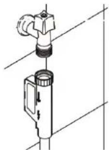
Connect the inlet hose to a threaded 3/4" cold water tap fitting the supplied filter. Firmly secure the hose by tightening the relative ring nut with your hands; finish by tightening another 1/4 turn using a pair of plumbing pliers.
The dishwasher can be filled with water at a temperature of less than 140^ F 60^ C. If the appliance is filled with hot water, washing times will be reduced by about 20 minutes, but efficiency will be slightly impaired. Make the connection to the domestic hot water tap using the same methods described for connecting the appliance to the cold water tap.
- Recommended temperature: 49^ (120°F), max. 60^ (140°F).
• Recommended water pressure: 0.5 - 9 bar (7 - 130 PSI).
If the pressure is too high, use a pressure reducer.
A rubber hose connected to a sink spray may burst if installed on the same pipes feeding the dishwasher. If your sink is fitted with this accessory, remove the hose and plug the hole.
natural_image
Technical line drawing of a faucet and mechanical component (no text or symbols)EN
CONNECTING TO A WATER TAP (continued)
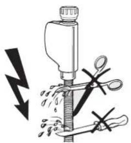
Do not cut the inlet hose.
If the hose is cut, the dishwasher will not work, water will leak and you may be injured. If the hose is too long, wind it up neatly and place it behind the appliance. The cable harness and electrical components must not come into contact with the hydraulic system and the water inlet and drain hoses.
natural_image
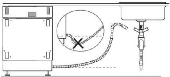
Illustration of a mechanical device with scissors and forceps, showing no text or symbolsWhen connecting the dishwasher drain hose to the sink make sure that the hose is not bent in order to prevent cracks or breakages that could damage it.
natural_image
Technical line drawing of a mechanical assembly with a circular component and tubing (no text or symbols)CONNECTING TO A "T" UNION FOR DRAINAGE

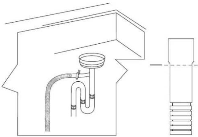
MAKE THE CONNECTION UPLINE FROM THE SIPHON OF THE DRAIN LINE AND AT LEAST 400 mm (15-3/4") ABOVE THE FLOOR ON WHICH THE DISHWASHER WILL BE INSTALLED.
Connect the dishwasher drain hose to the "T" union of the drain using a 1-1/2 to 2" (38 to 50 mm) screw clamp* if necessary, cut the end of the dishwasher drain hose (DO NOT cut the corrugated section).
* Available from any plumbing store
natural_image
Technical line drawing of a plumbing fixture with pipes and a sink (no text or symbols)CONNECTING TO A WASTE DISPOSAL UNIT WITH AN AIR GAP

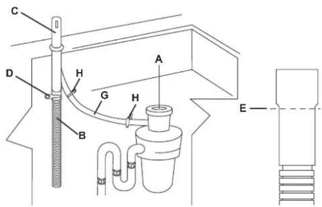
MAKE THE CONNECTION UPLINE FROM THE SIPHON OF THE DRAIN LINE AND AT LEAST 15-3/4" (400 mm) ABOVE THE FLOOR ON WHICH THE DISHWASHER WILL BE INSTALLED.
- Remove the cover of the waste disposal unit (A).
- Connect the dishwasher drain hose (B) to the air gap (C) using the wide spring clamp (D); if necessary, cut the end of the dishwasher drain hose (E) (do not cut the corrugated section). If the drain hose has been cut, use a 38 to 50 mm (1-1/2 to 2") screw clamp*.
- To connect the air gap (ref. C) to the waste disposal unit inlet (F) use a rubber union* (G) with spring or screw clamps*
* Available from any plumbing store
text_image
C D H G A B H ECONNECTING TO THE AIR GAP WITHOUT A WASTE DISPOSAL UNIT

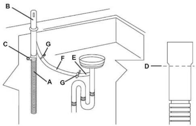
MAKE THE CONNECTION UPLINE FROM THE SIPHON OF THE DRAIN LINE AND AT LEAST 15-3/4" (400 mm) ABOVE THE FLOOR ON WHICH THE DISHWASHER WILL BE INSTALLED
- Connect the dishwasher drain hose (ref. B) to the air gap (C) using the wide spring clamp (D); if necessary, cut the end of the dishwasher drain hose (E) (do not cut the corrugated section). If the drain hose has been cut, use a 38 to 50 mm (1-1/2 to 2") screw clamp*.
- To connect the air gap (ref. C) to the waste disposal unit inlet (F) use a rubber union* (G) with spring or screw clamps*
* Available from any plumbing store
text_image
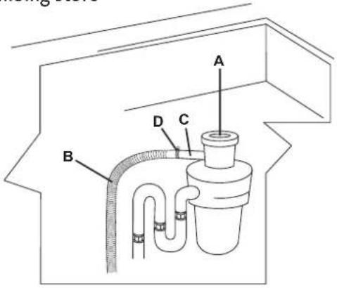
B C G F E A G DCONNECTING TO A WASTE DISPOSAL WITHOUT AN AIR GAP

MAKE THE CONNECTION UPLINE FROM THE SIPHON OF THE DRAIN LINE AND AT LEAST 15-3/4" (400 mm) ABOVE THE FLOOR ON WHICH THE DISHWASHER WILL BE INSTALLED.
-
Remove the cover of the waste disposal unit (A).
-
Connect the dishwasher drain hose (B) to the waste disposal unit inlet (C), using the wide spring clamp (D).
* Available from any plumbing store
text_image
A B C DCONNECTING TO THE OUTLET

CHECK THAT VOLTAGE AND FREQUENCY OF THE OUTLET MATCHES THE RATINGS ON THE NAME PLATE OF THE APPLIANCE, WHICH IS POSITIONED ON THE INNER EDGE OF THE DOOR.

IN THE EVENT OF DAMAGE TO THE SUPPLY CORD, HAVE IT REPLACED BY THE MANUFACTURER OR AN AUTHORIZED TECHNICIAN. THIS APPLIANCE MUST BE GROUNDED. IN CASE OF A MALFUNCTION OF FAULT, THE GROUND REDUCES THE RISK OF ELECTROCUTION BY BY PROVIDING THE ELECTRICAL CURRENT WITH AN ALTERNATIVE, LESS RESISTANT PATH. THIS APPLIANCE IS FITTED WITH A POWER CORD CONTAINING A GROUND WIRE AND PLUG. FIT THE PLUG INTO A SUITABLE OUTLET, INSTALLED AND GROUNDED IN COMPLIANCE WITH LOCAL CODE.

BEFORE MAKING ELECTRICAL CONNECTIONS, DISCONNECT THE MAIN POWER SUPPLY FROM THE WORK AREA.

WARNING AN INCORRECTLY CONNECTED GROUND WIRE MAY GENERATE THE RISK OF ELECTROCUTION. IF IN DOUBT AS TO THE CORRECT GROUNDING OF THE APPLIANCE, CALL IN A QUALIFIED ELECTRICIAN OR THE TECHNICAL ASSISTANCE SERVICE. DO NOT CHANGE THE PLUG ATTACHED TO THE APPLIANCE.

THE PLUG AT THE END OF THE POWER CORD AND THE CORRESPONDING OUTLET MUST BE OF THE SAME TYPE AND MUST CONFORM TO LOCAL REGULATIONS GOVERNING ELECTRICAL APPLIANCES. NEVER REMOVE THE PLUG BY PULLING ON THE CORD.
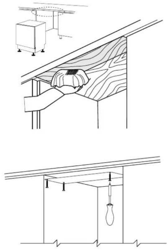
RECOMMENDED CONDENSATION PROTECTION
Clean the front 6" of the underside of the countertop directly above the door. Apply the steam guard, as shown below. The guard protects the countertop from steam and condensation when the door of the dishwasher is opened at the end of the washing cycle.
natural_image
Technical line drawings of ceiling fixtures and structural components (no text or symbols)MOVE THE DISHWASHER INTO PLACE
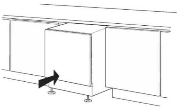
Push the dishwasher into position, taking care not to twist or crush the power cord or hoses.

TWO PEOPLE WEARING SAFETY GLOVES ARE NEEDED TO PUSH THE DISHWASHER INTO PLACE.
natural_image
Pure technical line drawing of a cabinet or enclosure structure with mounting feet and a directional arrow, no text or symbols present.MOUNTING THE OVERLAY DOOR PANEL (KDW24-OV MODEL)
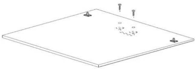
Place the provided template on the inner surface of the overlay panel. Center the template on the panel and align it with the top edge, matching up the reference locators (A). . Mark the position of the door hooks with a pencil. Remove the template and use a drill with a suitable bit to carefully make holes at the points marked on the panel. Using a Phillips screwdriver, secure the door hooks with the 8 supplied screws at the marked reference points.
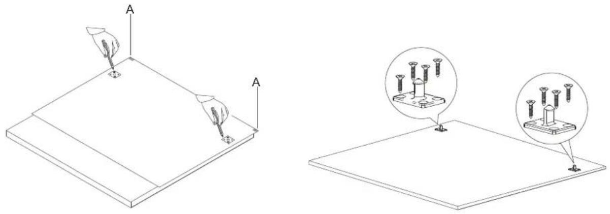
Drill the holes for the overlay panel handle using a drill with a suitable bit. Attach the door handle before securing the panel to the dishwasher (screws for mounting the handle are not provided).
natural_image
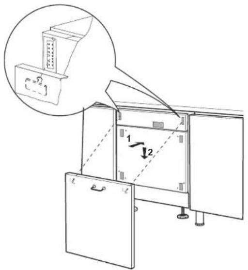
Isometric line drawing of a flat plate with three screw holes and three circular indentations on the surface (no text or symbols)Attach the door panel by fitting the hooks into their slots on the dishwasher and carefully slide the panel downwards and securely into place.
Make sure the dishwasher door, complete with panel, opens without restrictions.
text_image
Diagram showing a cabinet with labeled parts and an inset view of a cabinet with a handle, illustrating mechanical or electrical assembly.ATTACHING THE SIDE GASKETS
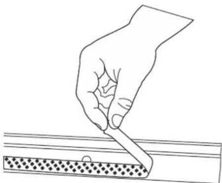
Before securing the dishwasher to the adjacent cabinetry, attach the gaskets to the sides of the dishwasher. Remove the adhesive band on the gasket.
natural_image
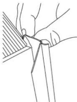
Line drawing of a hand holding a pen over a textured surface (no text or symbols)Fix the gasket to the dishwasher, inserting it in the seat on the sides towards the front, making sure that the long side of the gasket with the hole for inserting the screw, is attached to the outside of the dishwasher. The hole in the long side must match the hole in the dishwasher. Make sure the gasket is properly adhered to the dishwasher.
natural_image
Line drawing of hands holding a tool or tool with a ruler, no text or symbols present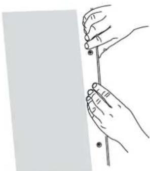
natural_image
Line drawing of a hand holding a pen or ruler against a plain background (no text or symbols)The illustration below shows the proper application of the side gasket.
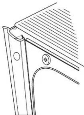
natural_image
Technical line drawing of a mechanical bracket or bracket assembly (no text or symbols)EN
COMPLETING THE INSTALLATION
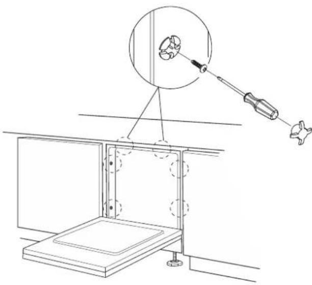
It is an important step to properly secure the dishwasher to the adjacent cabinetry or the underside of the countertop. Using the supplied screws, carefully secure the dishwasher to the cabinetry or countertop then cover the holes with the plugs provided.
natural_image
Technical line drawing of a mechanical assembly with a magnified circular component and tool, no text or symbols presentTESTING THE DISHWASHER
After installation, test the dishwasher by starting a work cycle. Check carefully for leaks and make sure the appliance does not malfunction.

THIS MANUAL IS AN INTEGRAL PART OF THE APPLIANCE: IT MUST ALWAYS BE KEPT INTACT TOGETHER WITH THE DISHWASHER. BEFORE USING THE APPLIANCE, CAREFULLY READ ALL THE INSTRUCTIONS CONTAINED IN THIS MANUAL. INSTALLATION MUST BE PERFORMED BY A QUALIFIED TECHNICIAN, IN COMPLIANCE WITH THE REGULATIONS IN FORCE. THIS APPLIANCE IS INTENDED FOR DOMESTIC USE AND SIMILAR APPLICATIONS SUCH AS THE STAFF KITCHENS OF SHOPS, OFFICES AND OTHER WORKPLACES, INSTITUTIONS, AND FOR THE USE OF GUESTS AT HOTELS, HOSTELS, BED AND BREAKFAST ESTABLISHMENTS AND OTHER RESIDENTIAL FACILITIES AND COMPLIES WITH DIRECTIVES 2006/95/EC AND 2004/108/ECCURRENTLY IN FORCE, INCLUDING THE PREVENTION AND ELIMINATION OF RADIO FREQUENCY INTERFERENCE. THE APPLIANCE IS DESIGNED FOR THE FOLLOWING PURPOSE: WASHING AND DRYING DISHES. ANY OTHER USE SHALL BE CONSIDERED IMPROPER. THE MANUFACTURER DECLINES ALL RESPONSIBILITY FOR USES OTHER THAN THOSE DESCRIBED ABOVE.

INSTALLATION, REPAIRS AND SERVICING MUST BE PERFORMED BY QUALIFIED AND AUTHORIZED TECHNICIANS. AS WELL AS INVALIDATING THE WARRANTY, WORK CARRIED OUT BY UNAUTHORIZED PERSONS MAY GENERATE HAZARDS. INSTALLATION MUST BE PERFORMED IN COMPLIANCE WITH ALL THE DIRECTIVES IN FORCE IN THE COUNTRY OF INSTALLATION AND, IF THESE DO NOT EXIST: IN THE UNITED STATES THE NATIONAL ELECTRIC CODE; IN CANADA THE CANADIAN ELECTRIC CODE C22.1 - LATEST EDITION/PROVINCIAL AND MUNICIPAL CODES AND/OR LOCAL CODES.

THE NAME PLATE FEATURING THE TECHNICAL DATA, SERIAL NUMBER AND MARKINGS IS VISIBLY POSITIONED ON THE INNER EDGE OF THE DOOR. THE NAMEPLATE ON THE INNER EDGE OF THE DOOR MUST NEVER BE REMOVED.

THIS APPLIANCE IS NOT SUITABLE FOR USE ON BOATS, CARAVANS OR THE LIKE. DISHWASHERS CERTIFIED FOR DOMESTIC USE ARE NOT SUITABLE FOR COMMERCIAL APPLICATIONS.

CHECK THAT THE VOLTAGE, FREQUENCY AND PROTECTION OF THE DOMESTIC MAIN POWER SUPPLY MATCH THE RATINGS ON THE NAME PLATE OF THE APPLIANCE.

TWO PEOPLE WEARING SAFETY GLOVES ARE REQUIRED TO LIFT THE DISHWASHER.

DO NOT LEAVE DISCARDED PACKAGING MATERIALS UNSUPERVISED WITHIN THE HOME. SEPARATE THE VARIOUS PACKAGING MATERIALS AND TAKE THEM TO THE NEAREST SORTED WASTE COLLECTION CENTRE. KEEP CHILDREN, PHYSICALLY AND/OR MENTALLY IMPAIRED ADULTS, AND ANIMALS AWAY FROM PACKAGING WASTE; DANGER OF SUFFOCATION.

BEFORE PROCEEDING WITH INSTALLATION, DISCONNECT THE MAIN POWER SUPPLY FROM THE WORK AREA.

DURING INSTALLATION, TAKE CARE NOT TO INJURE YOURSELF ON THE SHARP EDGES OF THE APPLIANCE; WEAR SAFETY GLOVES.

THE APPLIANCE MUST BE PROVIDE WITH A GROUNDED CONNECTION IN ACCORDANCE WITH THE ELECTRICAL SAFETY REGULATIONS IN FORCE. IF IN DOUBT, HAVE THE SYSTEM CHECKED BY A QUALIFIED ELECTRICIAN. THE MANUFACTURER DECLINES ALL RESPONSIBILITY FOR DAMAGE TO PERSONS OR PROPERTY RESULTING FROM THE FAILURE TO GROUND THE APPLIANCE OR FROM A DEFECTIVE GROUND CONNECTION.

DO NOT USE APPLIANCES WHICH HAVE BEEN DAMAGED DURING TRANSIT! IF IN DOUBT, CONSULT YOUR DEALER. THE APPLIANCE MUST BE INSTALLED AND CONNECTED IN ACCORDANCE WITH THE INSTRUCTIONS PROVIDED BY THE MANUFACTURER OR BY A QUALIFIED TECHNICIAN.

DO NOT OPERATE THE DISHWASHER UNLESS ALL OF THE OUTER PANELS HAVE BEEN POSITIONED CORRECTLY. IMMEDIATELY AFTER INSTALLATION, BRIEFLY TEST THE APPLIANCE FOLLOWING THE INSTRUCTIONS INDICATED BELOW. IF THE DISHWASHER FAILS TO OPERATE CORRECTLY, DISCONNECT IT FROM THE ELECTRICAL POWER SUPPLY AND CALL THE NEAREST TECHNICAL SERVICE CENTER. DO NOT ATTEMPT TO REPAIR THE APPLIANCE.

DO NOT USE EXTENSION CORDS OR ADAPTORS IN ORDER TO AVOID THE POSSIBILITY OF OVERHEATING OR BURNING, WITH THE CONSEQUENCE OF A FIRE HAZARD.

THE MANUFACTURER DECLINES ALL RESPONSIBILITY FOR DAMAGE TO PERSONS, ANIMALS OR PROPERTY RESULTING FROM FAILURE TO OBSERVE THE ABOVE PRECAUTIONS, FROM TAMPERING WITH EVEN A SINGLE COMPONENT OF THE APPLIANCE, OR FROM THE USE OF UNORIGINAL SPARE PARTS. IF IN DOUBT ABOUT THE CONTENTS OF THIS MANUAL, CONTACT TECHNICAL SERVICE.
⚠️ AVERTISSEMENT
LE NON-RESPECT À LA LETTRE DE CES INSTRUCTIONS PEUT CAUSER UN INCENDIE OU UNE EXPLOSION, QUI POURRAIT ENTRAÎNER DES DOMMAGES MATÉRIELS, DES BLESSURES OU LA MORT.
natural_image
Silhouette of a person in motion with a curved arrow, no text or symbols present-WH for Froth - Blanc
-RD for Matador - Rouge
-YW for Sol - Jaune
-OR for Citra - Orange
-BG for Tin Roof - Bourgogne
-PP for Lush - Violet
-BU for Prince - Bleu
-GR for Grove - Vert
-GG for Pacific Fog - Gris graphite
-TQ for Bora Bora - Turquoise
ÉTIQUETTE DE NOTATION
text_image
Technical diagram showing labeled components of a mechanical assembly with pins and parts A through HDIMENSIONS DE PRODUIT / DE COUPE
text_image
Technical diagram of a device with labeled components and an inset showing a close-up view of a connector or switch.CONNECTING THE WATER SUPPLY
FR

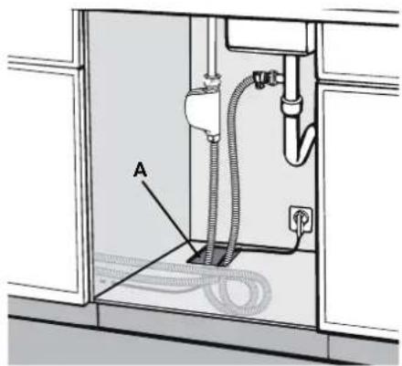
PRÉVENTION DU RISQUE D'OBSTRUCTION OU DE DOMMAGE:
SI LA PLOMBERIE EST NOUVELLE OU N'EST PAS UTILISÉE LONGTEMPS
HEURE, AVANT DE RACCORDER AU VERIFICATION DE L'ALIMENTATION EN EAU
L'EAU EST CLAIR ET LIBRE D'IMPURETÉS POUR PRÉVENIR LES DOMMAGES
APPAREIL. LE LAVE-VAISSELLE DOIT TOUJOURS ÊTRE CONNECTÉ AU
LE SYSTÈME D'EAU AVEC DE NOUVEAUX TUYAUX. LES TUYAUX VIEUX OU UTILISÉS DOIVENT NE JAMAIS ÊTRE RÉUTILISÉ.
natural_image
Technical diagram of a kitchen sink with labeled component A, showing piping and electrical connections (no text or symbols beyond label)RACCORDEMENT À UN ROBINET D'EAU
The dishwasher can be filled with water at a temperature of less than 140°F 60°C.
natural_image
Technical line drawing of a mechanical assembly with a valve and cylindrical component (no text or symbols)RACCORDEMENT À UN ROBINET D'EAU (a continué)
natural_image
Illustration of a mechanical device with forceps and a downward arrow indicating compression or damage (no text or symbols)natural_image
Technical diagram of a mechanical or electrical setup with a device, tubing, and a circular inset showing a cross symbol (no text or labels present)RACCORDEMENT À UNE UNION "T" POUR LE DRAINAGE

RENDRE LA LIGNE DE CONNEXION AU SIPHON DU DRAIN LINE ET AU MOINS 400 mm (15-3 / 4") AU-DESSUS DU PLANCHER SUR LEQUEL LE LAVE-VAISSELLE SERA INSTALLE.
natural_image
Technical line drawing of a plumbing fixture with tubing and a sink (no text or symbols)CONNECTING TO A WASTE DISPOSAL UNIT WITH AN AIR GAP

RENDRE LA LIGNE DE CONNEXION AU SIPHON DU DRAIN LINE ET AU MOINS 15-3 / 4" (400 mm) AU-DESSUS DU PLANCHER SUR LEQUEL LE LAVE-VAISSELLE SERA INSTALLE.
text_image
C D H G A B H ERACCORDEMENT À L'AIR GAP SANS UNITÉ D'ÉLIMINATION DES DÉCHETS

RENDRE LA LIGNE DE CONNEXION AU SIPHON DU DRAIN LINE ET AU MOINS 15-3 / 4"(400 mm) AU-DESSUS DU PLANCHER SUR LEQUEL LE LAVE-VAISSELLE SERA INSTALLE
text_image
B C G F E A G DRACCORDEMENT À UNE ÉLIMINATION DES DÉCHETS SANS ÉCART D'AIR

RENDRE LA LIGNE DE CONNEXION AU SIPHON DU DRAIN LINE ET AU MOINS 15-3 / 4 "(400 mm) AU-DESSUS DU PLANCHER SUR LEQUEL LE LAVE-VAISSELLE SERA INSTALLE.
natural_image
Pure architectural line drawing of two adjacent rectangular panels with a directional arrow indicating movement or force (no text or symbols)MONTAGE DU PANNEAU DE PORTE DE RECOUVREMENT (MODELE KDW24-OV)
natural_image
Technical line drawings showing two views of a flat surface with screw fasteners, one with magnified insets (no text or symbols)natural_image
Simple line drawing of a rectangular plate with four small screws and three circular holes, no text or symbols present.text_image
Diagram showing a cabinet with labeled parts and an inset image of a cabinet with a magnified view.FIXATION DES JOINTS LATÉRAUX
natural_image
Line drawing of a hand holding a tool over a textured surface (no text or symbols)natural_image
Line drawing of hands holding a tool or tool with a ruler, no text or symbols present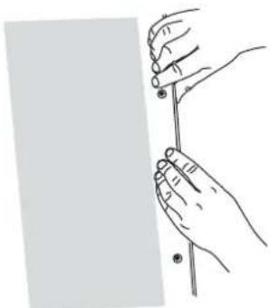
natural_image
Line drawing of two hands holding a thin rod against a plain background (no text or symbols)natural_image
Technical line drawing of a mechanical bracket or bracket assembly (no text or symbols)TERMINER L'INSTALLATION
natural_image
Technical line drawing of a mechanical assembly with a magnified circular component and tool, no text or symbols presentTESTER LA LAVE-VAISSELLE
Hestan Commercial Corporation
3375 E. La Palma Ave
Anaheim, CA 92806
(888) 905-7463
©2018 Hestan Commercial Corporation P/N 020060 REV A