
HBS20X - Saw DEXTER - Free user manual and instructions
Find the device manual for free HBS20X DEXTER in PDF.
| Brand | DEXTER |
| Model | HBS20X |
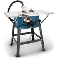
| Product type | Band saw |
| Power supply | 230-240 V ~ 50 Hz |
| Power (S1 / S2 30 min) | 250 W / 350 W |
| No-load speed | 1400 min-1 |
| Band speed | 900 m/min |
| Band length | 1400 mm |
| Band width | 6 - 12 mm |
| Max. cutting height | 80 mm |
| Throat depth | 200 mm |
| Table dimensions (without extension) | 300 x 300 mm |
| Table dimensions (with max. extension) | 535 x 300 mm |
| Table tilt | 0° to 45° |
| Max. workpiece dimensions | 400 x 400 x 80 mm |
| Weight | 19 kg |
| Sound pressure level LpA | 77.4 dB (uncertainty 3 dB) |
| Sound power level LwA | 90.4 dB (uncertainty 3 dB) |
| Main functions | Rip cuts, bevel cuts, freehand cuts, cross cuts (with optional miter gauge) |
| Safety | Anti-restart safety switch, blade guard, locking cover, disconnector protection device |
| Maintenance and cleaning | Regular cleaning of extraction channels, replacement of worn table insert, changing the saw blade, no lubrication required |
| Spare parts and repairability | Wear parts: carbon brushes, saw blade, table inserts, V-belts. Repairs by approved specialist. |
| General information | 24-month warranty for domestic use, manufacturer: ADEO Services, 135 rue Sadi Carnot, 59790 Ronchin, France |
Frequently Asked Questions - HBS20X DEXTER
User questions about HBS20X DEXTER
0 question about this device. Answer the ones you know or ask your own.
Ask a new question about this device
Download the instructions for your Saw in PDF format for free! Find your manual HBS20X - DEXTER and take your electronic device back in hand. On this page are published all the documents necessary for the use of your device. HBS20X by DEXTER.
USER MANUAL HBS20X DEXTER
Explanation of the symbols on the device
| Warning! Disregard results in a risk of death or injury, or damage to the tool! | |
| Read the operating and safety instructions before start-up and follow them! | |
| Wear eye protection. | |
| Wear hearing protection. | |
| If dust builds up, wear respiratory protection! | |
| Attention! Risk of injury! Do not reach into saw blade while it is running! | |
| Wear protective gloves. | |
| Attention! Before assembly, cleaning, modification, servicing, storage and transport, the device must be switched off and disconnected from the power supply. | |
| Saw band direction | |
| The product complies with the applicable European directives. |
Table of contents: Page:
- Introduction 25
- Device description (Fig. 1-1b). 25
- Scope of delivery 26
- Proper use 26
- Safety information 26
- Technical data 29
- Before commissioning 29
- Assembly 29
- Operation 32
- Working instructions 32
- Electrical connection 34
- Cleaning, maintenance and storage 34
- Disposal and recycling 34
- Transport 35
- Troubleshooting 36
16.Declaration of conformity. 55
1. Introduction
Manufacturer:
Adeo Services
We hope your new tool brings you much enjoyment and success.
Note:
In accordance with the applicable product liability laws, the manufacturer of this device assumes no liability for damage to the device or caused by the device arising from:
- Improper handling,
- Failure to comply with the operating instructions.
- Repairs carried out by third parties, unauthorised specialists.
- Installing and replacing non-original spare parts,
Application other than specified, - Failure of the electrical system in the event of the electrical regulations and VDE provisions 0100, DIN 13 / VDE0113 not being observed.
Please consider:
Read through the complete text in the operating manual before installing and commissioning the device.
This operating manual should help you familiarise yourself with your power tool and teach you how to use it for its intended purpose.
The operating manual include important instructions for the safe, proper and economic operation of the power tool, for avoiding danger, for minimising repair costs and downtimes and for increasing the reliability and extending the service life of the power tool.
In addition to the safety instructions in this operating manual, you must also observe the regulations applicable to the operation of the power tool in your country.
Keep the operating manual package with the power tool at all times and store it in a plastic cover to protect it from dirt and moisture. They must be read and carefully observed by all operating personnel before starting the work. The power tool may only be used by personnel who have been trained to use it and who have been instructed with respect to the associated hazards. The required minimum age must be observed.
In addition to the safety instructions in this operating manual and the separate regulations of your country, the generally recognised technical rules for operating woodworking machines must also be observed.
We accept no liability for accidents or damage that occur due to a failure to observe this manual and the safety instructions.
2. Device description (Fig. 1-1b)
- Clamping screw
- Top saw band roller
- Rubber surface
- Saw band guard
- Top saw band guide
- Table inlay
- Saw table
- Table width extension
- Bottom saw band roller
- Clamping lever
- Supporting foot
- Cover locking mechanism
- Side cover
- Parallel stop
- On/off switch
- Locking screw for top saw band roller
- Set screw for top saw band roller
- Machine frame
- Mains cable
- Motor
- Wing nut
- Locking handle for saw table
- Clamping plate
- Extraction port
- Transverse cutting gauge (optionally)
- Saw band
- Adjustment handle for saw band guide
- Locking handle for saw band guide
- Push stick
- 5mm Allen key
- 4mm Allen key
- 3mm Allen key
- Screwdriver
- SW10/13 open-ended spanner
- Degree scale for swivel range
- Screw M6x35
37.Washer M6 - Nut M6
- Screw M5x7
- Serrated washer M5
- Knurled nut for parallel stop
- Parallel stop clamping lever
- Guide rail for parallel stop
- Sight glass
- Allen screw for top support bearing
- Top support bearing
- Top guide pin
- Allen screw for top guide pins
- Retainer (top)
- Allen screw top retainer (2x)
- Allen screw bottom support bearing
- Bottom support bearing
- Screw bottom retainer
- Saw band protection
- Allen screw for bottom guide pins
-
Bottom guide pin
-
Retainer (bottom)
- Screw (saw table adjustment)
- Nut (saw table adjustment)
- Push rod retainer
3. Scope of delivery
- Open the packaging and carefully remove the device.
- Remove the packaging material, as well as the packaging and transport safety devices (if present).
- Check whether the scope of delivery is complete.
- Check the device and accessory parts for transport damage.
- If possible, keep the packaging until the expiry of the warranty period.
ATTENTION! The device and the packaging are not children's toys! Do not let children play with plastic bags, films or small parts! There is a danger of choking or suffocating!
1x Band saw
1x Saw table (7)
1x Table width extension (8) with guide rail (43)
1x Parallel stop (14)
1x Push stick (29)
1x Open-end spanner, size 10/13 (34)
3x Allen key 3mm (32)/4mm(31)/5mm (30)
1x Screw M6x35 (36)
1x Washer M6 (37)
1x Nut M6 (38)
2x Screws M5x7 (39)
2x Serrated washers M5 (40)
1x Operating manual
4. Proper use
The band saw is used for the longitudinal and transverse cutting of timbers or wood-like workpieces. Round materials may only be cut using suitable holding devices.
The machine may only be used in the intended manner. Any use beyond this is improper. The user/operator, not the manufacturer, is responsible for damages or injuries of any type resulting from this.
Only saw bands that are suitable for the machine may be used. An element of the intended use is also the observance of the safety instructions, as well as the assembly instructions and operating information in the operating manual.
Persons who operate and maintain the machine must be familiar with the manual and must be informed about potential dangers.
In addition, the applicable accident prevention regulations must be strictly observed. Other general occupational health and safety-related rules and regulations must be observed.
The liability of the manufacturer and resulting damages are excluded in the event of modifications of the machine.
Despite use as intended, specific risk factors cannot be entirely eliminated. Due to the design and layout of the machine, the following risks remain:
- Hearing damage when the necessary hearing protection is not used.
- Harmful emissions of wood dusts during use in enclosed areas.
- Risk of accident due to contact with the hands in the uncovered cutting area of the tool.
- Danger of injury during a tool change (cutting hazard).
- Danger due to the ejection of workpieces or parts of the workpiece.
- Crushing of fingers.
- Danger due to kick-back.
- Tilting of the workpiece due to insufficient workpiece support surface.
- Touching the cutting tool.
- Ejection of branches and workpiece parts.
Please observe that our equipment was not designed with the intention of use for commercial or industrial purposes. We assume no guarantee if the equipment is used in commercial or industrial applications, or for equivalent work.
5. Safety information
General safety information for electric tools
WARNING: Read all safety warnings, instructions, illustrations and specifications provided with this power tool.
Failure to follow all instructions listed below may result in electric shock, fire and/or serious injury.
Save all warnings and instructions for future reference.
The term "power tool" in the warnings refers to your mains-operated (corded) power tool or battery-operated (cordless) power tool.
1) Work area safety
a) Keep your work area clean and well-lit. Cluttered or dark areas invite accidents.
b) Do not operate power tools in explosive atmospheres, such as in the presence of flammable liquids, gases or dust. Power tools create sparks which may ignite the dust or fumes.
c) Keep children and bystanders away while operating a power tool. Distractions can cause you to lose control.
2) Electrical safety
a) Power tool plugs must match the outlet. Never modify the plug in any way. Do not use any adapter plugs with earthed (grounded) power tools. Unmodified plugs and matching outlets will reduce risk of electric shock.
b) Avoid body contact with earthed or grounded surfaces, such as pipes, radiators, ranges and refrigerators. There is an increased risk of electric shock if your body is earthed or grounded.
c) Do not expose power tools to rain or wet conditions. Water entering a power tool will increase the risk of electric shock.
d) Do not abuse the cord. Never use the cord for carrying, pulling or unplugging the power tool. Keep cord away from heat, oil, sharp edges or moving parts. Damaged or entangled cords increase the risk of electric shock.
e) When operating a power tool outdoors, use an extension cord suitable for outdoor use. Use of a cord suitable for outdoor use reduces the risk of electric shock.
f) If operating a power tool in a damp location is unavoidable, use a residual current device (RCD) protected supply. Use of an RCD reduces the risk of electric shock.
3) Personal safety
a) Stay alert, watch what you are doing and use common sense when operating a power tool. Do not use a power tool while you are tired or under the influence of drugs, alcohol or medication. A moment of inattention while operating power tools may result in serious personal injury.
b) Wear personal protective equipment and always safety goggles. Protective equipment such as a dust mask, non-skid safety shoes, safety helmet or hearing protection used for appropriate conditions will reduce personal injuries.
c) Prevent unintentional starting. Ensure the switch is in the off-position before connecting to power source and/or rechargeable battery, picking up or carrying the tool. Carrying power tools with your finger on the switch or energising power tools that have the switch on invites accidents.
d) Remove any adjusting tools or spanners/keys before turning the power tool on. A wrench or a key left attached to a rotating part of the power tool may result in personal injury.
e) Avoid abnormal postures. Keep proper footing and balance at all times. This enables better control of the power tool in unexpected situations.
f) Wear suitable clothing. Do not wear loose clothing or jewellery. Keep your hair and clothing away from moving parts. Loose clothes, jewellery or long hair can be caught in moving parts.
g) If devices are provided for the connection of dust extraction and collection facilities, ensure these are connected and properly used. Use of dust extraction can reduce dust-related hazards.
h) Do not let familiarity gained from frequent use of tools allow you to become complacent and ignore tool safety principles. A careless action can cause severe injury within a fraction of a second.
4) Power tool use and care
a) Do not force the power tool. Use the correct power tool for your application. The correct power tool will do the job better and safer at the rate for which it was designed.
b) Do not use the power tool if the switch does not turn it on and off. Any power tool that cannot be controlled with the switch is dangerous and must be repaired.
c) Disconnect the plug from the power source and/or remove the battery pack, if detachable, from the power tool before making any adjustments, changing accessories, or storing power tools. Such precautionary measures reduce the risk of starting the power tool accidentally.
d) Store idle power tools out of the reach of children and do not allow persons unfamiliar with the power tool or these instructions to operate the power tool. Power tools are dangerous in the hands of untrained users.
e) Maintain power tools and attachments. Check for misalignment or binding of moving parts, breakage of parts and any other condition that may affect the power tool's operation. If damaged, have the power tool repaired before use. Many accidents are caused by poorly maintained power tools.
f) Keep cutting tools sharp and clean. Properly maintained cutting tools with sharp cutting edges are less likely to bind and are easier to control.
g) Use the power tool, accessories and tool bits etc. in accordance with these instructions. Take into account the working conditions and the work to be performed. Use of the power tool for operations different from those intended could result in a hazardous situation.
h) Keep handles and grasping surfaces dry, clean and free from oil and grease. Slippery handles and grasping surfaces do not allow for safe handling and control of the tool in unexpected situations.
5) Service
a) Have your power tool serviced by a qualified repair person using only identical replacement parts. This will ensure that the safety of the power tool is maintained.
Additional safety instructions
- Wear protective gloves for all maintenance work on the saw band!
- When cutting round or irregular shaped wood, use a device to prevent the workpiece turning
- When cutting boards on edge, use a device to prevent the workpiece kicking back.
- To comply with the dust emission values for woodworking and for safe operation, a dust extraction system with an air speed of at least 20m / s should be connected.
Pass the safety instructions on to all persons who work on the machine. - Never use the saw to cut firewood.
- The machine is equipped with a safety switch against reactivation if the voltage drops.
- Before commissioning, check that the voltage on the device type plate corresponds to the mains voltage.
- Only use the cable drum when unrolled.
- Personnel working on the machine must not be distracted.
- Observe the direction of rotation of the motor and saw band.
- Safety equipment on the machine must not be disassembled or made unusable.
- Do not cut workpieces that are too small in order to keep them secure in your hands.
- Never remove loose splinters, chips or jammed wood pieces from the running saw band.
- The applicable accident prevention regulations and the other generally accepted safety rules must be observed.
- Observe the instructions of the employers' liability insurance association (VBG 7).
- Set the adjustable guards such that they are as close as possible to the workpiece.
ATTENTION! Secure long workpieces against tipping at the end of the cutting process. (e.g. roller stand, etc.)
- The saw band guard (4) must be in the lower position during transport of the saw.
- Protective covers must not be used for transport or improper operation of the machine.
- Deformed or damaged saw bands may not be used.
- Replace the worn table inlay.
- Never operate the machine when the door protecting the saw band or the guard is open.
- Make sure that the choice of saw band and speed is suitable for the material to be cut.
-
Do not start cleaning the saw band until it has come to a complete stop.
-
Use a push stick when making straight cuts in small workpieces against the parallel stop.
- Wear gloves when handling the saw band and rough materials!
- During transport, the saw band guard should be in the lowest position and close to the saw table.
- For litre cuts with an inclined saw table, the parallel stop should be placed on the lower part of the saw table.
- Never use guards for lifting or transport.
- Be sure to use and properly adjust the saw band guards.
- Keep your hands at a safe distance from the saw band. Use a push stick for narrow cuts.
- Store the push stick on the holder provided for it on the machine so that you can reach it from your normal working position and always have it to hand.
- In the normal working position, the operator is in front of the machine.
- Do not use coolant fluids. The use of water or other coolants can cause electric shock.
- Do not operate the power tool with the access cover to the saw blade open. Contact with moving parts can cause bodily injury.
WARNING! This power tool generates an electromagnetic field during operation. This field can impair active or passive medical implants under certain conditions. In order to prevent the risk of serious or deadly injuries, we recommend that persons with medical implants consult with their physician and the manufacturer of the medical implant prior to operating the power tool.
Residual risks
The electric tool has been built according to state-of-the-art and the recognised technical safety rules. However, individual residual risks can arise during operation.
- Danger of injury for fingers and hands due to the running saw band with improper guiding of the workpiece. Injuries due to the workpiece being ejected at high speed due to improper holding or guiding, such as working without the stop.
- Risk to health from wood dust or wood chippings. It is essential that personal protective equipment, such as eye protection, is worn. Use a suction system!
- Injuries due to defective saw band. Check the integrity of the saw band regularly.
- Danger of injury for fingers and hands when changing the saw band. Wear suitable work gloves.
- Danger of injury when the machine is switched on from the running saw band.
-
Hazard due to electrical power with the use of improper electrical connection cables.
-
Danger to health from running saw band due to long hair and loose clothing. Wear personal protective equipment such as a hair net and close-fitting work clothing.
- Furthermore, despite all precautions having been met, some non-obvious residual risks may still remain.
- Residual risks can be minimised if the "General safety instructions" and the "Proper use" are observed along with the whole of the operating instructions.
6. Technical data
AC motor 230 - 240 V~ 50 Hz
| Power | S1* 250W, S2 30** min 350W |
| Idle speed 1400 rpm | |
| Saw band length 1400 mm | |
| Saw band width 6 - 12 mm | |
| Saw band speed 900 m/min | |
| Cut height 0 - 80 mm | |
| Swing 200 mm | |
| Saw table size 300 x 300 mm | |
| Min. table size with table width extension | 380x300mm |
| Max. table size with table width extension | 535x300mm |
| Table inclinable 0° to 45° | |
| Max. workpiece size 400 x 400 x 80 mm | |
Weight 19 kg
Technical changes reserved!
- Operating mode S1, continuous operation
** Operating mode S2, short-term operation with constant load; Duration of nominal operation
The workpiece must have a minimum height of 3mm and a minimum width of 10mm .
The noise and vibration levels have been determined in accordance with EN 62841.
| Sound pressure level LpA | 77.4 dB |
| Uncertainty KpA | 3 dB |
| Sound power level LWA | 90.4 dB |
| Uncertainty KpA | 3 dB |
Wear hearing protection.
Excessive noise can result in a loss of hearing. Total vibration emission values (vector sum of three directions) determined per EN 62841.
Note: The device emissions values specified have been measured in accordance with a standardised test procedure and can be used for comparison of one electric tool with another.
Note: The device emissions values specified can also be used for an initial estimation of the load.
Warning: It is necessary to determine the safety measures for the protection of the operator based on an assessment of the vibration load during the actual conditions of use (In doing so, all parts of the operating cycle must be taken into account such as times in which the electric tool is switched off or times in which it is switched on, but is not running under a load).
7. Before commissioning
The machine must be securely installed, i.e. bolted down on a workbench or fixed machine stand. There are fixing holes in the machine base for this purpose.
- The saw table must be mounted correctly
- Prior to commissioning, all covers and safety devices must be mounted correctly.
- The saw band must be able to run freely.
- In case of previously machined wood, be aware of any foreign objects, such as nails or screws, etc.
- Before pressing the on/off switch, make sure that the saw band is correctly fitted, and that moving parts run smoothly.
- Before connecting the machine, make certain that the data on the type plate matches with the mains power data.
8. Assembly
ATTENTION! Remove the mains plug before any maintenance, modification and assembly work on the band saw.
Assembly tool
1 Open-ended spanner, size 10/13
1 Allen key, SW 3
1 Allen key, SW 4
1 Allen key, SW 5
1 Screwdriver
The saw table and the table width extension are not assembled for packaging reasons.
8.1 Fitting the saw table (fig. 2-3)
- Remove the wing nut (21), the locking handle (22), the two washers and the clamping plate (23). (Fig.2)
- Guide the saw table (7) over the saw blade (26). Fasten it to the two screws on the machine frame (18) with the plate (23), the two washers, the wing nut (21) and the locking handle (22). (fig. 3)
- Fit the bolt M6x35 (36) with two washers (37) and the nut (38) to the table. (fig. 3)
8.2 Fitting the table width enlargement (Fig. 4 + 4.1 + 4.2 + 4.3 + 4.4
- Remove the two bolts (39) and serrated washers (40) from the table width enlargement (8). (fig. 4)
- Slide the table width enlargement (8) onto the table (7) mounted on the machine. Ensure that the clamping lever (10) is open (Fig. 4.1 + 4.2).
- Push the table width enlargement fully onto the table (Fig. 4.3) in order to fix the two bolts (39) on both sides. (Fig. 4.4) Be sure to fit the bolts (39) on both sides. The two bolts are used to limit the extension of the table width enlargement.
8.3 Fitting the parallel stop (Fig. 5)
- Fit the parallel stop (14) by positioning it at the back and fixing the clamping lever (42) in place downwards.
- When dismantling, pull the clamping lever (42) upwards and remove the parallel stop (14).
- The clamping force of the parallel stop can be adjusted at the rear knurled nut (41).
8.4 Setting the cutting width (Fig. 5 + 5.1)
- The parallel stop (14) must be used when cutting sections of wood lengthways.
- Place the parallel stop (14) on the guide rail (43) to the left or right of the sawing blade.
- 2 scales are printed on the guide rail for the parallel stop (43), which show the distance between the stop rail and sawing blade.
- Adjust the parallel stop (14) to the required dimension in the window (44) and use the clamping lever (42) to fix in place for the parallel stop. (fig. 5)
8.5 Using the table width enlargement (Fig. 6-6.2)
- Always use the table width enlargement (8) with particularly wide workpieces.
- Loosen the clamping lever (10) and pull the table width enlargement out far enough so that the workpiece to be sawn can lie on it without tipping. (Fig. 6.2)
8.6 Clamping the saw band (fig. 1)
ATTENTION! If the saw is at a standstill for an extended period the saw band tension must be relieved, i.e. before switching the saw on it is necessary to check the saw blade tension.
- Turn the clamping screw (1) clockwise to tension the saw band (26). The correct tension of the saw band can be determined by pressing the finger laterally against the saw band, roughly centrally between the two saw band rollers (2 + 9) . The saw band (26) should only depress slightly (approx. 1 - 2mm ) here.
- The sufficiently tensioned saw band makes a metallic sound when tapped.
- Relieve the saw band tension if it is not in use for an extended time, so that it does not become overstretched.
ATTENTION! With high tension, the saw band may break. RISK OF INJURY! If the tension is too low, the driven saw band roller (9) may spin, resulting in the saw band coming to a standstill.
8.7 Setting the saw band (fig. 1 + 1a)
ATTENTION! Before it is possible to implement the saw band setting, the saw band must be tensioned correctly.
- Open the side covers (13) by undoing the cover locking mechanisms (12) with the help of the screwdriver (33).
- Slowly turn the saw band roller (2) clockwise. The saw band (26) should run centrally on the saw band roller (2). If this is not the case, the angle of the top saw band roller (2) must be corrected.
- If the saw band (26) runs more towards the rear edge of the saw band roller (2) then the set screw (17) must be rotated counterclockwise.
- Open the locking screw for the top saw band roller (16).
- Turn the bottom saw band roller (9) slowly by hand, to check the position of the saw band (26).
- If the saw band (26) runs more towards the front edge of the saw band roller (2) then the set screw (17) must be rotated clockwise.
After setting the top saw band roller (2), check the position of the saw band (26) on the bottom saw band roller (9). The saw band (26) should also lie centrally on the saw band roller (9) here. If this is not the case, the angle of the top saw band roller (2) must be adjusted again. - Turn the saw band roller a few times, until the adjustment of the top saw band roller (2) acts on the saw band position on the bottom saw band roller (9).
- Tighten the locking screw for the top saw band roller (16).
- Once adjustment is complete, close the side covers (13) again and secure with the cover locking mechanisms (12) with the help of the screwdriver (33).
8.8 Setting the saw band guide (fig. 7-10)
Both the support bearing (46 + 52) and the guide pins (47 + 56) must be set after each saw band change.
- Open the side covers (13) by undoing the cover locking mechanisms (12) with the help of the screwdriver (33).
8.8.1 Top support bearing (46) (fig. 7)
- Undo Allen screw for top support bearing (45).
- Move support bearing (46) sufficiently far that it just no longer touches the saw band (26) (distance max. 0.5mm ).
- Retighten the Allen screw for the top support bearing (45).
8.8.2 Adjusting the bottom support bearing (52) (fig. 9)
- Disassemble the saw table as per 8.1 in the opposite direction.
- Undo Allen screw for bottom support bearing (51).
- Move bottom support bearing (52) sufficiently far that it just no longer touches the saw band (26) (distance max. 0.5mm ).
- Retighten Allen screw for bottom support bearing (51).
8.8.3 Adjusting the top guide pins (47) (fig. 7 + 8)
- Undo Allen screws for top retainer (50)
- Move top retainer (49), top guide pins (47), until the front edge of the guide pins (47) is approx. 1 mm behind the tooth base of the saw band.
- Retighten Allen screws for top retainer (50).
ATTENTION! The saw band will be unusable if the teeth touch the guide pins with the saw band running.
- Undo Allen screws for top guide pins (48).
- Slide the guide pins (47) in the direction of the saw band!
Attention! The distance between the guide pins (47) and saw band (26) must not exceed 0.5 ~mm . (Saw band must not jam)
- Retigthen Allen screws (48).
- Turn the top saw band roller (2) a few times in a clockwise direction.
- Check the setting of the top guide pins (47) again and adjust if necessary.
- If necessary, adjust the top support bearing (46) (8.8.1).
8.8.4 Adjusting the bottom guide pins (56) (fig. 9 +10)
- Disassemble saw table (7)
- Undo screw for bottom retainer (53) (Allen key SW 5)
- Move bottom retainer (57), bottom guide pins (56), until the front edge of the bottom guide pins (56) is approx. 1 mm behind the tooth base of the saw band.
- Retighten screw for bottom retainer (53).
ATTENTION! The saw band will be unusable if the teeth touch the guide pins with the saw band running.
- Undo Allen screws for bottom guide pins (55).
- Slide the two bottom guide pins (56) sufficiently far in the direction of the saw band that the distance between the guide pins (56) and saw band (26) is max. 0.5mm . (Saw band must not jam)
- Retighten Allen screws for bottom guide pins (55).
- Turn the bottom saw band roller (9) a few times in a clockwise direction.
- Check the setting of the bottom guide pins (56) again and adjust if necessary.
If necessary, adjust the bottom support bearing (52) (8.8.2).
8.9 Adjusting the top saw band guide (5) (fig. 11)
- Undo locking handle for saw band guide (28).
- Turn the adjustment handle for the saw band guide (27) to lower the saw band guide (5) as closely as possible (distance approx. 2 - 3mm ) over the material to be cut.
- Retighten locking handle (28).
- Check the setting before every cutting process and adjust if necessary.
8.10 Adjusting the saw table (7) to 90^ (fig. 2 + 12 + 13)
- Set the top saw blade guide (5) fully upwards. (8.9)
- Undo locking handle (22) and wing nut (21) (fig. 2).
- Place the angle bracket between the saw band (26) and saw table (7). Angle bracket not included in the scope of supply.
- Tilt the saw table (7) by turning, until the angle to the saw band (26) is precisely 90^ . If the saw table is already on the screw (58) and a 90^ angle cannot be set, undo the nut (59) and shorten the screw (58) by turning in a clockwise direction.
- Retighten the locking handle (22) and wing nut (21).
- Also undo the nut (59).
- Adjust the screw (58) sufficiently that the saw table touches the underside.
- Retighten the nut (59) to fix the screw (58) in position.
8.11 Which saw band to use
The saw band supplied in the band saw is intended for universal use. The following criteria should be considered when selecting the saw band:
It is possible to cut tighter radii with a narrow saw band than with a wide saw band.
- A wide saw band is used if a straight cut is required. This is important in particular when cutting wood. The saw band has a tendency to follow the wood grain and therefore deviates easily from the desired cutting line.
- Fine-toothed saw bands cut more smoothly, but also more slowly than coarse saw bands.
ATTENTION! Never use bent or torn saw bands!
8.12 Push rod retainer (fig. 14)
The push rod retainer (60) is pre-mounted on the machine frame. If unused, the push rod (29) must always be stowed in the push rod retainer.
8.13 Replacing the table insert (fig. 15)
In the event of wear or damage the table inlay (6) must be replaced; otherwise there is an increased danger of injury.
- Remove the worn table insert (6) by lifting it up and out.
- Installation of the new table inlay takes place in reverse order.
8.14 Replacing the saw band (Fig. 1a+ 1b +16)
- Set the saw band guide (5) at approx. half height between the saw table (7) and machine frame (18).
- Undo the cover locking mechanisms (12) and open the side covers (13).
- Remove the bolt M6x35 (36) with two washers (37) and the nut (38) from the table. (fig. 3)
- Relieve the saw band (26) tension by turning the clamping screw (1) counterclockwise.
- Remove the saw band (26) from the saw band rollers (2 + 9) and through the slot in the saw table (7).
- Place the new saw band (26) centrally on both saw band rollers (2 + 9) . The teeth of the saw band (26) must point downwards in the direction of the saw table (fig. 6).
Tension the saw band (26) (see 8.6) - Close the side cover (13) again.
- Fit the bolt M6x35 (36) with two washers (37) and the nut (38) to the table. (fig. 3)
8.15 Suction port (fig. 1a)
The band saw is equipped with an extraction nozzle (24) 0.40mm for chips.
Only operate the device with a suitable extraction system. Check and clean the extraction channels at regular intervals.
8.16 Transverse cutting gauge (25) (optional) (Fig. 23)
- Slide the transverse cutting gauge (25) in the groove (A) of the saw table.
- Release the grip screw (E).
- Turn the transverse stop (C) until the desired angle has been set. The arrow (F) on the transverse stop indicates the set angle.
- Retighten the grip screw (E).
- The stop rail (B) can be slid against the transverse stop (C). To do so, loosen the knurled screws (D) and slide the stop rail (B) into the desired position. Tighten the knurled screw (D) again
ATTENTION! Do not slide the stop rail (B) too far in the direction of the saw blade.
ATTENTION! All protective devices and covers must be installed before any work is carried out on the machine. The top and bottom band wheel is clad by a firmly attached protection and a moveable housing cover. The machine is switched off when the housing cover is opened. It can only be switched on with the cover closed.
9. Operation
ATTENTION!
Always make sure the product is fully assembled before commissioning!
9.1 On/off switch (15) (fig. 17)
- It is possible to switch the saw on by pressing the green "I" button.
- In order to switch the saw off again, it is necessary to press the red "0" button.
- The band saw is equipped with an undervoltage switch. With a power failure, the band saw must be switched back on again.
9.2 Parallel stop (fig. 5 + 18)
- Place the parallel stop (14) on the guide rail (43) to the left or right of the sawing blade.
- Press the clamping bar (42) down to fix the parallel stop (14) in place. The clamping force of the parallel stop can be adjusted at the rear knurled nut (41).
- Make sure that the parallel stop (14) always runs parallel to the saw band (26).
9.3 Angled cuts (fig. 20)
In order to execute angled cuts parallel to the saw band (26), it is possible to tilt the saw bench (7) forwards from 0^ - 45^ .
- Undo locking handle (22) and wing nut (21).
- Tilt saw bench (7) forwards, until the desired angle is set on the degree scale (35).
- Retighten the locking handle (22) and wing nut (21). ATTENTION! With a tilted saw table (7), the parallel stop (14) must always be fitted to the right of the saw band (26) in the working direction. This prevents the workpiece from slipping.
10. Working instructions
The following recommendations are examples for safe use of the band saws.
The following safe working methods are considered to contribute to safety but may not be appropriate, fully or extensively applicable for every use. They cannot cover all possible hazardous conditions and must be interpreted carefully.
-
When working in enclosed spaces, connect the machines to a suction system.
-
If the machine is not in operation, e.g. work is complete, slacken the saw band. Attach a corresponding note on the tensioning of the saw band to the machine for the next user.
- Store unused saw blades folded up and safely in a dry place. Check for faults (teeth, cracks) before use. Do not use defective saw bands!
- Wear suitable gloves when handling saw bands.
- Before starting any work, all protective and safety devices must be in place.
- Never clean the saw band or the saw band guide with a hand-held brush or scraper if the saw band is running. Resinous saw bands jeopardise work safety and must be cleaned regularly.
- Wear safety goggles and hearing protection when working for your personal protection. Wear a hair net with long hair. Roll loose sleeves up above the elbows.
- Always position the saw band guide as close as possible to the workpiece when working.
- Make sure that the lighting conditions in the working and surrounding area of the machine are sufficient.
- Always use the parallel stop for straight cuts in order to prevent the workpiece from tilting or slipping.
- Use the push stick for processing narrow workpieces with manual advance.
- For angled cuts, move the saw table into the appropriate position and guide the workpiece on the parallel stop.
- In order to cut dovetail tenons and teeth or wedges, bring the saw table into the corresponding position on the angle scale.
- On curved and irregular cuts, advance the workpiece using both hands, keeping your fingers closed. Keep your hands on a safe area of the workpiece.
- For repeated cutting of curve, irregular cuts, use an auxiliary template.
- Secure the workpiece against turning when cutting round pieces of wood.
ATTENTION! After every new setting, we recommend performing a test cut, in order to check the dimensional settings.
- With all cutting processes, the top saw band guide (5) must be positioned as close as possible to the workpiece (see 8.9).
- The workpiece must always be guided with both hands and kept flat against the saw table (7). This prevents the saw band (26) from jamming.
- Forward feeding should always take place with an even pressure, which is just sufficient for the saw band to cut through the material with ease without becoming blocked.
- Always use the parallel stop (14) for all cutting processes that it can be used for.
- It is better to perform a cut in a single working step than in multiple steps, which may require that the workpiece be drawn back. However, if it is not possible to avoid drawing the workpiece back then the band saw must be switched off first.
Only draw the workpiece back once the saw band (26) has come to a standstill.
- When sawing, the workpiece must always be guided by its longest side.
ATTENTION! When processing narrower workpieces it is essential to use a push rod. The push rod (29) must always be stored within reach, on the push rod retainer (60) provided for this purpose on the side of the saw.
10.1 Carrying out longitudinal cuts (fig. 19)
Here, a workpiece is cut in its longitudinal direction.
- Position the parallel stop (14) on the left side (if possible) of the saw band (26), in accordance with the desired width.
- Lower the saw band guide (5) onto the workpiece. (see 8.9)
- Switch on the saw. (see 9.1)
- Press one edge of the workpiece against the parallel stop (14) with the right hand, whilst the flat side lies on the saw bench (7).
- Slide the workpiece at an even feed rate along the parallel stop (14) into the saw band (26).
- Important:Long workpieces must be secured against tipping at the end of the cutting process (e.g. with reel-off stand, etc.)
10.2 Carrying out angled cuts (fig. 20)
- Set saw bench to desired angle (see 9.3).
- Perform the cut as described under 10.1.
When producing angled cuts, only use the parallel stop to the right of the saw band.
10.3 Freehand cuts (fig. 21)
- One of the most important features of a band saw is the ease with which it can cut curves and radii.
- Lower the saw band guide (5) onto the workpiece. (see 8.9)
- Switch on the saw.
- Press the workpiece firmly onto the saw bench (7) and slowly slide into the saw band (26).
- In many cases it is helpful to roughly saw curves and corners approximately 6mm from the line.
- If it is necessary to saw curves that are too tight for the saw band used, auxiliary cuts must be sawn up to the front face of the curve. The final radius can be subsequently sawn out.
10.4 Executing cuts using the cutting gauge (fig. 22 + fig. 23)
- Set transverse cutting gauge (25) to the desired angle (see 8.16)
- Perform the cut as described under 10.1.
11. Electrical connection
The electrical motor installed is connected and ready for operation. The connection complies with the applicable VDE and DIN provisions. The customer's mains connection as well as the extension cable used must also comply with these regulations.
Important information
In the event of overloading, the motor will switch itself off. After a cool-down period (time varies) the motor can be switched back on again.
Damaged electrical connection cable.
The insulation on electrical connection cables is often damaged.
This may have the following causes:
- Pressure points, where connection cables are passed through windows or doors.
- Kinks where the connection cable has been improperly fastened or routed.
- Places where the connection cables have been cut due to being driven over.
Insulation damage due to being ripped out of the wall outlet. - Cracks due to the insulation ageing.
Such damaged electrical connection cables must not be used and are life-threatening due to the insulation damage.
Check the electrical connection cables for damage regularly. Ensure that the connection cables are disconnected from electrical power when checking for damage.
Electrical connection cables must comply with the applicable VDE and DIN provisions. Only use connection cables with the designation "H05VV-F".
The printing of the type designation on the connection cable is mandatory.
AC motor:
The mains voltage must be 220 - 240V 50Hz
- Extension cables up to 25m long must have a cross-section of 1.5 square millimetres.
Connections and repair work on the electrical equipment may only be carried out by electricians.
Please provide the following information in the event of any enquiries:
Type of current for the motor
Data of machine type plate
Data of motor type plate
Connection type Y
If it is necessary to replace the mains connection cable, this must be done by the manufacturer or their representative to avoid safety hazards.
12. Cleaning, maintenance and storage
Attention! Pull out the mains plug before carrying out any adjustments, maintenance or repair work!
Cleaning
Keep protective devices, air vents and the motor housing as free of dust and dirt as possible. Rub the device clean with a clean cloth or blow it off with compressed air at low pressure.
We recommend that you clean the device directly after every use.
Maintenance
The device has no further internal parts that require maintenance.
Storage
Store the device and its accessories in a dark, dry and frost-free place that is inaccessible to children. The optimum storage temperature lies between 5 and 30^ .
Store the power tool in its original packaging.
Cover the electric tool to protect it from dust or moisture.
Store the operating manual with the power tool.
Service information
With this product, it is necessary to note that the following parts are subject to natural or usage-related wear, or that the following parts are required as consumables. Wearing parts*: Carbon brushes, saw blade, table in-lays; v-belt
- may not be included in the scope of supply!
13. Disposal and recycling
Notes for packaging


The packaging materials are recyclable. Please dispose of packaging in an environmentally friendly manner.
Notes on the electrical and electronic equipment act [ElektroG]
![DEXTER HBS20X - Notes on the electrical and electronic equipment act [ElektroG] - 1](/content/2026/03/526167/images/c660308b13f06e12caffb6b94c21f9cbe4de0611bab1a1b2ecf5c56883681934.jpg)
Waste electrical and electronic equipment does not belong in household waste, but must be collected and disposed of separately!
- Used batteries or rechargeable batteries that are not installed permanently in the old appliance must be removed non-destructively before disposal. Their disposal is regulated by the battery law.
-
Owners or users of electrical and electronic devices are legally obliged to return them after use.
-
The end user is responsible for deleting their personal data from the old device being disposed of!
- The symbol of the crossed-out dustbin means that waste electrical and electronic equipment must not be disposed of with household waste.
-
Waste electrical and electronic equipment can be handed in free of charge at the following places:
-
Public disposal or collection points (e.g. municipal works yards)
- Points of sale of electrical appliances (stationary and online), provided that dealers are obliged to take them back or offer to do so voluntarily.
- Up to three waste electrical devices per type of device, with an edge length of no more than 25 centimetres, can be returned free of charge to the manufacturer without prior purchase of a new device from the manufacturer or taken to another authorised collection point in your vicinity.
-
Further supplementary take-back conditions of the manufacturers and distributors can be obtained from the respective customer service.
-
If the manufacturer delivers a new electrical appliance to a private household, the manufacturer can arrange for the free collection of the old electrical appliance upon request from the end user. Please contact the manufacturer's customer service for this.
- These statements only apply to devices installed and sold in the countries of the European Union and which are subject to the European Directive 2012/19/EU. In countries outside the European Union, different regulations may apply to the disposal of waste electrical and electronic equipment.
14. Transport
The machine may only be lifted and transported on the frame or the base plate. Never lift by the guards, adjustment handles or saw table for transport.
During transport, the saw band guard should be in the lowest position and close to the saw table.
Never lift by the saw table! Disconnect the machine from the mains in order to transport.
15. Troubleshooting
| Fault Possible cause Remedy | ||
| Motor does not work Motor | , cable or plug defective, fuses burntOpen housing cover (limit switch) | Arrange for inspection of the machine by a specialist. Never repair the motor yourself.Danger! Check fuses and replace if necessaryClose housing cover precisely |
| The engine runs slowly and does not reach the operating speed. | Voltage too low, coils damaged, capacitor burnt | Contact the utility provider to check the voltage. Arrange for inspection of the motor by a specialist. Arrange for replacement of the capacitor by a specialist |
| Motor makes excessive noise | Coils damaged, motor defective Arrange for | inspection of the motor by a specialist |
| The motor does not reach its full power. | Circuits in the network are overloaded (lamps, other motors, etc.) | Do not use any other equipment or motors on the same circuit |
| Motor overheats easily. | overloading of the motor, insufficient cooling of the motor | Avoid overloading the motor while cutting, remove dust from the motor in order to ensure optimal cooling of the motor |
| Saw cut is rough or wavy | Saw blade dull, tooth shape not appropriate for the material thickness | Resharpen saw blade and/or use suitable saw blade |
| Workpiece pulls away and/or splinters | Excessive cutting pressure and/or saw blade not suitable for use | Insert suitable saw blade |
| Saw band drifting Guide | incorrectly adjustedIncorrect saw band | Adjust the saw band guide according to the operating manualSelect saw band according to the operating manual |
| Burn marks on the wood when working | Saw band bluntIncorrect saw band | Replace saw bandSelect saw band according to the operating manual |
| Saw band jams when working | Saw band bluntSaw band resinousGuide incorrectly adjusted | Replace saw bandClean saw bandAdjust the saw band guide according to the operating manual |
GUARANTEE:
Thank you for investing in a ADEO power tool. These products have been made to demanding, high-quality standards and are guaranteed for domestic use against manufacturing faults for a period of 24 months from the date of purchase. This guarantee does not affect your statutory rights. In case of any malfunction of your tool (failure, missing part, etc.), please contact service.
Service address: ADEO's Service address: 135 RUE SADI CARNOT CS00001, 59790 RONCHIN, FRANCE Normal wear and tear, including accessory wear, is not covered under guarantee. The product is guaranteed for 24 months if used for normal demostic use. Any guarantee is invalid if the product has been overloaded or subject to neglect, improper use or an attempted repair other than by an authorized agent.
Heavy-duty, daily professional or hire usage are not guaranteed. Due to continuous product improvement, we reserve the right to change the product specification without prior notice.
Nosyou'recommendands:
EU/EC Declaration of Conformity
Nom et adresse du fabricant ou de son mandataire | Name and address of the manufacturer or his authorised representative
ADEO Services, 135 Rue Sadi Carnot - CS 00001 59790 Ronchin - France
Industrial Type Design Reference
with the relevant Unionharmonization legislation
2006.42 EC MACHINE (Machinery Directive)
EN 62841-1:2015/A11:2022
ENIEC62841-3-5:2022/A11:2022
examination number :
M6A 063457 0083 Rev. 00
a eté délivré par | has been issued by :
TÜV Süd Product Service
(notified body n°0123)
Ridlerstraße 65, 80339 München - GERMANY
2014_30_EU EMC (Electromagnetic Compatibility (EMC) Directive) EN_IEC_55014-1:2021
ENIEC55014-2:2021
EN_IEC_61000-3-2:2019+A1:2021
EN_61000-3-3:2013+A2:2021
2011_65_EU_RoHS (Restriction of Hazardous Substances in
Electrical and Electronic Equipment (RoHS) Directive
Apparent defects must be notified within 8 days from the receipt of the goods. Otherwise, the buyer's rights of claim due to such defects are invalidated. We guarantee for our machines in case of proper treatment for the time of the statutory warranty period from delivery in such a way that we replace any machine part free of charge which provably becomes unusable due to faulty material
or defects of fabrication within such period of time. With respect to parts not manufactured by us we only warrant insofar as we are entitled to warranty claims against the upstream suppliers. The costs for the installation of the new parts shall be borne by the buyer. The cancellation of sale or the reduction of purchase price as well as any other claims for damages shall be excluded.
Garantie FR


- Explanation of the symbols on the device
- Table of contents: Page:
- Introduction
- Manufacturer:
- Note:
- Please consider:
- Device description (Fig. 1-1b)
- Scope of delivery
- Proper use
- Safety information
- 2) Electrical safety
- 3) Personal safety
- 4) Power tool use and care
- 5) Service
- Additional safety instructions
- Residual risks
- Technical data
- Technical changes reserved!
- Before commissioning
- Assembly
- Assembly tool
- Fitting the saw table (fig. 2-3)
- Fitting the table width enlargement (Fig. 4 + 4.1 + 4.2 + 4.3 + 4.4
- Fitting the parallel stop (Fig. 5)
- Setting the cutting width (Fig. 5 + 5.1)
- Using the table width enlargement (Fig. 6-6.2)
- Clamping the saw band (fig. 1)
- Setting the saw band (fig. 1 + 1a)
- Setting the saw band guide (fig. 7-10)
- Top support bearing (46) (fig. 7)
- Adjusting the bottom support bearing (52) (fig. 9)
- Adjusting the top guide pins (47) (fig. 7 + 8)
- Adjusting the bottom guide pins (56) (fig. 9 +10)
- Adjusting the top saw band guide (5) (fig. 11)
- Adjusting the saw table (7) to 90° (fig. 2 + 12 + 13)
- Which saw band to use
- Push rod retainer (fig. 14)
- Replacing the table insert (fig. 15)
- Replacing the saw band (Fig. 1a+ 1b +16)
- Suction port (fig. 1a)
- Transverse cutting gauge (25) (optional) (Fig. 23)
- Operation
- ATTENTION!
- On/off switch (15) (fig. 17)
- Parallel stop (fig. 5 + 18)
- Angled cuts (fig. 20)
- Working instructions
- Carrying out longitudinal cuts (fig. 19)
- Carrying out angled cuts (fig. 20)
- Freehand cuts (fig. 21)
- Executing cuts using the cutting gauge (fig. 22 + fig. 23)
- Electrical connection
- Important information
- Damaged electrical connection cable.
- AC motor:
- Connection type Y
- Cleaning, maintenance and storage
- Cleaning
- Maintenance
- Storage
- Service information
- Disposal and recycling
- Notes for packaging
- Notes on the electrical and electronic equipment act [ElektroG]
- Transport
- Troubleshooting
- GUARANTEE:
- Nosyou'recommendands:
- ADEO Services, 135 Rue Sadi Carnot - CS 00001 59790 Ronchin - France
- Garantie FR
Brand : DEXTER
Model : HBS20X
Category : Saw