
SON 24V 12A MS150 RACK - Power Supply Proel - Free user manual and instructions
Find the device manual for free SON 24V 12A MS150 RACK Proel in PDF.

| Product type | Secure power supply for 19" rack |
| Brand | Proel |
| Model | SON 24V 12A MS150 RACK |
| Input voltage | 220-240 V single-phase, 50/60 Hz |
| Input current | 2 A (at 195 V) |
| Rated output voltage | 24 V DC |
| Rectifier rated current | 12 A |
| Maximum total output current | 150 A |
| Number of main outputs | 6 (40 A max each) |
| Number of auxiliary outputs | 3 (5 A max each) |
| Float voltage | 27.2 V ± 0.5% at 25 °C and half load |
| Protection | Fuses, battery reverse polarity protection, low voltage disconnect (21.6 V) |
| Operating temperature | -5 °C to +45 °C (12 A) |
| Storage temperature | -25 °C to +85 °C |
| Operating humidity | 20 to 95% non-condensing |
| Mounting type | 19" rack (class 3k5, IP30) |
| Standards | EN 60950-1, EN 54-4, EN 12101-10, EN 55022 class B |
| Authorized batteries | Fiamm FG, Yuasa NP, Effekta BTL, Powersonic GB, Long GB, Sun FT, Enersys VE, ABT TM |
| Main functions | Automatic battery test, temperature compensation, alarms (mains, battery, outputs) |
| Maintenance | Keep clean, dry and ventilated. Replace battery only with approved type. |
| Safety | Must be serviced with power off. Bipolar disconnection device required for battery and mains. |
| Warranty | 3 years (excluding battery) |
| Spare parts | Fuses (6.3 A T, 32 A gG, 5 A F, etc.) and compatible batteries |
| Manual availability | Free download in PDF format at notice-facile.com |
Frequently Asked Questions - SON 24V 12A MS150 RACK Proel
User questions about SON 24V 12A MS150 RACK Proel
0 question about this device. Answer the ones you know or ask your own.
Ask a new question about this device
Download the instructions for your Power Supply in PDF format for free! Find your manual SON 24V 12A MS150 RACK - Proel and take your electronic device back in hand. On this page are published all the documents necessary for the use of your device. SON 24V 12A MS150 RACK by Proel.
USER MANUAL SON 24V 12A MS150 RACK Proel
3 RaccordementRaccordement
3.1 Plan de raccordement
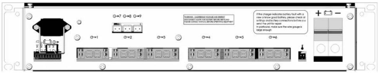

Bild 5 : Rückseite
1.1 Environmental specifications ....28
1.2 Electrical input and output specifications....28
1.2.1 Network input....28
1.2.2 Output....28
1.2.3 Specific features and technical specifications....29
1.2.4 Back-up duration and battery size....29
1.2.5 Authorized batteries....29
1.3 General internal view .... 30
1.4 Block diagram 30
2 Installation of the PSE 31
2.1 Mounting 31
2.2 Mains....31
2.3 Batteries 31
3 Connection 32
3.1 Connection overview....32
3.2 Connection specifications .... 32
4 Commissioning 32
5 Power supply operation.... 33
5.1 Alarms 33
5.2 Summary of available equipment....33
5.2.1 Battery test 33
5.2.2 Temperature compensation: 33
5.2.3 Battery low voltage protection: 33
5.2.4 Battery reverse connection protection....33
6 Maintenance 34
7 Fuse protections 34
8 Troubleshooting procedure 35
Appendix....36
Congratulations,
You have just acquired an emergency power supply by SLAT, and we thank you for your choice.
This manual includes instructions for the installation, commissioning and maintenance of this equipment.
In order for the equipment to work properly, we recommend that these instructions be followed very carefully.
Good installation.
Safety precautions
This equipment is designed to be connected to the 230 V public distribution network.
To avoid any risk of electric shock, all INTERVENTIONS must be carried out with DISCONNECTED MAINS SUPPLY.
An easily accessible isolating switch must therefore be installed outside of the cabinet. A bipolar isolation switch must be installed likewise in the batteries circuit.
Interventions with the equipment switched on are authorized only when it is impossible to switch the equipment off. The operation must only be performed by qualified personnel.
Standards, directives and protection of the environment and public health
This product is compliant with LV and EMC directives (immunity and emission).
It is compliant with standards:
• EN 60950-1 (2006) + A11 (2009) + A1 (2010) + A12 (2011) + A2 (2013) (TBTS class)
• EN 61000-6-1(2007), EN 61000-6-2 (2005), EN 61000-6-3 (2007), EN 61000-6-4 (2007) + A1 (2011)
• EN 55022 classe B (2007).
It is also compliant with the following trade standards:
- EN 54-4 (1997) + A1 (2002) + A2 (2006): Fire detection and fire alarm systems. Part 4: power supply equipment.
• EN 12101-10 class A (2005) : Smoke and heat control systems. Part 10: power supplies
The DoP numbers are: 0333-CPR-075381 (24V) and 0333-CPR-075383 (48V).
Year of CE marking: 2011.
SLAT is ISO 14001 certified since 2008.
SLAT manufactures all its products in accordance with RoHS and WEEE environmental directives.
SLAT recycles its products at the end of their service life through its recycling programme.

0333


Warranty
Our warranty is three years from the date of delivery (ex-works). It is strictly limited to reimbursement or replacement (at our discretion and without compensation of any sort) of parts recognised as faulty by our services, following return of the product to our premises at the buyer's expense. The replacement or repair of equipment is possible only on our premises. In order to allow our customers to benefit from the latest technical improvements, SLAT reserves the right to make all necessary modifications to its products. The battery is not included in the warranty.
GARANTIE
WARRANTY

ANS YEARS
1 Gerecal information General information
1.1 Environmental specifications
Operating temperature: -5 °C to +45 °C at 12 A.
Altitude : over 2000m, the max operating temperature decreases of 5°C every 1000 m.
Cooling operates transversally.
Storage temperature: -25 to +85 °C.
Operating relative humidity: 20 to 95 % without condensation,
Storage relative humidity: 10 to 95 %.
Environment class: 1 (according to EN 12101-10)
1.2 Electrical input and output specifications
1.2.1 Network input
- single-phase voltage: 220 V - 240 V.
- frequency: 50 Hz-60Hz.
- power consumption at full load: 380 W (PLN-24CH12) or 760 W (PRS-48CH12).
- maximum primary current @ 195 V: 2 A (SON 24V 12A MS150 RACK) or 4A (SON 48V 12A MS150 RACK).
- class I.
- neutral and earthing systems: TT, TN, IT.
- two pole circuit breaker (D curve) to be provided upstream.
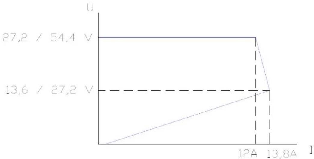
1.2.2 Output
- Rated voltage: 24 V (SON 24V 12A MS150 RACK) or 48V (SON 48V 12A MS150 RACK).
- Floating voltage set at half-load and at 25 °C: 27.2 V ±0.5 % or 54.4V +/-0.5%.
- 6 main outputs with a current of 40A maximum per output (protection see chapter 7)
- 3 auxiliary outputs with a current of 5A maximum per output. (protection see chapter 7)
- the maximum total current of the 9 outputs is 150A.
- the power supply can operate without load current: Imin = 0 A.
- Rated output current of rectifier : 12A
- Switching time: 0s
1.2.3 Specific features and technical specifications
If your amplifiers are not supplied by the same mains as the Power Supply Equipment, a failure of the mains of the amplifiers must generate an alarm to the voice alarm system.
In normal operating mode: the Power Supply Equipment recharges the batteries and maintains them when they are fully charged. The maximum current that can be provided to the user outputs is Imax a.
In back-up operating mode: the total operating current is provided by the batteries and may not exceed 'Imax b mains not present'.
Imax a : maximum available current which may be drawn continuously while charging the battery. Imax a = 12A - C/20 (C : battery capacity in Ah).
Imax b (mains present) : maximum available output current which may be drawn a short time, during which the battery may not be charged, but not discharged. Imax b (mains present) = 12 A
Imax b (mains not present) : maximum available current which may be drawn from the batteries when the mains supply is not available, 150A if the jumper is set on '75', or 100A if the jumper is set on '50' (see figure 1).
1.2.4 Back-up duration and battery size
To determine the battery size according to the required back-up duration of your power supply and interpret the battery code dates, consult our website: www.slat.fr
1.2.5 Authorized batteries
- If Imax b (mains not present) is greater than 100A, use batteries with a capacity of 86 to 225 Ah and set daughter board jumper on '75'.
- If Imax b (mains not present) is less than 100A, use batteries with a capacity of 65 to 225Ah, and set daughter board jumper on '50'.
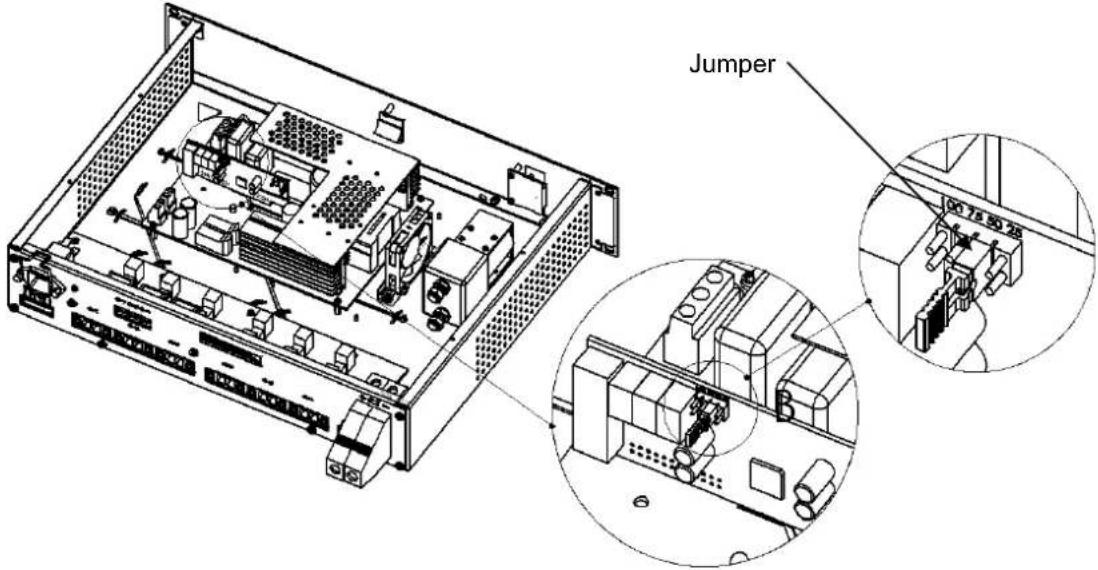
Figure 1 : Location of the jumper
The jumper is set on the '50' position as factory setting. Any other position of the jumper operates like '50' except the '75' position.
- Following batteries have been approved:
• Fiamm FG Series
- Yuasa NP Series
- Effekta BTL Series
• Powersonic GB Series
- Long GB Series
- Sun FT Series
- Enersys VE Series
- ABT TM Series.
If you would like to use another battery type, please let us approve them.
Check that the batteries are in conformity with the standards effective in the countries where they are used
1.3 General internal view
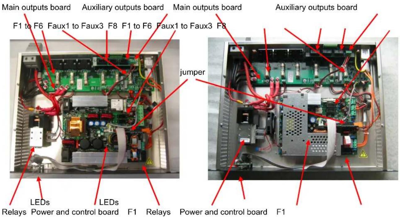
Figure 2 General internal view
1.4 Block diagram
![graph TD subgraph_Main_outputs_Board["Main outputs board"] A1["Output 9"] --> B1["Auxiliary outputs board"] A2["Output 8"] --> B1 A3["Output 7"] --> B1 B1 --> C1["Fout3"] B1 --> C2["Fout2"] B1 --> C3["Fout1"] end subgraph_Power_Control_Board["Power and control board"] D1["Output 6"] --> E1["Alarm ou…](/content/2026/03/525361/images/43c0c4e4170248c6b7636869df50cbaa18a8cfd48634100c7578648f22d7fa1b.jpg)
Figure 3 : Block diagram
It is advised to secure the battery with a fuse with low resistance. For its size, refer to chapter 7.
2 Installation of the PSE Installation of the PSE
2.1 Mounting
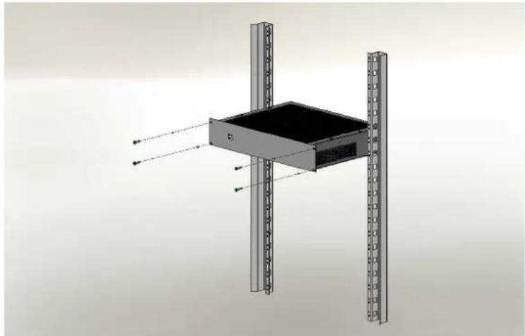
Figure 4 : Mounting the PSE
The charger has to be installed in a 19"rack that complies to Class 3k5 of EN60721-3-3:1995 +A2:1997 and IP30 of EN60529:1991+A1:2000.
2.2 Mains
Use a bipolar D curve circuit breaker (4A for 24V version and 6A for 48V version) to connect the power supply to the mains circuit.
2.3 Batteries
The battery temperature sensor must be placed as close to the battery as possible but doesn't need to be in contact with it. For example, it may be fixed on the battery cables by mean of the two tire wraps fitted.

Battery wiring instructions
Use a bipolar isolating switch (e.g. isolator or disconnecting switch) by connecting the batteries to the supply. An additional fuse is also recommended to protect this circuit.
In order to avoid any electrical damage, the cables connecting the batteries must imperatively match with the supply configuration (100 or 150A): maximum sheath temperature, cross section, allowed current, maximum voltage.
Operation :
The power supply takes a resistance measurement of the battery including connections every 4 hours.
The trigger threshold of the fault is 16mΩ ± 10% in 24V and 32mΩ ± 10% in 48V if the jumper is set on '75', and becomes 24mΩ ± 10% in 24V and 48mΩ ± 10% for 48V if the jumper is set on '50'.
Exceeding this threshold is signalled as a battery fault (see chapter 5) and means that the power supply with its associated battery will not have the required back-up duration in case of mains power cut.
To avoid initiating this fault, please note the following elements:
- Use authorized batteries (see chapter 1.2.5).
- Do not exceed the lengths of the table (see appendix page 34 and following)
- Ensure proper connections and crimpings.
- An additional battery fuse will add about 1 to 2 mΩ.
3 ConnectionConnection
3.1 Connection overview
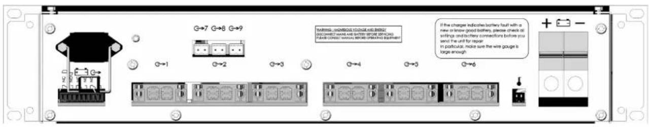
Figure 5 : Rear side view of PSE

Important: the openings provided in the cabinet must be kept free. Do not create additional openings because this can cause the device to malfunction and voids the warranty.
3.2 Connection specifications
- Mains: 2.5 mm2 .
- Battery: 16 to 50 mm 4 .
- Main outputs (outputs 1 to 6): 16 mm 2 .
- Auxiliary outputs (outputs 7 to 9): 2.5 mm 4 .
- Alarm reports (plug-in): 1.5 mm 4 .
4 Commissioning Commissioning
Before wiring, open the battery breaker and the mains circuit-breaker
After the electrical connections are made (mains, loads and batteries).
- Close the upstream mains circuit-breaker.
- Check the load output voltage.
- Close the battery breaker.
Your apparatus is in correct operation when the 3 LEDs on the front of the PSE are green.
If not, refer to chapter 8
5 Power supply operation Power supply operation
5.1 Alarms
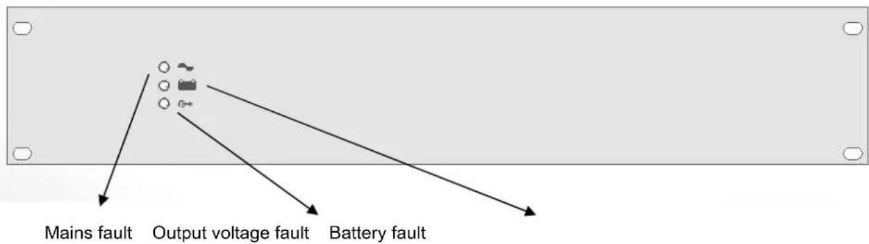
Figure 6 : Front side view of PSE
Mains fault (normal source): signalled on the front of the PSE by a yellow LED and available on dry contact with 5 sec delay (failsafe) for remote monitoring.
If the mains is not present or < 185 V +/-5% as long as the charger was switched off, <165V +/-5% if it was switched on.
If the mains fuse is blown or not present.
If the charger is faulty.
If the internal temperature is too high
Battery fault (back-up source): signalled on the front of the PSE by a yellow LED and available on dry contact (failsafe) for remote monitoring.
If the battery is not present (see chapter 5.2.1)
If the internal impedance is too high (see chapter 5.2.1)
If the battery voltage < 23,5 V ±3 %. resp. 47,0 V ±3 % mains present
Output voltage fault: signalled on the front of the PSE by a yellow LED and available on dry contact (failsafe) for remote monitoring.
If no voltage on one or more output. All the nine outputs are checked.
Each dry contact is a three pole SPDT switch (C-NC-NO), allowing 1A @ 24Vdc or 0,5A @ 120Vac.
5.2 Summary of available equipment
5.2.1 Battery test
The battery presence test is performed in the following manner: every 30 seconds for the first 20 minutes after commissioning and every 15 minutes after. As soon as a fault is detected, the test is performed every 30 seconds until 20 minutes after the fault disappears.
The impedance measurement test occurs every 4 hours if the mains is present on the power supply and if his current is < 12A. The impedance limit value is 16mΩ ± 10% in 24V and 32mΩ ± 10% in 48V if the jumper is set on '75', and becomes 24mΩ ± 10% in 24V and 48mΩ ± 10% for 48V if the jumper is set on '50' (see chapter 1.2.5).
5.2.2 Temperature compensation:
A battery voltage compensation system maintains the charge characteristics within the limits specified by the battery manufacturer across the entire operational temperature range.
5.2.3 Battery low voltage protection:
- The battery low voltage protection threshold is 21,6 V ±3% (SON 24V 12A MS150 RACK) or 43.2 V ±3% (SON 48V 12A MS150 RACK).
- The element causing the cut-out will be in the + position.
5.2.4 Battery reverse connection protection
- At start-up: the battery relays will not close
- During operation : the fuse F8 will blow out
6 Maintenance Maintenance
In order to ensure maximal and durable service, we strongly recommend that your product be maintained clean and ensure that it is installed in a dry and ventilated location. We shall in no case be liable for damages associated with improper use or incorrect maintenance of the equipment.

Replacing the original battery with a battery of incorrect type may result in an explosion hazard.
Used batteries must be disposed of in compliance with recycling requirements.
7 Fuse protections Fuse protections
| F1 mother board (mains):Rating – type – size – breaking capacity | 6.3 A T for 24V version8A T for 48V version5x201500 A breaking capacity |
| F8 mother boardRating – type – size | 12,5A T5x20 |
| F1 to F6 main outputs board (6 outputs) :rating - type – size | 32 A gG10x38 |
| Faux1 to Faux3 auxiliary outputs board (3 outputs):rating - type – size | 5A F5x20 |
| External battery fuse (not fitted with PSE) rating - type | [lbmax (mains not present)] AgG type |
8 Troubleshooting procedure Troubleshooting proced
The indicator light are not illuminated
- Check the mains voltage
- Check the primary fuse F1 on the power and control board
- Check that the flat ribbon cable is correctly connected
The output indicator light is yellow
- Check the output fuses F1 to F6
- Check the auxiliary fuses F1 to F3
The battery indicator light is yellow
- Check that the nominal battery voltage is ok with the sytem voltage
- Check the polarity connections of each battery and on the rack battery connector
- Check the battery connections and the battery fuse connections
- Check the voltage of each battery block (>1,9V / >5,7V / >10,8V)
- Check that the battery is approuved (see Pr 1.2.5)
- If the mains is present, check that the output current is < 12A
- The internal battery resistor may be too high: replace the battery
The mains indicator light is yellow
- Check the mains voltage
- Check the primary fuse F1 on the power and control board
- Check that cooling of the rack is sufficient and that the ambient temperature is < 45 ° C
For additional technical assistance, contact the SLAT hotline
For return requests, visit our website
or contact SLAT After-Sales Service to obtain an RMA (Return Material Authorisation) number.
Returns are not accepted without an RMA number.

The cross section and length values indicated in the next tables are given only for functional
use.
They have not been taken in account during the Low Voltage Directive certification according to EN60950-1.
| Longueur de la paire de câbles batterie / Länge des Batteriekabelpaars / Length of the battery cables pair (cm) | ||||||||||
| n.a. : non autorisé (voir §1.2.5) / nicht gestattet (siehe §1.2.5) / not allowed (see §1.2.5) | ||||||||||
| Tension / Spannung / Voltage -> | 24V | |||||||||
| Section / Durchschnitt / Section( mm2 ) -> 16 | 25 35 50 | |||||||||
| Jumper - position / Stelle / position -> 100 | A 150A | 100A | 150A | 100A | 150A | 100A | 150A | |||
| C20 | Brand | Typ | ||||||||
| 65,0 Ah | ABT | TM12-310W | 196 | n.a. 307 | n.a. | 430 | n.a. 614 | n.a. | ||
| 65,0 Ah | Effekta | BTL12-65 | 200 | n.a. 313 | n.a. | 438 | n.a. 625 | n.a. | ||
| 65,0 Ah | Fiamm | FG26505 | 422 | n.a. 660 | n.a. | 924 | n.a. 1319 | n.a. | ||
| 65,0 Ah | Fiamm | FG26507 | 422 | n.a. 660 | n.a. | 924 | n.a. 1319 | n.a. | ||
| 65,0 Ah | PowerSonic | PS12650GB | 84 | n.a. | 132 n.a. | 185 | n.a. 264 | n.a. | ||
| 65,0 Ah | Yuasa | NP65-12 | 244 | n.a. 382 | n.a. | 535 | n.a. 764 | n.a. | ||
| 68,0 Ah | Long | 6FM65G/B | 111 | n.a. 174 | n.a. | 243 | n.a. 347 | n.a. | ||
| 70,0 Ah | ABT | TM12-320W | 340 | n.a. 532 | n.a. | 745 | n.a. 1064 | n.a. | ||
| 70,0 Ah | Fiamm | FG27004 | 280 | n.a. 438 | n.a. | 613 | n.a. 875 | n.a. | ||
| 70,0 Ah | Fiamm | FG27007 | 413 | n.a. 646 | n.a. | 904 | n.a. 1292 | n.a. | ||
| 73,5 Ah | Long | 6FM70G/B | 200 | n.a. 313 | n.a. | 438 | n.a. 625 | n.a. | ||
| 75,0 Ah | ABT | TM12-350W | 347 | n.a. 542 | n.a. | 758 | n.a. 1083 | n.a. | ||
| 75,0 Ah | Effekta | BTL12-75 | 227 | n.a. 354 | n.a. | 496 | n.a. 708 | n.a. | ||
| 75,0 Ah | Enersys | 12VE75 | 283 | n.a. 442 | n.a. | 618 | n.a. 883 | n.a. | ||
| 75,0 Ah | PowerSonic | PS12750GB | 147 n.a. 229 n.a. 321 n.a. 458 n.a. | |||||||
| Longueur de la paire de câbles batterie / Länge des Batteriekabelpaars / Length of the battery cables pair (cm) | ||||||||||
| n.a. : non autorisé (voir §1.2.5) / nicht gestattet (siehe §1.2.5) / not allowed (see §1.2.5) | ||||||||||
| Tension / Spannung / Voltage -> | 24V | |||||||||
| Section / Durchschnitt / Section(mm2) -> 16 | 25 35 50 | |||||||||
| Jumper - position / Stelle / position -> 100A 150A | 100A | 150A | 100A | 150A | 100A | 150A | ||||
| C20 | Brand | Typ | ||||||||
| 78,0 Ah | Yuasa | NPL78-12IFR | 289 n.a. 451 n.a. 632 n.a. 903 n.a. | |||||||
| 80,0 Ah | Effekta | BTL12-80 | 244 n.a. 382 n.a. 535 n.a. 764 n.a. | |||||||
| 80,0 Ah | Fiamm | FG28009 | 431 n.a. 674 n.a. 943 n.a. 1347 | n.a. | ||||||
| 82,5 Ah | Sun | SB12-75FT | 289 n.a. 451 n.a. 632 n.a. 903 n.a. | |||||||
| 84,0 Ah | Long | 6FM80G/B | 200 n.a. 313 n.a. 438 n.a. 625 n.a. | |||||||
| 90,0 Ah | Effekta | BTL12-90 | 271 0 424 0 593 0 847 0 | |||||||
| 90,0 Ah | Enersys | 12VE90 | 329 0 514 76 719 107 1028 153 | |||||||
| 99,0 Ah | Sun | SB12-90FT | 333 53 521 83 729 117 1042 167 | |||||||
| 100,0 Ah | Effekta | BTL12-100 | 289 0 451 0 632 0 903 0 | |||||||
| 100,0 Ah | Fiamm | FG2A007 | 458 178 715 278 1001 389 1431 556 | |||||||
| 100,0 Ah | PowerSonic | PS121000GB | 298 0 465 0 651 0 931 56 | |||||||
| 100,0 Ah | Yuasa | NPL100-12 | 378 98 590 153 826 214 1181 306 | |||||||
| 105,0 Ah | Long | 6FM100G/B | 289 0 451 0 632 0 903 0 | |||||||
| 110,0 Ah | Sun | SB12-105FT | 351 71 549 111 768 156 1097 222 | |||||||
| 110,0 Ah | Sun | SB12-100HFT | 351 71 549 111 768 156 1097 222 | |||||||
| 120,0 Ah | Effekta | BTL12-120 | 378 98 590 153 826 214 1181 306 | |||||||
| 120,0 Ah | Fiamm | FG2C007 | 502 222 785 347 1099 486 1569 694 | |||||||
| 121,0 Ah | Long | 6FM115G/B | 289 0 451 0 632 0 903 0 | |||||||
| 126,0 Ah | Long | 6FM120G/B | 378 98 590 153 826 214 1181 306 | |||||||
| 137,4 Ah | Sun | SB12-125FT | 449 169 701 264 982 369 1403 528 | |||||||
| 140,0 Ah | Enersys | 6VE140 | 479 199 749 311 1048 436 1497 622 | |||||||
| 150,0 Ah | Effekta | BTL12-150 | 378 98 590 153 826 214 1181 306 | |||||||
| 150,0 Ah | Fiamm | FG2F009 | 547 267 854 417 1196 583 1708 833 | |||||||
| 165,0 Ah | Sun | SB12-150FT | 467 187 729 292 1021 408 1458 583 | |||||||
| 180,0 Ah | Enersys | 6VE180 | 518 238 810 372 1134 521 1619 744 | |||||||
| 180,4 Ah | Sun | SB12-180FT | 476 196 743 306 1040 428 1486 611 | |||||||
| 200,0 Ah | Effekta | BTL12-200 | 378 98 590 153 826 214 1181 306 | |||||||
| 200,0 Ah | Fiamm | FG2M009 | 591 311 924 486 1293 681 1847 972 | |||||||
| 200,0 Ah | Yuasa | NPL200-6 | 502 222 785 347 1099 486 1569 694 | |||||||
| 210,0 Ah | Long | 6FM200G/B | 467 187 729 292 1021 408 1458 583 | |||||||
| 225,0 Ah | Enersys | 2VE225 | 525 245 821 383 1149 537 1642 767 | |||||||
| Longueur de la paire de câbles batterie / Länge des Batteriekabelpaars / Length of the battery cables pair (cm) | ||||||||||
| n.a. : non autorisé (voir §1.2.5) / nicht gestattet (siehe §1.2.5) / not allowed (see §1.2.5) | ||||||||||
| Tension / Spannung / Voltage -> | 48V | |||||||||
| Section / Durchschnitt / Section(mm2) -> | 16 25 35 50 | |||||||||
| Jumper - position / Stelle / position -> | 100A | 150A | 100A | 150A | 100A | 150A | 100A | 150A | ||
| C20 | Brand | Typ | ||||||||
| 65,0 Ah ABT | TM12-310W | 460 | n.a. 71 | 8 n.a. | 1005 | n.a. 14 | 36 | n.a. | ||
| 65,0 Ah Effekta | BTL12-65 | 467 | n.a. 72 | 9 n.a. | 1021 | n.a. 14 | 58 | n.a. | ||
| 65,0 Ah Fiamm | FG26505 | 911 | n.a. 14 | 24 | n.a. | 1993 | n.a. 284 | 7 | n.a. | |
| 65,0 Ah Fiamm | FG26507 | 911 | n.a. 14 | 24 | n.a. | 1993 | n.a. 284 | 7 | n.a. | |
| 65,0 Ah PowerSonic | PS12650GB | 236 | n.a. | 368 | n.a. | 515 | n.a. | 736 | n.a. | |
| 65,0 Ah Yuasa | NP65-12 | 556 | n.a. 86 | 8 n.a. | 1215 | n.a. 17 | 36 | n.a. | ||
| 68,0 Ah Long | 6FM65G/B | 289 | n.a. | 451 | n.a. | 632 | n.a. | 903 | n.a. | |
| 70,0 Ah ABT | TM12-320W | 748 | n.a. 11 | 68 | n.a. | 1635 | n.a. 233 | 6 | n.a. | |
| 70,0 Ah Fiamm | FG27004 | 627 | n.a. 97 | 9 n.a. | 1371 | n.a. 19 | 58 | n.a. | ||
| 70,0 Ah Fiamm | FG27007 | 893 | n.a. 13 | 96 | n.a. | 1954 | n.a. 279 | 2 | n.a. | |
| 73,5 Ah Long | 6FM70G/B | 467 | n.a. 72 | 9 n.a. | 1021 | n.a. 14 | 58 | n.a. | ||
| 75,0 Ah ABT | TM12-350W | 760 | n.a. 11 | 88 | n.a. | 1663 | n.a. 237 | 5 | n.a. | |
| 75,0 Ah Effekta | BTL12-75 | 520 | n.a. 81 | 3 n.a. | 1138 | n.a. 16 | 25 | n.a. | ||
| 75,0 Ah Enersys | 12VE75 | 632 | n.a. 98 | 8 n.a. | 1383 | n.a. 19 | 75 | n.a. | ||
| 75,0 Ah PowerSonic | PS12750GB | 360 | n.a. 56 | 3 n.a. | 788 | n.a. | 1125 | n.a. | ||
| 78,0 Ah Yuasa | NPL78-12IFR | 644 | n.a. 10 | 07 | n.a. | 1410 | n.a. 2014 | n.a. | ||
| 80,0 Ah Effekta | BTL12-80 | 556 | n.a. 86 | 8 n.a. | 1215 | n.a. 17 | 36 | n.a. | ||
| 80,0 Ah Fiamm | FG28009 | 929 | n.a. 14 | 51 | n.a. | 2032 | n.a. 290 | 3 | n.a. | |
| 82,5 Ah Sun | SB12-75FT | 644 | n.a. 10 | 07 | n.a. | 1410 | n.a. 2014 | n.a. | ||
| 84,0 Ah Long | 6FM80G/B | 467 | n.a. 72 | 9 n.a. | 1021 | n.a. 14 | 58 | n.a. | ||
| 90,0 Ah Effekta | BTL12-90 | 609 | 0 | 951 | 76 | 1332 | 107 | 1903 | 153 | |
| 90,0 Ah Enersys | 12VE90 | 724 | 164 | 11 | 32 | 1585 | 360 | 226 | 514 | |
| 99,0 Ah Sun | SB12-90FT | 733 | 173 | 11 | 46 | 271 | 1604 | 379 | 229 | |
| 100,0 Ah Effekta | BTL12-100 | 644 | 84 | 10 | 07 | 132 | 1410 | 185 | 2014 | |
| 100,0 Ah Fiamm | FG2A007 | 982 | 422 | 15 | 35 | 660 | 2149 | 924 | 3069 | |
| 100,0 Ah PowerSonic | PS121000GB | 662 | 102 | 10 | 35 | 160 | 1449 | 224 | 2069 | |
| 100,0 Ah Yuasa | NPL100-12 | 822 | 262 | 12 | 85 | 410 | 1799 | 574 | 2569 | |
| 105,0 Ah Long | 6FM100G/B | 644 | 84 | 10 | 07 | 132 | 1410 | 185 | 2014 | |
| 110,0 Ah Sun | SB12-105FT | 769 | 209 | 12 | 01 | 326 | 1682 | 457 | 2403 | |
| 110,0 Ah Sun | SB12-100HFT | 769 | 209 | 12 | 01 | 326 | 1682 | 457 | 2403 | |
| 120,0 Ah Effekta | BTL12-120 | 822 | 262 | 12 | 85 | 410 | 1799 | 574 | 2569 | |
| 120,0 Ah Fiamm | FG2C007 | 1071 | 511 | 16 | 74 | 799 | 2343 | 1118 | 3347 | |
| 121,0 Ah Long | 6FM115G/B | 644 | 84 | 10 | 07 | 132 | 1410 | 185 | 2014 | |
| 126,0 Ah Long | 6FM120G/B | 822 | 262 | 12 | 85 | 410 | 1799 | 574 | 2569 | |
| 130,0 Ah Yuasa | NPL130-6IFR | 644 | 84 | 10 | 07 | 132 | 1410 | 185 | 2014 | |
| C20 | Brand | Typ | ||||||||
| 137,4 Ah Sun | SB12-125FT | 964 | 404 15 | 07 | 632 | 2110 885 301 | 4 | 1264 | ||
| 140,0 Ah Enersys | 6VE140 | 1025 | 465 | 1601 | 726 | 2242 1017 | 3203 | 1453 | ||
| 150,0 Ah Effekta | BTL12-150 | 822 | 262 12 | 85 | 410 | 1799 574 256 | 9 | 819 | ||
| 150,0 Ah Fiamm | FG2F009 | 1160 | 600 | 1813 | 938 | 2538 1313 | 3625 | 1875 | ||
| 165,0 Ah Sun | SB12-150FT | 1000 | 440 | 1563 | 688 | 2188 963 312 | 5 | 1375 | ||
| 180,0 Ah Enersys | 6VE180 | 1103 | 543 | 1724 | 849 | 2413 1188 | 3447 | 1697 | ||
| 180,4 Ah Sun | SB12-180FT | 1018 | 458 | 1590 | 715 | 2226 1001 | 3181 | 1431 | ||
| 200,0 Ah Effekta | BTL12-200 | 822 | 262 12 | 85 | 410 | 1799 574 256 | 9 | 819 | ||
| 200,0 Ah Fiamm | FG2M009 | 1249 | 689 | 1951 | 1076 | 2732 1507 | 3903 | 2153 | ||
| 200,0 Ah Yuasa | NPL200-6 | 1071 | 511 | 1674 | 799 | 2343 1118 | 3347 | 1597 | ||
| 210,0 Ah Long | 6FM200G/B | 1000 | 440 | 1563 | 688 | 2188 963 312 | 5 | 1375 | ||
| 225,0 Ah Enersys | 2VE225 | 1117 | 557 | 1746 | 871 | 2444 1219 | 3492 | 1742 | ||
SLAT
11, Rue Jean Elysée Dupuy BP66 69543 CHAMPAGNE AU MONT D'OR
Cedex
France
- 3 RACCORDEMENTRACCORDEMENT
- 3.1 PLAN DE RACCORDEMENT
- 2 INSTALLATION OF THE PSE 31
- 3 CONNECTION 32
- 4 COMMISSIONING 32
- 5 POWER SUPPLY OPERATION.... 33
- 6 MAINTENANCE 34
- 7 FUSE PROTECTIONS 34
- 8 TROUBLESHOOTING PROCEDURE 35
- APPENDIX....36
- CONGRATULATIONS
- GOOD INSTALLATION
- SAFETY PRECAUTIONS
- STANDARDS, DIRECTIVES AND PROTECTION OF THE ENVIRONMENT AND PUBLIC HEALTH
- WARRANTY
- 1 GERECAL INFORMATION GENERAL INFORMATION
- 1.1 ENVIRONMENTAL SPECIFICATIONS
- 1.2 ELECTRICAL INPUT AND OUTPUT SPECIFICATIONS
- 1.2.1 NETWORK INPUT
- 1.2.2 OUTPUT
- 1.2.3 SPECIFIC FEATURES AND TECHNICAL SPECIFICATIONS
- 1.2.4 BACK-UP DURATION AND BATTERY SIZE
- 1.2.5 AUTHORIZED BATTERIES
- 1.3 GENERAL INTERNAL VIEW
- 1.4 BLOCK DIAGRAM
- 2 INSTALLATION OF THE PSE INSTALLATION OF THE PSE
- 2.1 MOUNTING
- 2.2 MAINS
- 2.3 BATTERIES
- BATTERY WIRING INSTRUCTIONS
- OPERATION
- 3 CONNECTIONCONNECTION
- 3.1 CONNECTION OVERVIEW
- 3.2 CONNECTION SPECIFICATIONS
- 4 COMMISSIONING COMMISSIONING
- 5 POWER SUPPLY OPERATION POWER SUPPLY OPERATION
- 5.1 ALARMS
- 5.2 SUMMARY OF AVAILABLE EQUIPMENT
- 5.2.1 BATTERY TEST
- 5.2.2 TEMPERATURE COMPENSATION
- 5.2.3 BATTERY LOW VOLTAGE PROTECTION
- 5.2.4 BATTERY REVERSE CONNECTION PROTECTION
- 6 MAINTENANCE MAINTENANCE
- 8 TROUBLESHOOTING PROCEDURE TROUBLESHOOTING PROCED
- THE INDICATOR LIGHT ARE NOT ILLUMINATED
- THE OUTPUT INDICATOR LIGHT IS YELLOW
- THE BATTERY INDICATOR LIGHT IS YELLOW
- THE MAINS INDICATOR LIGHT IS YELLOW
- SLAT
Brand : Proel
Model : SON 24V 12A MS150 RACK
Category : Power Supply