
POC615 - Laptop Advantech - Free user manual and instructions
Find the device manual for free POC615 Advantech in PDF.
| Brand | Advantech |
| Model | POC615 |
| Product type | Medical laptop |
| Intended use | Medical professional (not suitable for flammable anesthetic mixtures) |
| Power supply | Class I AC adapter, 100-240 VAC |
| Battery | Removable lithium-ion, warranty 1 year or 300 cycles at 70% capacity |
| Display | 12.1 inches (according to reference POC-615-12) |
| Mounting | VESA compatible (installation by trained personnel) |
| Cleaning | Damp cloth, no liquid or aerosol detergents, no phenol |
| Safety | Mandatory grounding on "Hospital only" outlet |
| Standards | IEC 60601-1 (electromedical devices), IEC 60601-1-2 (EMC) |
| Operating temperature | Approximately 0°C to 40°C (estimate) |
| Storage temperature | Approximately -20°C to 60°C (estimate based on instructions) |
| Weight | Approximately 3.5 kg (estimate) |
| Dimensions | Approximately 300 x 200 x 50 mm (estimate) |
| Repairability | By qualified personnel only (no user-serviceable parts) |
| Supplied accessories | Power cord with grounding plug, AC adapter |
| Compliance | CE, medical standards (IEC 60601-1) |
Frequently Asked Questions - POC615 Advantech
User questions about POC615 Advantech
0 question about this device. Answer the ones you know or ask your own.
Ask a new question about this device
Download the instructions for your Laptop in PDF format for free! Find your manual POC615 - Advantech and take your electronic device back in hand. On this page are published all the documents necessary for the use of your device. POC615 by Advantech.
USER MANUAL POC615 Advantech
11th Generation Intel Processor
Instructions for the User
The document combines text and illustrations, providing a comprehensive overview of the system. The information is presented as a sequential steps of actions, allowing the user to learn directly how to use the device.
The text provides explanations and instructs the user step-by-step in the practical use of the product, with short, clear instructions in an easy-to-follow sequence.
Definitions
Warning! A WARNING statement provides important information about a potentially hazardous situation which, if not avoided, could result in death or serious injury.
Caution! A CAUTION statement provides important information about a potentially hazardous situation which, if not avoided, may result in minor or moderate injury to the user or patient or in damage to the equipment or other property.
Note! A NOTE provides additional information intended to avoid inconveniences during operation.
Safety Instructions
- Strictly follow these Instructions for Use, please read these safety instructions carefully.
- Please keep this User Manual for later reference; any use of the product requires full understanding and strict observation of all portions of these instructions. Observe all WARNINGs and CAUTIONS as rendered throughout this manual and on labels on the equipment.
- Repair of the device may also only be carried out by trained service personnel. Advantech recommends that a service contract be obtained with Advantech Service and that all repairs also be carried out by them. Otherwise the correct functioning of the device may be compromised.
Warning! Because of the danger of electric shock, never remove the cover of a device while it is in operation or connected to a power outlet.

- If one of the following situations arises, get the equipment checked by service personnel:
The power cord or plug is damaged.
Liquid has penetrated into the equipment.
The equipment has been exposed to moisture.
The equipment does not work well, or you cannot get it to work according to the user's manual.
The equipment has been dropped and damaged.
The equipment has obvious signs of breakage.
- Disconnect this equipment from any AC outlet before cleaning. Use a damp cloth. Do not use liquid or spray detergents for cleaning and keep this equipment away from humidity.
Caution!
To avoid short-circuiting and otherwise damaging the device, do not allow fluids to come in contact with the device. If fluids are accidentally spilled on the equipment, remove the affected unit from service as soon as possible and contact the service personnel to verify that patient safety is not compromised.
- Put this equipment on a reliable surface during installation. Dropping it or letting it fall may cause damage. For plug-in equipment, the power outlet socket must be located near the equipment and must be easily accessible.

Caution! To prevent overheating, do not cover the openings and place the device in direct sunlight or near radiant heaters.
- Make sure the voltage of the power source is correct before connecting the equipment to the power outlet. Position the power cord so that people cannot step on it. Do not place anything over the power cord. If the equipment is not used for a long time, disconnect it from the power source to avoid damage by transient over voltage.
Caution! Do not leave this equipment in an uncontrolled environment where the storage temperature is below 0°C (0°F) or above 50°C (122°F) . This may damage the equipment.
- If your computer is losing dramatic time or the BIOS configuration reset to default, the battery has no power.
Caution! Do not replace battery yourself. Please contact a qualified technician or your retailer.
The computer is provided with a battery- powered, real-time clock circuit. There is a danger of explosion if battery is incorrectly replaced. Replace only with BR2032 or equivalent type recommended by the manufacturer.
Discard used batteries according to the manufacturer's instructions.
Caution! The battery charging indicator is not included with this device. It will be added to the finished system assembly and be shown with the completed system.

-
Improper installation of VESA mounting can result in serious personal injury! VESA mount installation should be operated by professional technician, please contact the service technician or your retailer if you need this service. The detail operating procedure is specified in Chapter4.
-
CLASSIFICATION:
1). Class I internal powered
2). No applied part
3). Continuous Operation
4). Not AP or APG category
Warning! This device is not suitable for use in the presence of flammable anesthetic mixture with air, oxygen, nitrous oxide, or for life support system.

- Environmental protection: follow national requirements to dispose of unit.
- Maintenance: to properly maintain and clean the surfaces, use only the approved products or clean with a dry applicator.
Caution! When servicing the device, always use replacement parts that are qualified to Advantech standards. Advantech Medical cannot warrant or endorse the safe performance of third-party replacement parts for use with our medical device.
-
Make sure the user not to contact SIP/SOPs and the patient at the same time.
-
When networking with electrical devices, the operator is responsible for ensuring that the resulting system meets the requirements set forth by the following standards:
EN 60601-1 (IEC 60601-1) Medical electrical equipment
Part 1: General requirements for safety
- EN 60601-1-2 (IEC 60601-1-2) Medical electrical equipment
Part 1-2: General requirements for safety
Collateral standard: Electromagnetic compatibility; Requirements and tests
- Accessory equipment connected to analog and digital interfaces must be in compliance with the respective nationally harmonized IEC standards (i.e. IEC 60950 for data processing equipment, IEC 60065 for video equipment, IEC 61010-1 for laboratory equipment, and IEC 60601-1 for medical equipment.)

MEDICAL-GENERAL MEDICAL EQUIPMENT
WITH RESPECT TO ELECTRICAL SHOCK, FIRE AND MECHANICAL
HAZARDS ONLY IN ACCORDANCE WITH ANSI/AAMI ES60601-1
(2005 and Amendment 1) CAN/CSA-C22.2 NO.60601-1(2014)
Furthermore all configurations shall comply with the system standard IEC 60601-1. Anyone who connects additional equipment to the signal input part or signal output part is configuring a medical system, and is therefore, responsible that the system complies with the requirements of the system standard IEC 60601-1. The unit is for exclusive interconnection with IEC 60601-1 certified equipment in the patient environment and IEC 60XXX certified equipment outside of the patient environment. If in doubt, consult the technical services department or your local representative.
Caution!
Use suitable mounting apparatus to avoid risk of injury. it shall be mounted by trained and authorized personnel on adequate allowances for quality of materials used to make the connection
- Grounding reliability can only be achieved when the equipment is connected to an equivalent receptacle marked "Hospital Only" or "Hospital Grade".
- Use a power cord that matches the voltage of the power outlet, which has been approved and complies with the safety standard of your particular country.
Note!
Environmental protection
Follow national requirements to dispose of unit.

- WARNING - Do not modify this equipment without authorization of the manufacturer.
- WARNING - To avoid risk of electric shock, this equipment must only be connected to a supply mains with protective earth.
- Remove the power cord to fully turn off the device.
- Only use the power cord with following specification: 18AWG min., type SJT, UL/CSA listed, length: 1.8m , hospital grade if for USA/Canada market
- Installation is only to be carried out by manufacture authorized and trained personnel
- Device is intended to be used as SIP/SOP facing downward
Explanation of Graphical Symbols

IEC 60878 and ISO 3864-B.3.6: Warning: dangerous voltage

ISO 7000-0434: Caution, consult ACCOMPANYING DOCUMENTS.

ISO 7000-1641: Follow operating instructions or consult instructions for use.

IEC 60417-5009:STAND-BY.

IEC 60417-5032: Alternating Current

IEC 60417-5031: Direct Current

IEC 60417-5021: Equipotentiality.

ISO 7010-M002: Follow instructions for use
Disposing of Old Products
Within the European Union

EU-wide legislation, as implemented in each Member State, requires that waste electrical and electronic products carrying the mark (left) must be disposed of separately from normal household waste. This includes monitors and electrical accessories, such as signal cables or power cords. When you need to dispose of your display products, please follow the guidance of your local authority, or ask the shop where you purchased the product, or if applicable, follow any agreements made between yourself.
The mark on electrical and electronic products only applies to the current European Union Member States.
FCC Class B
This equipment has been tested and found to comply with the limits for a Class B digital device, pursuant to Part 15 of the FCC Rules.
These limits are designed to provide reasonable protection against harmful interference when the equipment is operated in a residential environment. This equipment generates uses and can radiate radio frequency energy. If not installed and used in accordance with this user's manual, it may cause harmful interference to radio communications.
Note that even when this equipment is installed and used in accordance with this user's manual, there is still no guarantee that interference will not occur. If this equipment is believed to be causing harmful interference to radio or television reception, this can be determined by turning the equipment on and off. If interference is occurring, the user is encouraged to try to correct the interference by one or more of the following measures:
Reorient or relocate the receiving antenna
Increase the separation between the equipment and the receiver
Connect the equipment to a power outlet on a circuit different from that to which the receiver is connected.
■ Consult the dealer or an experienced radio/TV technician for help
Warning!
Any changes or modifications made to the equipment which are not expressly approved by the relevant standards authority could void your authority to operate the equipment.
Warning!
This device complies with Part 15 of the FCC Rules. Operation is subject to the following two conditions:

(1) this device may not cause harmful interference, and
(2) this device must accept any interference received, including interference that may cause undesired operation.
Avertissement!
Before installing your Point of Care Terminal, ensure that the following materials have been received:
POC-615-12 SERIES Point-of-Care Terminal
Mounting kits and packet of screws.
VESA mounting note x1
China RoHs note x1
Warning! No user serviceable parts inside, refer servicing to qualified personnel. Only the accessories indicated on the list of accessories above have been tested and approved to be used with the device. Accordingly it is strongly recommended that only these accessories be used in conjunction with the specific device. Otherwise the correct functioning of the device may be compromised.
Avertissement!
Additional Information and Assistance
Contact your distributor, sales representative, or Advantech's customer service center for technical support if you need additional assistance. Please have the following information ready before you call:
Product name and serial number
Description of your peripheral attachments
Description of your software (operating system, version, application software, etc.)
A complete description of the problem
The exact wording of any error messages
This equipment is a source of electromagnetic waves. Before use please, make sure that there are not EMI sensitive devices in its surrounding which may malfunction therefore.
Environmental protection
Follow national requirements to dispose of unit.
Manufacturer
Advantech Co., Ltd.
No.1, Alley 20, Lane 26, Rueiguang Road Neihu District, Taipei,
Taiwan 114, R.O.C.
TEL: (02) 2792-7818
Distributed in Europe by:
Advantech Service IoT GmbH
Industriestraße 15
82110 Germering
Germany
Phone: +49 (0) 89 41 11 91-0
Fax: +49 (0) 89 41 11 91-900
Email: contact@advantech.de
URL: http://advantech-service-iot.eu
Visit the Advantech websites at www.advantech.com or www.advantech.com.tw if you need more information.
Contents
Chapter 1 General Information
1.1 Introduction 2
1.2 Specifications 2
Table 1.1: Specifications 2
1.3 Dimensions 3
Figure 1.1 Dimensions of the POC-615-12 series 4
Figure 1.2 Dimensions of the POC-615-12 series with smart card reader 4
Figure 1.3 Dimensions of the POC-615-12 series with RFID & camera. 5
Figure 1.4 VESA mounting of the POC-615-12 series 5
Figure 1.5 POC-615-12 series front panel.. 6
1.4 Optional Modules 6
1.4.1 Cleaning and Disinfecting 6
1.5 Operating Principle 7
1.6 Intended User Profile 8
Chapter 2 System Setup. 9
2.1 A Quick Tour of the POC-615-12 Series 10
2.1.1 Front View. 10
Figure 2.1 Front view of the point-of-care terminal 10
2.1.2 Rear View 10
Figure 2.2 Rear view of the point of care terminal 10
Figure 2.3 Rear view of multi I/O ports (AC-in model) 11
2.2 Installation Procedures 11
2.2.1 Connecting the Power Cord 11
Figure 2.4 Connecting the power cord. 11
2.2.2 Connecting the DCIN 12
2.2.3 Connecting the Ground Pin 12
Figure 2.5 POC-615-12 SERIES Equipotential Terminal Pin .... 12
Figure 2.6 Grounding cable with connector 13
2.3 Running the BIOS Setup Program 13
2.4 Installing System Software 13
2.5 Installing the Drivers 14
2.6 Troubleshooting 14
2.6.1 POC Not Powering ON 14
2.6.2 Adapter Power LED OFF. 15
2.6.3 POC System Powers On but Not Booting Windows 15
2.6.4 AC Powers and All Indicator ON, but System Doesn't Power On... 15
2.6.5 No Charge 15
2.7 EMC Declaration 16
Chapter 3 Operation and Safety 21
3.1 General Safety Guide 22
3.2Thermals 22
3.3 Disconnect the Power 23
3.4 Proper Handling 24
3.5 BatteryWarnings 24
3.6 Battery Safety Instruction 25
3.7 Emergency Scenarios 29
3.8 Battery Storage and Transportation 30
3.9 Battery Disposing 31
Chapter 4 Installing VESA Mount. 33
4.1 Installing the VESA Mounting 34
Figure 4.1 VESA mounting 34
Chapter 5 Driver Installation 35
5.1 Driver Installation 36
Table 5.1: Driver installation sequence 36
Chapter 6 PCM-8725 Connector Map. 37
6.1 POC System Uses PCM-8725 PCBA 38
Chapter 7 PCM-8725 Jumper Settings. 41
7.1 PCM-8725 Jumper Settings 42
Table 7.1: Jumper settings 42
Table 7.2: CN3 ME manufacturing mode 43
Table 7.3: CN5 clear CMOS. 43
Table 7.4: CN6 (not installed) clear ME 43
Table 7.5: CN8 system reset. 43
Table 7.6: CN13 LVDS voltage setup 44
Table 7.7: CN40 power button (reserved, internal test only). 44
Table 7.8: PCN4 power debug (reserved). 44
Table 7.9: SW1 board setup. 44
Table 7.10:Board configurations 45
Table 7.11:SW1 pin 4 speaker functions.. 45
Table 7.12:SW4 panel resolution/type setup.. 45
Table 7.13:SW4 Pins.. 45
Table 7.14:5 V LVDS panel. 46
Table 7.15:SW1 +SW2 pins 46
Chapter 8 Front Bezel Button. 47
8.1 Introduction 48
Chapter 9 Advanced BIOS Function 49
9.1 Advanced BIOS Function 50
Chapter 1
General Information
1.1 Introduction
The POC-615-12 SERIES is a multimedia Intel® Core™ i7 or i5 or Celeron processor series designed for mobile computing as a Point-of-Care terminal (POC.) It is a PC-based system with 15.6" wide screen TFT LCD display, HDMI and dual LAN. It has one COM ports, quad USB 2.0 ports and a 24-bit stereo audio controller. With an optional 2.5" SSD, the POC-615-12 SERIES is a user-friendly computer. For system integrators, this highly integrated multimedia system lets you easily build a Point-of-Care Terminal into your applications. The POC-615-12 SERIES makes it an ideal and safe point-of-care solution for patients and hospital practitioners. The POC-615-12 SERIES is specially designed to resist spills and water damage, and ensures dust resistance with its protected LCD and sealed ports. The POC-615-12 SERIES is a reliable solution to your application's processing requirements.
Intended use - The POC-615-12 SERIES is intended to serve as a Point-of-Care terminal (POC) for integration with hospital systems. POC-615-12 SERIES is designed for general purpose medical computing in the hospital environment, for data collection and for dis- playing information. It should not be used as a life-support system.
The latest version of this user manual is available for download from http://support.advantech.com.tw/support/
1.2 Specifications
Table 1.1: Specifications
| Computing System | CPU | Intel® Core™ i7-1185G7E (12M cache, up to 4.40 GHz)Intel® Core™ i5-1145G7E (8M cache, up to 4.10 GHz) |
| Memory 8GB DDR4 (supports up to 64GB DDR4 SODIMM) | ||
| Graphics Controller Intel® Iris® Xe Graphics | ||
| Display | Size 15.6 inch | |
| Type | 10-point multi touch P-CAP (clear glass); optional AG/AR support upon request | |
| Max. Resolution 1920 x 1080 (H x V) | ||
| Max. Colors 16.7 M colors (6-bits + A-FRC) | ||
| Pixel Pitch (um) 247.5 x 247.5 | ||
| Viewing Angle | 178/178° | |
| Luminance | 250 cd/m2 | |
| Backlight | LED | |
| LCD MTBF | 30,000 Hours | |
| Contrast Ratio | 1000 : 1 | |
| Expansion Slot | Mini PCIe | 1 (full size) |
| M.2 2230 | 1 (for Wi-Fi/Bluetooth module) | |
| PCIe x4** | 1 (max card length: 167.65 mm/6.6 in). | |
| I/O Ports | USB 3.2 Gen 2 (Type A) | 4 |
| USB 3.2 Gen 2 (Type C) | 1 (with display function) | |
| HDMI | 1 | |
| LAN Isolation, 1.5KV | 2 | |
| COM (RS232) 1.5KV | 1 | |
| Power Input | DC | 19 V, max. 150 W |
Table 1.1: Specifications
| Certification | Medical CE, FCC (IEC 60601-1-2, 4th edition)EN 60601-1 complianceUL 60601-1 | |
| Environment | Temperature | Operating: 0° ~ 35°C,Transport/storage: 0° ~ 50°C |
| Humidity | Operating: 10% ~ 90% @40°C non-condensed,Transport/storage: 5% ~ 90% @40°C non-condensed | |
| Shock Resistance 20G peak acceleration (11ms duration) | ||
| Pressure | 700-1013 hPa (operation)70-106 kPa (storage)70-106 kPa (transportation) | |
| Physical Characteris-tics | Dimensions(W x D x H) | 406 x 274 x 61 mm (15.98 x 10.79 x 2.4 in) |
| Weight (Bare system) | 4.89 kg/10.78 lb | |
| VESA Mount 100 x 100, 75 x 75 mm | ||
| Other Func-tions | Internal Speaker 2 x 2 W | |
| Internal TPM 2.0 (default via fTPM -firmware TPM) | ||
| Optional Configuration | Operating System | Windows 10 IoT Ent (64-bits only),Linux (support by request) |
| Memory Up to 64GB DDR4 SODIMM | ||
| Storage | NVME SSD 128G/ 256G/ 512GB PCIe interface or 128G/256G/ 512G/ 1TB 2.5" SATA SSD available | |
| WLAN Intel® Wi-Fi 6E AX210 or Intel Wireless-AC9260 | ||
| Bluetooth 5.3 / 5.1 | ||
| RFID | RFIDEAS KT-805N64KU(The Pico integrated card reader is a dual-band card reader capable of reading both 125 kHz and 13.56 MHz credentials.) | |
| Smart Card Reader | Smart card | |
| Backup Battery | Internal backup battery, POC-BAT-101-6A, lithium-ion 8400 mAh 10.8 V 90.72W 3S3P). | |
| Camera | 5MP, auto focus | |
| Touch Panel | 15.6", clear glass, AR/AG (request by project) | |
1.3 Dimensions
Dimensions: 405 × 274 × 60 mm (Unit: mm)
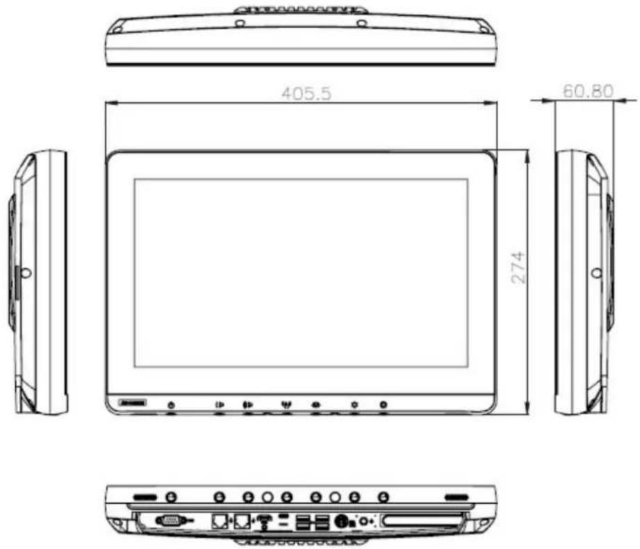
Figure 1.1 Dimensions of the POC-615-12 series
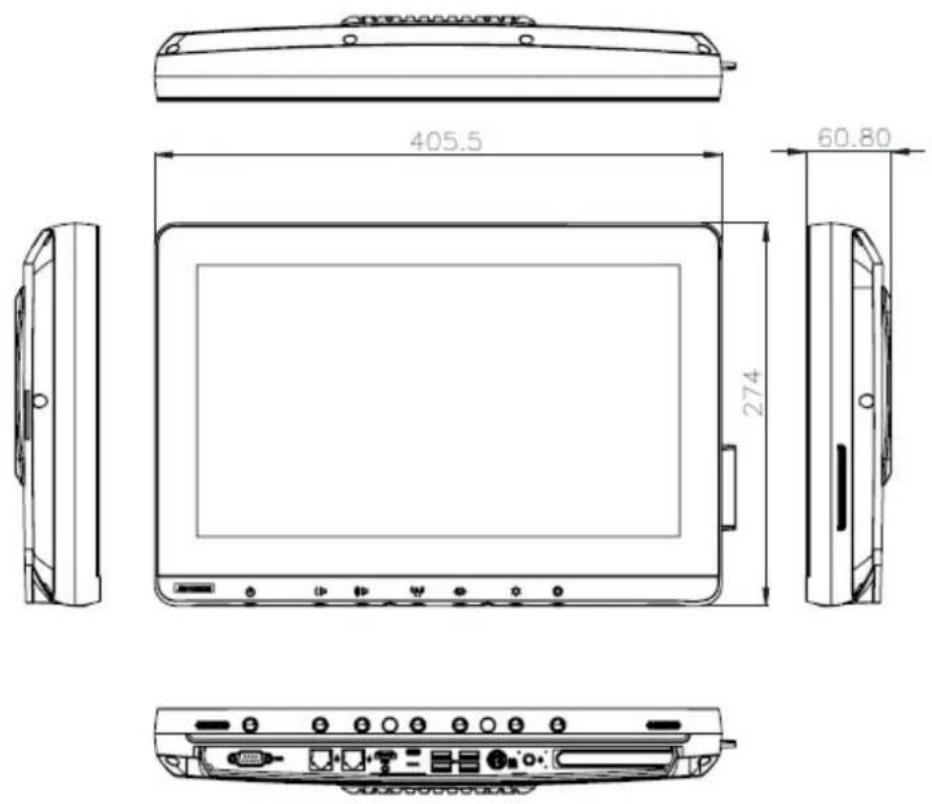
Figure 1.2 Dimensions of the POC-615-12 series with smart card reader
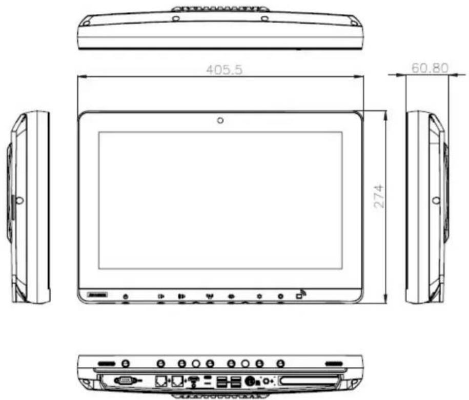
Figure 1.3 Dimensions of the POC-615-12 series with RFID & camera
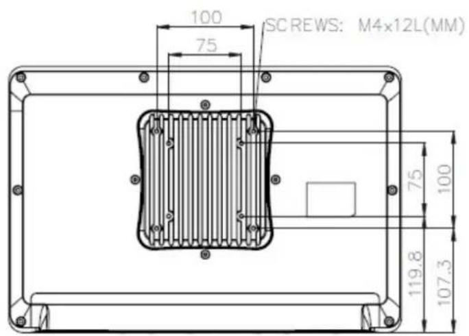
Figure 1.4 VESA mounting of the POC-615-12 series
VESA mounting: 75 × 75 mm ; 100 × 100 mm
Please use M4x12L (mm) screws.
Warning!
Use suitable mounting apparatus to avoid risk of injury. it should be mounted by trained and authorized personnel on adequate allowances for quality of materials used to make the connection.

Avertissement!

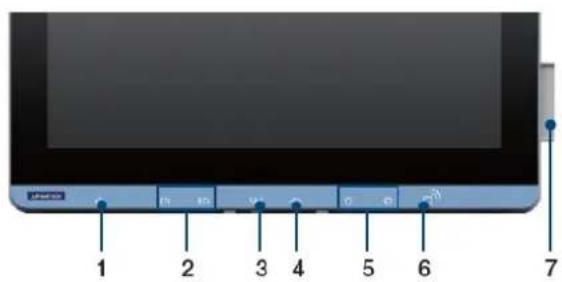
Figure 1.5 POC-615-12 series front panel
- Power button
- Volume down/up
- Touchscreen status control
-
Read light control
-
Brightness down/up
- RFID reader (optional)
- Smart card reader (optional)
choose either RFID or smart card reader)
1.4 Optional Modules
Memory: Up to 64GB DDR4 SODIMM
Primary Storage: NVMe (M2 2280, PCIe interface)
Wi-Fi and Bluetooth Module: Intel® Wi-Fi 6E AX210 and Intel Wireless-AC9260
RFID Module: RFIDEAS KT-805N64KU
Smart card
■ Backup Battery: Internal backup battery, POC-BAT-101-6A, lithium-ion 8400mAh 10.8V 90.72Wh 3S3P)
Camera: 5MP auto focus
Touchscreen: Projected capacitive / optional AR/AG coating
The above optional modules might be mutually exclusive from each other. Contact Advantech for more details.
1.4.1 Cleaning and Disinfecting
During normal use of the POC (Point-of-Care terminal) the device may become dirty and should be regularly cleaned.
Steps:
- Prepare cleaning liquid.
- Wipe the POC with a clean cloth that has been moistened in a cleaning solution.
- Wipe thoroughly with a clean cloth.
Caution!

- Do not immerse or rinse the POC or its peripherals. If you accidentally spill liquid on the device, disconnect the unit from the power source. Contact your IT support department regarding the continued safety of the unit before placing it back in operation
Do not spray cleaning agent on the chassis.
Do not use disinfectants that contain phenol. - Do not autoclave or clean the POC or its peripherals with strong aromatic, chlorinated, ketone, either, or ether solvents, sharp tools or abrasives. Never immerse electrical connectors in water or other liquids.
Attention!

1.5 Operating Principle
The device provides input through a touch panel, hard keys located at the bottom, accessories through USB ports, or its LAN/WLAN connections. The device computes the input data with its processing unit and then outputs the generated data to the LCD panel, accessories, other devices through its I/O ports, or through its LAN/WLAN connections. The device is able to store data, and when the device is turned off, will still maintain the data in storage.
1.6 Intended User Profile
Intend User Profile:
Age: 18 to 65
Weight: not relevant
Health: not relevant
Nationality: Global
Patient state: patient will not be the operator.
Part of the body or type of tissue applied to or interacted with: hands and fingers, expected contact time shall be less than 1 min.
Education level: at least 8 years intensive reading experience (school)
Knowledge:
Minimum - read and understand "westernized Arabic" numerals when written in Arial font
- Can distinguish: every parts of body as described in user manual
- Trained and authorized by manufacturer only.
To be considered as trained and authorized, they must complete the training course of the manufacturer; see document number xxxx for qualification method, when considered necessary by the manufacturer, technician shall be called back for retraining and annual training is also considered necessary.
Language understanding: English, whenever other languages are required, professional translation company shall translate and review by the manufacturer, see SOP document number:XXXXX
Experience: Mentally and physical competent, specific medical training to understand basic knowledge for symbols.
Permissible impairments:
- Mild reading vision impairment or vision corrected to log MAR 0,2 (6/10 or 20/32)
One arm / hand system capable of guiding and holding device
Average degree of aging-related short term memory impairment - impaired by 40% resulting in 60% of normal hearing at 500Hz to 2kHz
Chapter 2
System Setup
2.1 A Quick Tour of the POC-615-12 Series
Before you start to set up the POC-615-12 Series, take a moment to become familiar with the locations and purposes of the controls, drives, connections and ports, which are illustrated in the figures below.
When you place the POC-615-12 Series upright on the desktop, its front panel appears as shown in Figure 2.1.
2.1.1 Front View
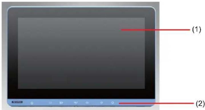
Figure 2.1 Front view of the point-of-care terminal
Front bezel view
(1) LCD panel with touch screen module
(2) Power symbol w/ indicator light
2.1.2 Rear View
When you turn the point of care terminal around and look at its rear cover, the sunken I/O section is at the bottom of the panel PC, as shown in Figure 2.2 and zoom in on Figure 2.3. (The I/O section includes various I/O ports, including serial ports, HDMI port, the Ethernet port, USB ports, and so on.)
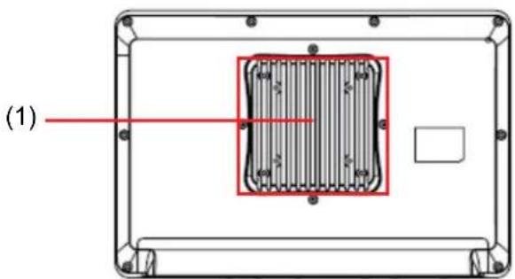
Figure 2.2 Rear view of the point of care terminal
- PCIe x4 slot
6.1xUSB3.2(TypeC)
Note! Equipotential terminal needs to be linked to hospital ground/earth system before system boot to protect the operator and system.

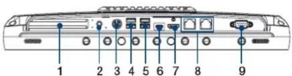
Figure 2.3 Rear view of multi I/O ports (AC-in model)
2.2 Installation Procedures
2.2.1 Connecting the Power Cord
The POC-615-12 series can be powered by a DC adapter (SINPRO Model no. HPU150A-107 or DELTA model no. MDS-150AAS19F). Be sure to always handle the power cords by holding the plug ends only.
Follow these procedures in order:
- Connect the female end of the power cord to the AC adapter.
- Connect the 3-pin male plug of the power cord to an electrical outlet.
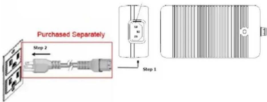
Figure 2.4 Connecting the power cord
2.2.2 Connecting the DCIN
AC Adapter output DCIN plug output the DC power for POC system. Please plug in to POC DCIN.
Caution! Adapter DCIN plug has a specific direction. Please align the plug and DCIN connector correctly.


Warning! Miss direction when plugging in may damage the POC system or adapter.

2.2.3 Connecting the Ground Pin
- System ready and find the Equipotential terminal on rear side of POC. An Equipotential terminal is providing to optionally connect to a hospital ground/ earth system
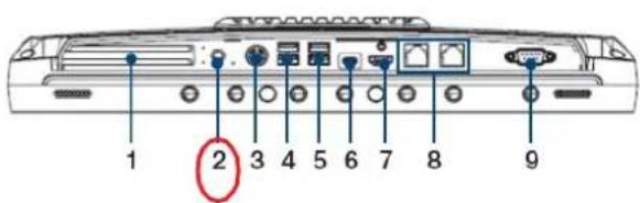
Figure 2.5 POC-615-12 SERIES Equipotential Terminal Pin
1.PCle x4 slot
2. Equipotential terminal pin
3.DC-in
4.2xUSB3.2
5.2XUSB3.2
6.1xUSB3.2(TypeC)
7.HDMI
8.2 x Gigabit Ethernet
9.1xCOM(RS-232)
- Prepare the grounding cable and the other terminal link to hospital ground/earth system.
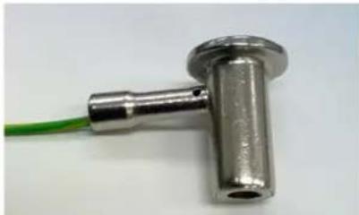
Figure 2.6 Grounding cable with connector
- Grounding cable plug with POC-615-12 SERIES Equipotential terminal (see Figure 2.6)
2.3 Running the BIOS Setup Program
Your POC-615-12 was probably set up and configured by your dealer prior to delivery. You may still find it necessary to use the BIOS (Basic Input-Output System) setup program to change system configuration information, such as the current date and time or your type of hard drive. The setup program is stored in read-only memory. It can be accessed either when you turn on or reset the panel PC by pressing the "F2" or "Del" key on your keyboard immediately after powering on the computer.
The settings you specify with the setup program are recorded in a special area of memory called CMOS RAM. This memory is backed up by a battery so that it will not be erased when you turn off or reset the system. Whenever you turn on the power, the system reads the settings stored in CMOS RAM and compares them to the equipment check conducted during the power on self-test (POST). If an error occurs, an error message will be displayed on screen, and you will be prompted to run the setup program.
2.4 Installing System Software
Recent releases of operating systems from major vendors include setup programs which load automatically and guide you through hard disk preparation and operating system installation. The guidelines below will help you determine the steps necessary to install your operating system on the panel PC hard drive.
Note!
Some distributors and system integrators may have already preinstalled system software prior to shipment of your panel PC.

If required, insert your operating system's installation or setup diskette into the external diskette drive until the release button pops out.
The BIOS supports system boots up directly from the Flash disk. You may also insert your system installation Flash disk into USB port.
Power on or reset the system by pressing the "Del" key to boot into the BIOS menu and adjust the boot device sequence.
You can also press the F12 key when booting. A bootable device popup menu will appear. You can select the bootable device you prefer. The point-of-care terminal will automatically load the operating system from the flash disk.
If you are presented with the opening screen of a setup or installation program, follow the instructions on screen. The setup program will guide you through preparation of your hard drive, and installation of the operating system.
2.5 Installing the Drivers
After installing your system software, you will be able to set up the chipset, graphics, Ethernet, and audio functions by driver.
The standard automatic installation procedures for installing the drivers are described in later chapters.
The various drivers and utilities in the CD-ROM disc have their own text files which help users install the drivers and understand their functions. These files are a very useful supplement to the information in this manual.
All driver could download from Advantech website.
2.6 Troubleshooting
When system behaves abnormally, such as below condition:
Please refer below instruction to troubleshoot.
2.6.1 POC Not Powering ON
Press the power button but no power on (Power ON Green indicator still off)
Please check:
- Check Adapter/DCIN plugin properly.
- Check Adapter/DCIN plug in correct direction to POC DCIN Connector
- Check AC Power cord plug in adapter properly
- Check AC Power cord plug in wall inlet properly.
- If no adapter plugin (battery powered mode), please check battery install properly and the battery capacity.
Please unplug the battery pack and press the capacity indicator button on battery pack.

The illuminated LED represents the battery capacity.
| State-of-Charge | |
| LED Green | Current() > 0 |
| LED1 | 0%~20% |
| LED2 | 0~40% |
| LED3 | 0~60% |
| LED4 | 0~80% |
| LED5 | 0~100% |
2.6.2 Adapter Power LED OFF.
Adapter indicator green LED remain off.
- Check AC power cord plug in adapter properly
- Check AC power cord plug in wall inlet properly.
2.6.3 POC System Powers On but Not Booting Windows
POC display show black background and show some words.
- Check if Windows OS is installed properly.
- Check if the BIOS boot order is set properly. Please setup BIOS boot device by following the below procedure:
a) press the "Del" key at power up, into the BIOS Menu.
b) In Boot - Boot Option #1 - Select "Windows Boot Manager (Storage name)"
c) In Save & Exit - Save Changes and Reset - Select Yes
d) POC system will reset and boot up.
2.6.4 AC Powers and All Indicator ON, but System Doesn't Power On
Both adapter indicator green LED and POC system power on indicator green LED are on.
Please contact Advantech customer service for further support.
2.6.5 No Charge
Please check:
- Battery pack is installed properly. Please push pack inside the battery slot.
- Check if the DC-IN is plugged in properly.
- In battery design, the battery capacity should be under 98% to initiate the charge.
This design can avoid frequent charging.
In other words word, if battery capacity is 99% or 100% , the charger will not charge the battery.
Contact your distributor, sales representative, or Advantech's customer service center for technical support if you need additional assistance. Please have the following information ready before you call:
Product name and serial number
Description of your peripheral attachments
Description of your software (operating system, version, application software, etc.)
A complete description of the problem
The exact wording of any error messages
Symptoms, photo or video if available
2.7 EMC Declaration
| Guidance and manufacturer's declaration – electromagnetic emissions | ||
| The model POC-615-12 SERIES is intended for use in an electromagnetic environment as specified below. The customer or the user of the POC-615-12 SERIES should assure that it is used in such an environment. | ||
| Emissions test Compliance | Electromagnetic environment – guidance | |
| RF emissions CISPR 11 | Group 1 | The model POC-615-12 Series uses RF energy only for its inter-nal function. Therefore, its RF emissions are very low and are not likely to cause any interfer-ence in nearby electronic equip-ment. |
| RF emissions CISPR 11 | Class B | The model POC-615-12 Series is suitable for use in all establish-ments, including domestic estab-lishments and those directly connected to the public low-volt-age power supply network that supplies buildings used for domestic purposes. |
| Harmonic emissions IEC 61000-3-2 | Class D | |
| Voltage fluctuations/ flicker emissions IEC 61000-3-3 | Meet the require-ments | |
| Recommended Separation Distances Between Portable And Mobile Rf Communications Equipment And The Model POC-615-12 Series | |||
| POC-615-12 SERIES is intended for use in an electromagnetic environment in which radiated RF disturbances are controlled. The customer or the user of the model POC-615-12 can help prevent electromagnetic interference by maintaining a minimum distance between portable and mobile RF communications equipment (transmitters) and the model POC-615-12 SERIES as recommended below, according to the maximum output power of the communications equipment. | |||
| Rated maximum output power of transmitter W | Separation distance according to frequency of transmitter m | ||
| 150 kHz to 80 MHz d = 1,2√P | 80 MHz to 800 MHz d = 1,2√P | 800 MHz to 2,5 GHz d = 2,3√P | |
| 0,01 0,12 0,12 0,23 | |||
| 0,1 0,38 0,38 0,73 | |||
| 1 1,2 1,2 2,3 | |||
| 10 3,8 3,8 7,3 | |||
| 100 12 12 23 | |||
| For transmitters rated at a maximum output power not listed above, the recommended separation distance d in metres (m) can be estimated using the equation applicable to the frequency of the transmitter, where P is the maximum output power rating of the transmitter in watts (W) according to the transmitter manufacturer. NOTE 1 At 80 MHz and 800 MHz, the separation distance for the higher frequency range applies. NOTE 2 These guidelines may not apply in all situations. Electromagnetic propagation is affected by absorption and reflection from structures, objects and people. | |||
| Guidance and Manufacturer's Declaration - Electromagnetic Immunity | |||
| POC-615-12 SERIES is intended for use in the electromagnetic environment specified below. The customer or the user of the model POC-615-12 SERIES should assure that it is used in such an environment. | |||
| Immunity test | IEC 60601 test level | Compliance level | Electromagnetic environment-guidance |
| Electrostatic discharge (ESD)IEC 61000-4-2Electrical fast transient/burstIEC 61000-4-4SurgeIEC 61000-4-5 Interruptions and voltage variations on power supply input linesIEC 61000-4-11Power frequency (50/60 Hz)magnetic fieldIEC 61000-4-8 | ±8 kV contact±15 kV air±2 kV for power supply lines±1 kV for input/out put lines±1 kV line(s) to line(s)±2 kV line(s) to earthVoltage Dips: i) 0% reduction for 0.5 cycle at 50Hz,0% reduction for 1 cycle at 50Hz Performance Criterion Bii) 70% reduction for 25/30 cycles at 50/60HzPerformance Criterion CVoltage Interruptions: 0% reduction for 250/300 cycles at 50/60HzPerformance Criterion C30A/m | ±8 kV contact±15 kV air±2 kV for power supply lines±1 kV for input/output lines±1 kV line(s) to line(s)±2 kV line(s) to earthVoltage Dips: i) 0% reduction for 0.5 cycle at 50Hz,0% reduction for 1 cycle at 50HzPerformance Criterion Bii) 70% reduction for 25/30 cycles at 50/60HzPerformance Criterion CVoltage Interruptions: 0% reduction for 250/300 cycles at 50/60HzPerformance Criterion C30A/m | Floors should be wood, concrete or ceramic tile. If floors are covered with synthetic material, the relative humidity should be at least 30%.Main power quality should be that of a typical commercial or hospital environment.Main power quality should be that of a typical commercial or hospital environment.Main power quality should be that of a typical commercial or hospital environment. If the user of the model POC-615-12 requires continued operation during main power interruption, it is recommended that the model POC-615-12 be powered from an uninterruptible power supply.Power frequency magnetic fields should be at levels characteristic of a typical location in a typical commercial or hospital environment. |
| NOTE UT is the A.C. mains voltage prior to application of the test level. | |||
| The model POC-615-12 SERIES is intended for use in the electromagnetic environment specified below. The customer or the user of the model POC-615-12 SERIES should assure that it is used in such an environment. | |||
| Immunity test | IEC 60601 test level | Compliance level | Electromagnetic environment - guidance |
| Conducted RFIEC 61000-4-6Radiated RFIEC 61000-4-3 | 3 and 6 Vrms150 kHz to 80 MHz and specific ISM, AM fre-quency3 and 6 Vrms3V/m80 MHz to 2.7 GHz, and specific frequency | 3 and 6 Vrms150 kHz to 80 MHz and specific ISM, AM frequency3V/m80 MHz to 2.7 GHz, and specific fre-quency | Portable and mobile RF communications equipment should be used no closer to any part of the model POC-615-12 Series, including cables, than the recommended separation distance calculated from the equation applicable to the frequency of the transmitter.Recommended separation distanced=1,2√Pd=1,2√80 MHz to 800 MHzd=2,3√800 MHz to 2,5 GHzwhere P is the maximum output power rating of the transmitter in watts (W) according to the transmit-ter manufacturer and d is the recommended separation distance in metres (m).Field strengths from fixed RF trans-mitters, as determined by an elec-tromagnetic site survey, a should be less than the compliance level in each frequency range. bInterference may occur in the vicinity of equipment marked with the fol- lowing symbol:((●)) |
| NOTE 1 At 80 MHz and 800 MHz, the higher frequency range applies.NOTE 2 These guidelines may not apply in all situations. Electromagnetic propagation is affected by absorption and reflection from structures, objects and people. | |||
a Field strengths from fixed transmitters, such as base stations for radio (cellular/cordless) telephones and land mobile radios, amateur radio, AM and FM radio broadcast and TV broadcast cannot be predicted theoretically with accuracy. To assess the electromagnetic environment due to fixed RF transmitters, an electromagnetic site survey should be considered. If the measured field strength in the location in which the model POC-615-12 Series is used exceeds the applicable RF compliance level above, the model POC-615-12 Series should be observed to verify normal operation. If abnormal performance is observed, additional measures may be necessary, such as reorienting or relocating the model POC-615-12 Series.
b Over the frequency range 150kHz to 80MHz , field strengths should be less than 3V / m .
Chapter 3
Operation and Safety
3.1 General Safety Guide
For your own safety and that of your equipment, always take the following precautions.
Disconnect the power plug (by pulling the plug, not the cord), from your computer if any of the following conditions exist:
The power cord or plug is frayed or otherwise damaged.
Any substance is spilled on the POC system.
The POC system has been dropped or the case has been damaged.
The POC system needs servicing or repair.
To clean the POC system.
To remove/install any internal parts (exclude install/took out hotswap battery pack)
3.2 Thermals
The vent hole of the POC Series rear cover functions as a cooling air flow inlet and outlet. These air inlets and outlets transfer heat from inside the computer to the cooler air outside. Do not block these holes/vents with any soft material.
When using your POC SERIES system, it is normal for the rear metal heatsink to get warm. The rear metal heatsink of the POC Series functions as a cooling surface that transfers heat from inside the computer to the cooler air outside.
Do not block this heatsink with any soft material.
To protect the battery pack from overheating, use/charge the battery in accordance with the instructions provided in the user manual.
Warning!
- Temperatures that are too high or too low may damage the battery.

- Do not place your POC system on a pillow or other soft material when it is on, as the material may block the airflow and cause the system to overheat.
Avertissement!
Charge battery and use it in accordance with datasheet specifications..
Warning!
- If the temperature is too high or too low, your batteries may be damaged.

- If the temperature is too high or too low, your batteries may stop charge. Battery could restart charge when its temperature returns to specific temperature.
Avertissement!
3.3 Disconnect the Power
The only way to disconnect the power completely is to unplug the power cord. Make sure at least one end of the power cord is within easy reach so that you can unplug the computer when you need to.
Warning!
Your AC cord came equipped with a three-wire grounding plug (a plug that has a third grounding pin). This plug will fit only a grounded AC outlet. If you are unable to insert the plug into an outlet because the outlet is not grounded, contact a licensed electrician to replace the outlet with a properly grounded outlet.
Do not defeat the purpose of the grounding plug.
Avertissement!

Never push objects of any kind into this product through the openings in the case.

Doing so may be dangerous and result in fire or a dangerous electric shock.
Never place anything on system case before turning off the computer.
Never turn on your computer unless all of its internal and external parts are in place.
Operating the computer when it is open or missing parts can be dangerous and can damage your computer.
Avertissement!

Handle your POC system with care. The system is made of metal, glass and plastic and contains sensitive electronic components. Because the POC system is a heavy object, please use two hands to handle it.
Hold the battery with both hands when installing, removing, or replacing a battery pack.
Warning! Do not attempt to use the POC system if it is damaged (for example, the case is cracked or broken) as this may cause injury.
Caution! 1) Setup and install POC system on a stable work surface.
2) Do not push objects into the ventilation openings.
3) This SINPRO HPU150A-107 and DELTA MDS-150AAS19F adapter are medical grade adapter.
Please read these safety instructions and warnings before using or charging the battery.
Warning! Li-ion battery packs may explode and cause fire if defective or used incorrectly. To prevent this from happening, follow all usage instructions and safety guidelines provided in this user manual.
- Removal of the POC system battery pack and unplugging of the power cord will cause the connected POC system shut down, which may result in data losses. To prevent the loss of information, always save your work and shut down the POC system via the Windows OS before removing the battery or power cord.
- Lithium batteries have a predetermined life span. Replace old batteries with new batteries when they have reached the end of their service life (the warranty is for 1 year or 300 cycles with 70% normal capacity, according to which occurs first).
Attention!
3.6 Battery Safety Instruction
- The POC system should only be powered by an Advantech battery pack or compatible battery pack supplied by Advantech.
Warning!
- Do not insert non-Advantech battery packs into the POC system.
- Do not attempt to use battery packs of a different brand.

Avertissement!
Batteries installed in the wrong direction with the opposite polarity are at risk of exploding, which may cause fire.

Avertissement!
- Only use the specific battery charger provided by Advantech to charge the battery pack.
Warning! Using a battery charger of a different brand may cause the battery to explode and result in fire.

- Do not short the battery pack connector using a metal or wire lead.
Warning! Wire lead shorts can cause the battery to explode and result in fire.

- Do not drop the battery pack.
Warning! If the battery cover is cracked, split, or broken, do not use the battery.

- Do not expose the battery pack to fire or high temperatures.
Warning! Exposure to high temperatures may cause the battery to explode.

- Do not penetrate the battery with nails, strike the battery with a hammer, step on the battery, or otherwise subject it to significant impact or shock.
Warning! Batteries are at risk of exploding and may cause fire if subjected to significant impact.

- Do not expose the battery pack to moisture or water.
- Do not disassemble or modify the battery pack. The battery pack contains safety and protection circuits that if damaged, may cause the battery to overheat, explode, or ignite. There are no user-serviceable parts inside the battery pack.
- Always refer to the user manual for charging instructions.
- Charge the battery pack in indoor environments with a controlled temperature.
Caution! Exposure to extreme temperatures can damage the battery and reduce the battery life capacity.

- Do not leave fully charged battery packs connected to the computer for prolonged periods of time.
Caution! When the battery is fully recharged, disconnect it from the charger or unplug the charger power cable.

- Do not discharge the battery pack using any device other than the POC system or a device specified by Advantech.
Warning!
Using the battery pack to power devices other than the POC system may damage the battery, limit performance, or reduce the battery life capacity. Additionally, exposure to abnormal current may cause the battery pack to overheat, explode, or ignite, causing serious injury.
Avertissement!
- Use/discharge the battery pack in indoor environments with a controlled temperature.
Caution!
Using the battery in environments with temperatures outside the acceptable range may damage the battery, limit performance, or reduce the battery life capacity.

Attention!
- Inspect all battery packs before use.
Warning!
1) Never use battery packs that are visibly damaged or that may have internal damage.

2) Never remove the battery's outer cover or use a battery pack with a damaged cover.
Avertissement!
- Replace the entire battery pack with a new battery pack when the time between charges decreases significantly.
Caution!
When the time between charges decreases significantly, check the voltage of the battery pack before charging. If the battery performance drop significantly, please do not use this battery pack.

Attention!
If you notice any of the following, stop charging or using the battery immediately:
- The battery has become swollen, bulging, or deformed.
- The battery is leaking fluid, smoke, or a foul odor.
- The battery temperature is extremely hot.
- The battery appears abnormal in any way
- The battery cover is cracked, split, or broken.
- The battery has been exposed to moisture.
Warning!
- If any of the above conditions are observed, place the battery pack and charger outside on a concrete floor, away from any flammable materials for approximately 15 minutes and contact Advantech. Do not attempt to reuse the battery pack.
- In the event that the battery is leaking and the fluid gets into your eye, rinse well with water and immediately seek medical care. If left untreated, exposure to battery fluid could damage your eye.
Avertissement!

3.8 Battery Storage and Transportation
- Store the battery in a dry environment with a room temperature of 0 25°C (32 77°F ) for optimum health.
- Do not expose the battery pack to direct sunlight (heat) or store the battery pack inside vehicles in hot weather for extended periods.
- When transporting or temporarily storing the battery in a vehicle, the internal vehicle temperature should be greater than -20°C (-4°F) but no more than 50°C (122°F) .
- If possible, remove the battery pack from the device if the device will be unused for several months.
- Do not remove individual battery packs from the original packaging until required for use.
Warning! To reduce the risk of damage, do not expose battery packs to high temperatures for extended periods of time. This may damage the battery and cause fire.
Caution! 1. Stored batteries should be checked every 3 months. If the capacity is less than 50% , recharge the battery before returning it to storage.
2. Batteries may leak if left in the device for extended periods of time. After long periods of storage, check the battery pack before charging.
3.9 Battery Disposing
When the battery pack has reached the end of its service life, do not use general household waste for disposal. Follow local laws and government regulations for correct battery disposal.
Caution!
Cover terminals with tape to prevent inadvertent contact with other batteries or metal objects. Cover terminals with tape to prevent inadvertent contact with other batteries or metal objects.

Warning!
- To reduce the risk of fire or burns, do not disassemble, crush, puncture, expose to fire or water, or short the battery's external contacts.
- Used batteries may still have a partial charge. If partially charged batteries come into contact with other batteries or metal objects, the remaining stored energy may be discharged and cause a fire or explosion.

Attention!
Installing VESA Mount
4.1 Installing the VESA Mounting
The POC Series also provides standard VESA mounting to help system integrators conveniently integrate the panel PC into their system.
Never use mounting brackets except as provided by Advantech to prevent unreliable mounting of the POC series. VESA mount installation should be carried out by a professional technician; please contact a service technician or your retailer if you need this service.
Installation instructions follow:
- First attach the wall-mounting to the Heat-sink of the POC-615-12 Series, securing it in place with four of the philips head screws provided.
- Mount the on the wall, stand, or other flat surface.
Warning! Be sure to secure the screws of the mounting bracket tightly. A loose joint between the POC Series and mounting bracket may create danger of injury.
Avertissement!
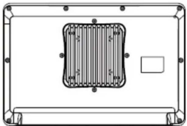
Figure 4.1 VESA mounting
Chapter 5
Driver Installation
5.1 Driver Installation
The POC system supports Windows WIN10 IOT/RS5 version or later, 64-bit only. It no longer supports 32-bit drivers.
Warning! Please use clean a clean OS to install drivers, otherwise, it might cause unexpected errors.

Please follow your OS version to install proper drivers.
Please follow the below sequence to install drivers.
Table 5.1: Driver installation sequence
| Install sequence Folder Name Note | ||
| 1 Chipset Please install chipset driver first. | ||
| 2 Graphics | IGCC (Intel Graphics Command Center) is no longer combined with driver. After graphics driver installation is complete, please install IGCC by powershell. | |
| 3 Audio | ||
| 4 LAN | ||
| 5 AMT Intel management engine driver | ||
| 6 RST Intel rapid storage technology | ||
| 7 | Wireless Card (Wi-Fi + Bluetooth) | Optional |
| 8 RFID | Optional | |
| 9 Smart Card | Optional | |
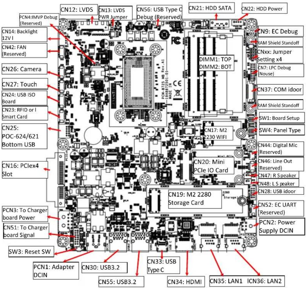
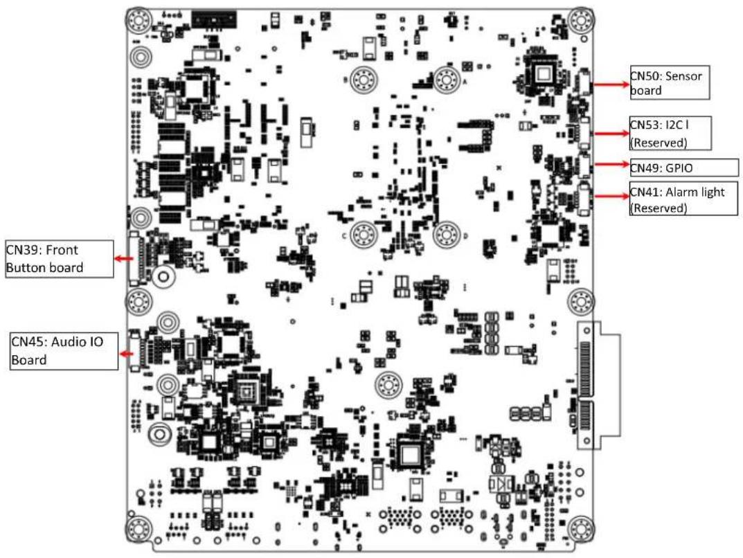
Chapter 6
PCM-8725 Connector Map
6.1 POC System Uses PCM-8725 PCBA
MB top side
Bottom
Chapter 7
PCM-8725 Jumper Settings
7.1 PCM-8725 Jumper Settings
The POC system uses PCM-8725 PCBA. All jumpers/DIP switches are located on the MB top side
MB Top Side
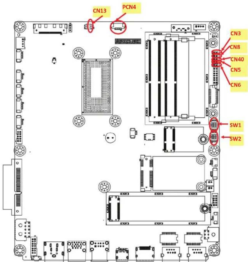
Jumper Settings
MB:
Table 7.1: Jumper settings
| CN3 | ME Manufacturing Mode |
| CN5 | Clear CMOS |
| CN6 | Clear ME (reserved, not installed) |
| CN8 | System reset (reserved, not installed) |
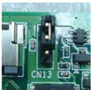
| CN13 | LVDS voltage |
| CN40 | Power button (reserved, internal test only) |
| PCN4 | Power debug (reserved) |
| SW1 | Board setup |
| SW2 | Panel setup |
Table 7.2: CN3 ME manufacturing mode
Description ME manufacturing mode
Setting Function
(1-2) ME manufacturing mode
(No Connect) Normal operations (default)

Table 7.3: CN5 clear CMOS
| Description Clear CMOS setup |
| Setting Function |
| (1-2) Clear CMOS setup |
| (No Connection) Normal operations (default) |

Table 7.4: CN6 (not installed) clear ME
| Description Clear ME setup |
| Setting Function |
| (1-2) Clear ME setup |
| (No Connect) Normal operations (default) |

Table 7.5: CN8 system reset
| Description Reset system button |
| Setting Function |
| (1-2) System reset |
| (No Connect) Normal Operation (Default) |

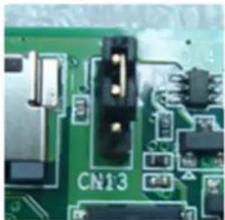
Table 7.6: CN13 LVDS voltage setup
Description Select panel LVDS voltage setting
Settings Function
(1-2) Panel LVDS voltage 5 V (default)
(2-3) Panel LVDS voltage 3.3 V
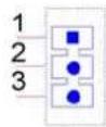
Table 7.7: CN40 power button (reserved, internal test only)
Description Power Button Signal
Settings Function
(Pin 2) Short pin 1 to power ON system
(No Connection) Normal operations (default)

Table 7.8: PCN4 power debug (reserved)
Description Power debug, internal test only
Settings Function
(No Connection) Normal operations (default)

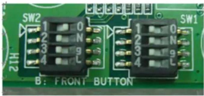
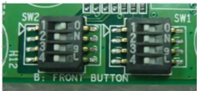
Table 7.9: SW1 board setup
Description Select board setting
Setting Function
(SW1-1/2/3) Select board type
(SW1-4) Force speaker always ON

Table 7.10: Board configurations
| SW1 pin 1 SW1 pin 2 SW1 pin 3 Board Configuration |
| Hi (OFF) Hi (OFF) Hi (OFF) Board Config 1 (default) |
| Hi (OFF) Hi (OFF) Low (ON) Board Config 2 |
| Hi (OFF) Low (ON) Hi (OFF) Board Config 3 |
| Hi (OFF) Hi (OFF) Hi (OFF) Board Config 4 |
| Low (ON) Hi (OFF) Hi (OFF) Board Config 5 |
| Low (ON) Hi (OFF) Low (ON) Board Config 6 |
| Low (ON) Low (ON) Hi (OFF) Board Config 7 |
| Low (ON) Hi (OFF) Hi (OFF) Board Config 8 |
Table 7.11: SW1 pin 4 speaker functions
| Hi (OFF) | Speaker mutes when audio plugs in – with audio board system default |
| Low (ON) | Speaker always ON – without audio board system default |
Table 7.12: SW4 panel resolution/type setup
| Description Select panel settings |
| Setting Function |
| (SW2-1~4) Select panel type |

Table 7.13: SW4 Pins
| SW4 Pin 1 SW4 Pin 2 SW4 Pin 3 SW4 Pin 4 Panel Resolution LVDS Channel | |||||
| Hi (OFF) | Hi (OFF) | Hi (OFF) | Hi (OFF) | 1920 x 1200 | 24-bit dual |
| Low (ON) | Hi (OFF) | Hi (OFF) | Hi (OFF) | 1920 x 1080 (default) | 24-bit dual |
| Hi (OFF) | Hi (OFF) | Low (ON) | Hi (OFF) | 1600 x 900 | 24-bit dual |
| Low (ON) | Low (ON) | Low (ON) | Hi (OFF) | 1366 x 768 | 24-bit single |
| Low (ON) | Hi (OFF) | Hi (OFF) | Low (ON) | 1280 x 1024 | 24-bit dual |
| Low (ON) | Hi (OFF) | Low (ON) | Low (ON) | 1024 x 768 | 24-bit single |
| Low (ON) | Low (ON) | Low (ON) | Low (ON) | 800 x 600 | 18-bit single |
For Different system summary
POC-615-12 System setting
POC-615-12, with audio board, 5 V LVDS panel
| Table 7.14: 5 V LVDS panel | |||||||||
| SW1 Pin | SW1 Pin | SW1 Pin | SW1 Pin | SW2 Pin | SW2 Pin | SW2 Pin | SW2 Pin | CN1 | |
| 1 | 2 | 3 | 4 | 1 | 2 | 3 | 4 | 3 | |
| Hi (OFF) | Hi (OFF) | Hi (OFF) | Hi (OFF) | Low (ON) | Hi (OFF) | Hi (OFF) | Hi (OFF) | (1-2) | |
POC-615-12 System
POC-615-12, with audio board, 3.3V LVDS panel
| Table 7.15: SW1 +SW2 pins | |||||||||
| SW1 Pin | SW1 Pin | SW1 Pin | SW1 Pin | SW2 Pin | SW2 Pin | SW2 Pin | SW2 Pin | CN1 | |
| 1 | 2 | 3 | 4 | 1 | 2 | 3 | 4 | 3 | |
| Hi (OFF) Hi (OFF) Hi (OFF) Low (ON) Low (ON) Hi (OFF) Hi (OFF) Hi (OFF) (2-3) | |||||||||
Chapter 8
Front Bezel Button
8.1 Introduction
The POC system front button function description
Front button map


Button descriptions:
| Power button | Press this button to power on/off the system. When the system is ON, this icon will become green and the LED will be off when the system is off. | |
| Reduce volume | Press this button to reduce speaker and headphone volume. | |
| Increase Volume Press this button to increase speaker and headphone volume. | ||
| Touch disable | Press this button to disable/enable touch function. When touch function is enabled, this icon will become green. When the touch function is disabled, this LED light will be off. | |
| Read light Press this button to enable/disable the read light. | ||
| Reduce brightness | Press this button to reduce LCD backlight brightness. | |
| Increase brightness | Press this button to increase LCD backlight brightness. | |
Combination button:
A special function is the backlight off function. When you press both reduce brightness and increase brightness buttons for a half second the LCD backlight will be turned off. Press both buttons for a half second again the LCD backlight will be turned back on. When the backlight is off, the POC system is still running, and not impacting any program operations. The backlight off function can be used in hospital environments. If operators need to check the photo in a dark room environment, operators can turn off the backlight quickly to prevent interference in a dark room environment. Operators can turn off the backlight at night to prevent interfering with a patient's sleep. The backlight will automatically turn back on when the system is shut down and powered back up.
Chapter 9
Advanced BIOS Function
9.1 Advanced BIOS Function
Introduce the advanced function in POC system BIOS menu.
1. Power Button Function Enable/Disable
You can enable/disable power button function in BIOS menu.
If you disable the power button in S0 (System ON) status, power button will not work. So the user cannot turn off the system by power button. User need to use software to turn off system. This function can prevent mis-touch the power button to shutdown system.
BIOS Menu location:
BIOS Menu - Advanced - IT5121 HW Monitor - Power Button Function
■ Enable: Power button function work when system in S0 (System ON) status. (Default)
- Disable: Power button function not work when system in S0 (System ON) status.
Because disable the power button function will cause system cannot power on by power button pressed. When you set this function to disable, BIOS will set the "State After G3" to "Power On" automatically. So you can plugin power adapter to turn on POC system.
2. Brightness Button Control
You can enable/disable LCD Backlight button function in BIOS menu.
If you disable the LCD Backlight button, this button will not work. So the user cannot adjust LCD backlight luminance by this button. This function can prevent mis-touch the LCD backlight button to adjust the LCD backlight luminance.
BIOS Menu location:
BIOS Menu - Advanced - IT5121 HW Monitor - Brightness Button Control
Enable: Front bezel LCD Backlight adjust button control function work. (Default)
- Disable: Front bezel LCD Backlight adjust button control function not work.
3. Volume Button Control
You can enable/disable Front volume button function in BIOS menu.
If you disable the Front volume button, this button will not work. So the user cannot adjust speaker volume by this button. This function can prevent mis-touch the front volume button to adjust the speaker volume.
BIOS Menu location:
BIOS Menu - Advanced - IT5121 HW Monitor - Volume Button Control
■ Enable: Front bezel volume adjust button control function work. (Default)
- Disable: Front bezel volume adjust button control function not work.
4. Touch Button Control
You can enable/disable Touch button function in BIOS menu.
If you disable the Touch button, this button will not work. So the user cannot turn off touch by this button. The touch function will always on.
BIOS Menu location:
BIOS Menu - Advanced - IT5121 HW Monitor - Touch Button Control
■ Enable: Front bezel Touch button control function work. (Default)
- Disable: Front bezel Touch button control function not work.
5. Read light Button Control
You can enable/disable Read light button function in BIOS menu.
If you disable the Read light button, this button will not work. So the user cannot turn on read light by this button. The read light function will always off.
BIOS Menu location:
BIOS Menu - Advanced - IT5121 HW Monitor - Read light Control
■ Enable: Front bezel Read light button control function work. (Default)
- Disable: Front bezel Read light button control function not work.
6. EC Beep Function
You can enable/disable EC beep function in BIOS menu.
If you disable the EC beep function, EC will not generate beep sound when you press front bezel button.
BIOS Menu location:
BIOS Menu - Advanced - IT5121 HW Monitor - Beep Sound Function
Enable: Beep sound when front bezel button pressed. (Default)
- Disable: No beep sound when front bezel button pressed.
7. SETUP POPUP MENU F12
You can press F12 key Setup popup menu in system boot.
When you press F12 key in bootup, BIOS will display a bootable device menu and you can select proper boot device that you want.
www.advantech.com
Please verify specifications before quoting. This guide is intended for reference purposes only.
All product specifications are subject to change without notice.
No part of this publication may be reproduced in any form or by any means, electronic, photocopying, recording or otherwise, without prior written permission of the publisher.
All brand and product names are trademarks or registered trademarks of their respective companies.
© Advantech Co., Ltd. 2024

- INSTRUCTIONS FOR THE USER
- DEFINITIONS
- SAFETY INSTRUCTIONS
- CAUTION
- MEDICAL-GENERAL MEDICAL EQUIPMENT
- NOTE
- EXPLANATION OF GRAPHICAL SYMBOLS
- DISPOSING OF OLD PRODUCTS
- FCC CLASS B
- AVERTISSEMENT
- ADDITIONAL INFORMATION AND ASSISTANCE
- ENVIRONMENTAL PROTECTION
- MANUFACTURER
- DISTRIBUTED IN EUROPE BY
- CONTENTS
- CHAPTER 1 GENERAL INFORMATION
- CHAPTER 2 SYSTEM SETUP. 9
- CHAPTER 3 OPERATION AND SAFETY 21
- CHAPTER 4 INSTALLING VESA MOUNT. 33
- CHAPTER 5 DRIVER INSTALLATION 35
- CHAPTER 6 PCM-8725 CONNECTOR MAP. 37
- CHAPTER 7 PCM-8725 JUMPER SETTINGS. 41
- CHAPTER 8 FRONT BEZEL BUTTON. 47
- CHAPTER 9 ADVANCED BIOS FUNCTION 49
- CHAPTER 1
- 1.1 INTRODUCTION
- 1.2 SPECIFICATIONS
- 1.3 DIMENSIONS
- 1.4 OPTIONAL MODULES
- 1.4.1 CLEANING AND DISINFECTING
- STEPS
- ATTENTION
- 1.5 OPERATING PRINCIPLE
- 1.6 INTENDED USER PROFILE
- INTEND USER PROFILE
- CHAPTER 2
- 2.1 A QUICK TOUR OF THE POC-615-12 SERIES
- 2.1.1 FRONT VIEW
- FRONT BEZEL VIEW
- 2.1.2 REAR VIEW
- 2.2 INSTALLATION PROCEDURES
- 2.2.1 CONNECTING THE POWER CORD
- 2.2.2 CONNECTING THE DCIN
- 2.2.3 CONNECTING THE GROUND PIN
- 2.3 RUNNING THE BIOS SETUP PROGRAM
- 2.4 INSTALLING SYSTEM SOFTWARE
- 2.5 INSTALLING THE DRIVERS
- 2.6 TROUBLESHOOTING
- 2.6.1 POC NOT POWERING ON
- 2.6.2 ADAPTER POWER LED OFF
- 2.6.3 POC SYSTEM POWERS ON BUT NOT BOOTING WINDOWS
- 2.6.4 AC POWERS AND ALL INDICATOR ON, BUT SYSTEM DOESN'T POWER ON
- 2.6.5 NO CHARGE
- 2.7 EMC DECLARATION
- CHAPTER 3
- 3.1 GENERAL SAFETY GUIDE
- 3.2 THERMALS
- WARNING
- 3.3 DISCONNECT THE POWER
- 3.6 BATTERY SAFETY INSTRUCTION
- 3.8 BATTERY STORAGE AND TRANSPORTATION
- 3.9 BATTERY DISPOSING
- 4.1 INSTALLING THE VESA MOUNTING
- CHAPTER 5
- 5.1 DRIVER INSTALLATION
- CHAPTER 6
- 6.1 POC SYSTEM USES PCM-8725 PCBA
- CHAPTER 7
- 7.1 PCM-8725 JUMPER SETTINGS
- TABLE 7.6: CN13 LVDS VOLTAGE SETUP
- TABLE 7.7: CN40 POWER BUTTON (RESERVED, INTERNAL TEST ONLY)
- TABLE 7.8: PCN4 POWER DEBUG (RESERVED)
- TABLE 7.9: SW1 BOARD SETUP
- FOR DIFFERENT SYSTEM SUMMARY
- CHAPTER 8
- 8.1 INTRODUCTION
- COMBINATION BUTTON
- CHAPTER 9
- 9.1 ADVANCED BIOS FUNCTION
- POWER BUTTON FUNCTION ENABLE/DISABLE
- BIOS MENU LOCATION
- BRIGHTNESS BUTTON CONTROL
- VOLUME BUTTON CONTROL
- TOUCH BUTTON CONTROL
- READ LIGHT BUTTON CONTROL
- EC BEEP FUNCTION
- SETUP POPUP MENU F12
- WWW.ADVANTECH.COM
Brand : Advantech
Model : POC615
Category : Laptop