
JVM215C - Receiver MARSHALL - Free user manual and instructions
Find the device manual for free JVM215C MARSHALL in PDF.
| Product Type | Combo amplifier for electric guitar |
| Brand | Marshall |
| Model | JVM215C |
| Power | 50 W (RMS) |
| Tubes | 4 × ECC83 (preamp), 1 × ECC83 (phase splitter), 2 × EL34 (power) |
| Number of Channels | 2 (Clean/Crunch and Overdrive) with 3 modes per channel |
| Equalization | Treble, mid, bass, presence and resonance |
| Reverb | Digital, adjustable per channel |
| Speaker | 1 × 12" Celestion G12 (8 Ω, 150 W) |
| Speaker Outputs | 5 × 1/4" jacks (16 Ω, 8 Ω, 4 Ω) |
| Effects Loop | Series/parallel (programmable) + series insert (passive) |
| Emulated Line Out | XLR with 4×12 cabinet emulation |
| MIDI | In and Thru (5-pin DIN) |
| Footswitch Included | 4-program footswitch with LEDs (channel/mode, reverb, loop, master) |
| Dimensions (W × H × D) | 605 × 510 × 265 mm |
| Weight | 26.5 kg |
| Power Supply | Mains (rated voltage indicated on back panel, mains fuse) |
| Maintenance and Cleaning | Unplug the device before cleaning. Use a dry, non-abrasive cloth. Avoid moisture. |
| Safety | Do not short-circuit the fuse. Use a fuse of the correct value and type. Do not use without a load (speaker) in standby mode. Respect speaker impedances. |
| Spare Parts and Repairability | Contact a qualified technician or an authorized Marshall dealer. Tubes and fuses are user-replaceable with caution. |
| General Information | Amplifier from the JVM series, manufactured under Marshall license. Complies with FCC and ICES-3(B)/NMB-3(B) standards. |
Frequently Asked Questions - JVM215C MARSHALL
User questions about JVM215C MARSHALL
0 question about this device. Answer the ones you know or ask your own.
Ask a new question about this device
Download the instructions for your Receiver in PDF format for free! Find your manual JVM215C - MARSHALL and take your electronic device back in hand. On this page are published all the documents necessary for the use of your device. JVM215C by MARSHALL.
USER MANUAL JVM215C MARSHALL
Download the full manual at www.marshall.com
QUICK START GUIDE
Warning! Safety instructions 3
Specification 5
Front panel functions 6
Rear panel functions 8
Footswitch 9
WARNING! SAFETY INSTRUCTIONS
Please read this manual carefully before plugging in. Follow all instructions and heed all warnings.
Warning: before going any further, make sure that your amp is compatible with your mains electricity supply. If you have any doubt, please seek help from a qualified technician - your Marshall dealer can help you with this.
MAINS INPUT & FUSE
The specific mains input voltage rating that your amp has been manufactured for is indicated on the rear panel of the amp. Your amp is provided with a detachable mains (power) lead, which should be connected to the mains input socket on the rear panel of the amp.
The correct value and type of mains fuse is specified on the rear panel of the amp. Never attempt to bypass the fuse or fit one of the incorrect value or type.
Warning: your amp must be switched off and disconnected from the mains electricity supply before you check and/or change any fuse.
IMPORTANT SET UP INFORMATION
Follow the start-up procedures below to safely switch on your amplifier. The procedure differs depending on whether you plan to run your amplifier into speaker cabinets or for silent recording.
Warning: failure to comply with the following points may damage your amp.
Using your amp with speaker cabs
- Make sure the power handling rating of the speaker cabinet(s) is/are equal to or higher than the output power of the amp. Connect the speaker cabinet(s) to the correct impedance speaker output(s) on the rear panel.
Note: only use speaker (unscreened) cables
to connect the cabinets.
- Ensure both the power switch and standby switch are switched off and set all master volumes on the front panel to zero.
- Connect the footswitch cable to the footswitch and then connect to the footswitch socket on the rear panel of the amp.
- Connect the supplied mains (power) lead into the mains input on the rear panel first and then into an electrical outlet.
- Plug your guitar into the input jack socket on the front panel.
- Turn the front panel power switch on. The switch will glow red.
- After waiting a couple of minutes, turn the standby switch on.
Warning: before you turn the standby switch on, a (speaker) load must be attached to the unit. Never use your amp without a (speaker) load attached when the standby switch is on.
Using your amp for silent recording
When the standby switch is off the amp can be used without a load for silent recording. This mode allows you to take a signal from the preamp section without engaging the output power section.
- Ensure both the power switch and standby switch are switched off.
- Connect the footswitch cable to the footswitch and then connect to the footswitch socket on the rear panel of the amp.
- Connect the supplied mains (power) lead into the mains input on the rear panel first and then into an electrical outlet.
- Plug your guitar into the input jack socket on the front panel.
-
Turn the front panel power switch on. The switch will glow red.
-
A signal for recording is available through the series/parallel FX loop send output jack and/or the pre-amp out/send output jack.
Warning: always ensure a load is connected before you switch the standby switch on (to leave silent recording mode).
TRANSPORTING YOUR EQUIPMENT
Please ensure that your amp is switched off, unplugged from the mains electricity supply and all removable cables have been disconnected from your equipment before attempting to move it.
Only move the amp on its own; do not attempt to move it while it is stacked on top of a cabinet or other equipment.
FCC COMPLIANCE STATEMENT
This device complies with part 15 of the FCC Rules. Operation is subject to the following two conditions:
- This device may not cause harmful interference interference, and
- This device must accept any interference received, including interference that may cause undesired operation.
This equipment has been tested and found to comply with the limits for a Class B digital device, pursuant to part 15 of the FCC rules. These limits are designed to provide reasonable protection against harmful interference in a residential installation.
This equipment generates, uses and can radiate frequency energy and, if not installed and used in accordance with the instructions, may cause harmful interference to radio communications.
However, there is no guarantee that interference will not occur in a particular installation. If this equipment does cause harmful interference to radio or television reception, which can be
determined by turning the equipment off and on, the user is encouraged to try to correct the interference by one or more of the following measures:
- Reorient or relocate the receiving antenna.
- Increase the separation between the equipment and the receiver.
- Connect the equipment into an outlet on a circuit different from that to which the receiver is connected.
- Consult the dealer or an experienced radio / TV technician for help.
CAUTION: Any changes or modifications not expressly approved by the party responsible for compliance may void the users authority to operate the equipment.
This device complies with CANICES-3(B)/NMB-3(B).
SPECIFICATION
2-channel JVM amps boast 3 gain modes giving you a total of 6 different sounds to choose from.
The front panel contains dedicated EQ and gain controls for both the 2 channels, master and reverb sections. The master section is comprised of 2 footswitchable master volumes, plus master resonance and presence controls that work on both channels. The reverb section consists of reverb level controls for each channel.
| MODEL: JVM205H JVM210H JVM215C JVM205C JVM210C | |||||
| Power 50W 100W 50W 50W 100W | |||||
| Valves | 4 x ECC83, 1 x ECC83 (phase splitter) and 2 x EL34 | 4 x ECC83, 1 x ECC83 (phase splitter) and 4 x EL34 | 4 x ECC83, 1 x ECC83 (phase splitter) and 2 x EL34 | 4 x ECC83, 1 x ECC83 (phase splitter) and 2 x EL34 | 4 x ECC83, 1 x ECC83 (phase splitter) and 4 x EL34 |
| Channels 2 (multi): Clean/Crunch and OD | |||||
| Equalisation Treble, middle, bass, presence and resonance | |||||
| Effects Digital reverb | |||||
| Outputs | 5 x 1/4" jack speaker outputs, selectable 16Ω/ 8Ω / 4Ω load Emulated line out (XLR) MIDI thru | ||||
| Effects loops 2 | 1 x series parallel, 1 x series | ||||
| Speakers N/A N/A | N/A | 1 x 12" Celestion G12 (8Ω, 150W) | 2 x 12" 1 x Celestion Heritage G12H (8Ω, 80W) 1 x Celestion Vintage (8Ω, 70W) | 2 x 12" 1 x Celestion Heritage G12H (8Ω, 80W) 1 x Celestion Vintage (8Ω, 70W) | |
| Unit weight | 17.5kg | 22kg | 26.5kg | 29.5kg | 34.5 kg |
| Unit width | 740mm | 740mm | 605mm | 690mm | 690 mm |
| Unit height | 310mm | 310mm | 510mm | 510mm | 510 mm |
| Unit depth | 215mm | 215mm | 265mm | 265mm | 265 mm |
FRONT PANEL FUNCTIONS
The front panel is divided into 3 main sections: channels, reverb and master. Each of the channels has 3 modes which are differentiated by the colour of the light in the button used to change channel. These are green, orange or red respectively.
1. POWER SWITCH
This turns the amp on and off.
2. STANDBY SWITCH
The standby switch is used in conjunction with the power switch to warm up the amp before use. Turn power switch on for 2 minutes before switching standby on. Set the standby switch to the off position during breaks in performances.
Note: when the standby switch is off the amp can be used without a load for silent recording. See the 'Using your amp for silent recording' start-up procedure for more information.
3. FOOTSWITCH/MIDI PROGRAM SWITCH
This switch has a dual function:
- Pressing it once will enter 'footswitch program' mode. This is indicated by a solid red light.
- Pressing it twice will enter 'MIDI program' mode. This is indicated by a blinking red light. See more information on these modes later in this manual.
4. FX LOOP SWITCH
Engages/disengages the series/parallel FX loop for the current channel.
Note: this switch does not affect the power amp insert / series loop.
CHANNEL SECTION
Pressing a channel button has two functions:
- When pressing in the same channel it cycles the gain modes: GREEN (lowest gain level) > ORANGE > RED (highest gain level)>
GREEN etc. Each mode remembers its own previous FX, reverb and master settings.
- Coming from a different channel recalls the last setting in the new selected channel.
Note: when you leave and then reselect a channel, it will automatically recall the last active mode.
13. CLEAN/CRUNCH CHANNEL
Green mode: this is the cleanest of the three modes. It uses a simple and straightforward circuit keeping the signal as pure as possible. In this mode the channel's volume control is taken out of circuit. This is the only JVM mode where this happens.
Orange mode: this mode shares the preamp topology of the classic Marshall JTM45/1959 'Plexi' models but with a bit more gain.
Red mode: with more gain than the orange mode, this mode is reminiscent of the Marshall JCM800 2203 amp, a staple of hard rock.
14. OVERDRIVE CHANNEL
Green mode: this is similar to the hot-rodded JCM800 sound found in the red mode of the clean/crunch channel. So, you can dial-in two distinctly different yet similar crunch sounds if you so wish - one in each channel.
Orange mode: this adds gain to the overdrive green circuit, resulting in a sound that is perfect for singing leads and hard rock tones.
Red mode: this mode has the highest amount of gain, resulting in a fully distorted heavy metal tone.
REVERB SECTION
The digital reverb is routed in parallel to the main signal and mixed using a valve. The reverb does not degrade the direct signal when engaged and when off it is effectively removed from the
circuit.
10. REVERB SWITCH
Switches the reverb effect on or off for the current channel.
11. REVERB CONTROL [OVERDRIVE CHANNEL]
Adjusts the level of reverb applied to the overdrive channel.
12. REVERB CONTROL (CLEAN/CRUNCH CHANNEL)
Adjusts the level of reverb applied to the clean/ crunch channel.
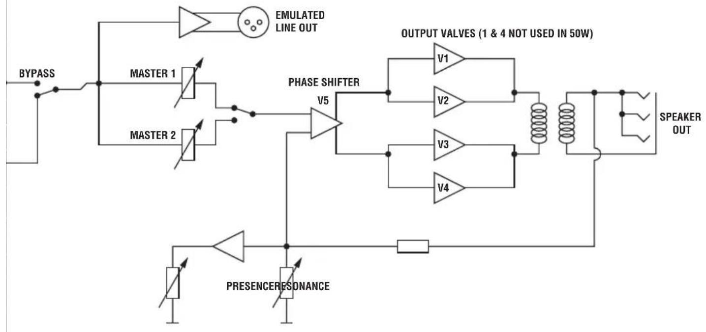
MASTER SECTION
The master volume controls set the overall volume of the amp across all channels. Master 1 and Master 2 can be assigned to any mode and can be switched back and forth.
5. MASTER 1
Master 1 is used on all channels/modes by default.
6. MASTER 2
To set a channel/mode to recall master 2, select the channel and mode, push the master button to engage master 2 and then switch out of the mode. When you re-visit the mode, the amp will automatically recall which master volume control you were previously using.
7. MASTER SWITCH
Switch between master 1 and master 2 for different volume settings on the same channel/ mode. The red led in the switch indicates that master 2 is engaged. The light is off when master 1 is engaged.
Note: pre-sets stored in the footswitch will recall whether master 1 or master 2 was selected.
However, it will not recall the previous level of the master volume control.
9. PRESENCE
Adjusts the high frequencies of the power amp. Increasing high frequencies adds more bite to your sound.
8. RESONANCE
Adjusts the low frequencies of the power amp. Increasing low frequencies adds more bottom end giving you a fatter sound.
Warning: care should be taken to avoid over exertion of the speaker cones in high resonance settings.
Note: both the presence and resonance controls are power amp controls and therefore only have effect when playing through a speaker.
15. INPUT JACK SOCKET
Connect your guitar here using a 1 / 4 " jack instrument cable.
REAR PANEL FUNCTIONS
1. POWER INLET
The supplied mains power lead is connected here. The mains input voltage rating that your amp has been built for is shown on the rear panel.
Warning: before powering on, ensure the amp is compatible with the mains voltage of the country that the amp is being used in. If you have any doubt, please get advice from a qualified person.
2. MAINS FUSE
Protects the amp and mains supply in the event of a fault. The correct value of mains fuse is specified on the rear panel.
3. MIDI THRU
A copy of the signal from the MIDI In connector is available on the MIDI thru socket to allow daisy chaining of MIDI equipment.
4. MIDI IN
Connect any external MIDI equipment to the MIDI In DIN socket.
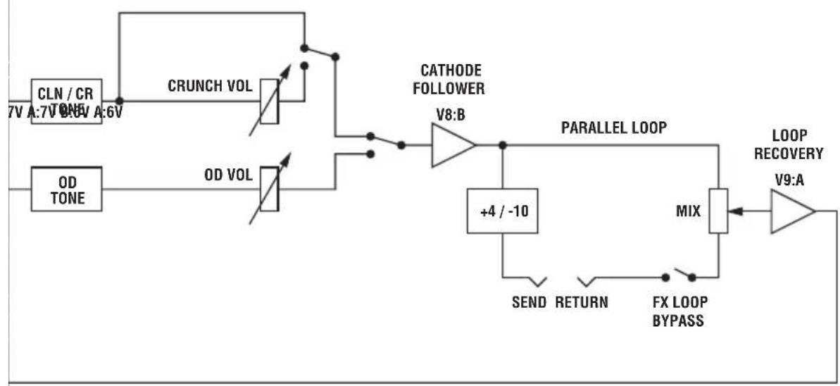
SERIES/PARALLEL FX LOOP
This is a programmable FX loop located after the pre-amp, right before the reverb and series loop circuits. The FX Loop switch engages/disengages this effects loop.
13. SERIES/PARALLEL FX LOOP: SEND
Connect your external FX equipment here using a 14 " jack instrument cable.
12. SERIES/PARALLEL FX LOOP: RETURN
Return your signal from external FX equipment here using a 1 / 4 jack instrument cable.
11. SERIES/PARALLEL FX LOOP: FX LEVEL
Configure the loop for use with either professional equipment (+4dBu setting) or with guitar level effects like effects pedals (-10dBV setting).
10. SERIES/PARALLEL FX LOOP: MIX CONTROL
Control the amount of effect that can be dialled in with the mix control. When mix is set to wet, all the signal goes through the external loop, adding more direct (unprocessed) signal as you turn it towards dry.
POWER AMP INSERT/SERIES LOOP
This is a passive loop connected right before the master controls. It is a line level loop so it is recommended to only use high headroom devices to avoid signal degradation.
9. PRE-AMP OUT/SEND
Connect your external FX equipment here using a 14 " jack instrument cable.
8. POWER-AMP IN/RETURN
Return your signal from external FX equipment here using a 1/4^n jack instrument cable.
7. BYPASS SWITCH
Engage/disengage the power amp insert/series loop. This switch cannot be programmed.
6. EMULATED LINE OUT
This output sends signal to external equipment. The signal is taken pre-master volume, processed through a 4x12 speaker cabinet emulator and electronically balanced.
Note: using the line out does not omit the need for a load to be connected (unless the amp is in silent recording mode).
5. FOOTSWITCH
Connect the supplied footswitch using any standard 1 / 4 jack instrument lead.
Note: using any other type of footswitch rather than the one supplied will have no effect and will be ignored by the amp.
FOOTSWITCH
14. SPEAKER OUTPUTS
1/4" jack speaker outputs. They are labelled according to the corresponding cabinet setups:
- 1 × 16 Ohm: connect a 16 speaker cabinet.
- 1 × 8 Ohm / 2 × 16 Ohm: connect a single 8 guitar cabinet or two 16 cabinets.
- 1 × 4 Ohm / 2 × 8 Ohm: connect a single 4 guitar cabinet or two 8 guitar cabinets.
Warning: although the amp has five speaker outputs, never attempt to connect more speakers than rated. The safe combinations are listed above. Any other speaker configuration may stress or damage the amp.
2-channel JVM amps come supplied with a 4-way programmable footswitch which can be connected to the amp via any standard 14 " jack instrument cable.
Warning: the supplied footswitch lead is unscreened and not suitable for guitar.
The footswitch features 5 LEDs marked clean / crunch, OD, master, reverb & FX. The LEDs for each of the 2 channels are 3-coloured green, orange and red. These indicate which channel and mode is selected, alongside the status of master, reverb and FX loop.
Each of the individual footswitches has 2 modes of operation:
- Switch store mode: assign any of its 4 switches to instantly recall any front panel function (channel/mode; reverb on/off; master volume 1/2 and FX loop on/off).
Note: if a switch is assigned to select a channel, once is has been activated it can be used to scroll through the three modes, just like its respective front panel switch.
- Pre-set store mode: Each switch can be programmed to instantly call up a combination of JVM button options to form a pre-set. This allows you to recall complete channel setups in any order and combination.
As the switches can be programmed independently you can program a mixture of the above.
Note: all the settings are stored within your footswitch; this means it can be plugged into any JVM amp and all your footswitch settings can be instantly recalled.
PROGRAMMING THE FOOTSWITCH
To enter footswitch program mode, press the 'footswitch/MIDI program' button on the front panel once. The indicator light will illuminate.
This mode allows you to program the footswitch.
Note: when the front panel 'footswitch/MIDI program' switch is off, the footswitch will execute commands the moment the switch is pressed down. When the footswitch program mode is active, you can use the amp as normal with commands executed on release of the footswitch.
To store the current amp status/settings to a footswitch (pre-set store mode):
- Press the 'footswitch/MIDI program' button on the front panel to enter footswitch program mode (red LED).
- Press and hold the desired footswitch for about 3 seconds. The FX footswitch LED will flicker indicating that the pre-set has been stored.
To store a specific front panel function to a footswitch (switch store mode):
- Press the footswitch/MIDI program button on the front panel to enter footswitch program mode (red LED).
- Press and hold the desired footswitch. While holding the footswitch down, in less than 3 seconds, press the front panel switch you want to map. The FX footswitch LED will flicker a couple of times indicating that the switch has been mapped.
Note: the footswitch/MIDI program switch cannot be assigned to a footswitch.
The footswitch can be hot-swapped and synchronises itself with the amp after connection. Connect the footswitch lead to the footswitch side first and then connect it to the amp.
FOOTSWITCH RESET
Warning: once the memory is erased it cannot be recovered.
To reset the footswitch to the factory default status:
- Unplug the footswitch at any of the cable sides.
- Press and hold the switch #4 (right switch).
- Plug in the footswitch cord.
- Release the switch and the FX LED will start blinking.
- If you want to erase the footswitch memory press the switch #3. To keep the memory press either the #1 or #2 switch.
- Release the switch and the footswitch will synchronise with the amp.
The factory default is as follows:
FSW #1: clean/crunch mode;
FSW #2: overdrive mode;
FSW #3: master;
FSW #4: reverb.
AVENTISSEMENT! CONSIGNES DE SECURITE
13. CANAL CLEAN/CRUNCH
FSW #1: mode clean/crunch;
FSW#2:mode overdrive;
6. EMULATED LINE OUT
13. CANAL LIMPIO/CRUNCH
RED : V6:A, V7:A, GAIN ON, V7:B
OD
GREEN : V6:A, V7:A GAIN ON, V7:B
ORANGE : V6:A, V6:B, V7:A GAIN OFF, V7:B
RED : V6:A, V6:B, V7:A GAIN ON, V7:B
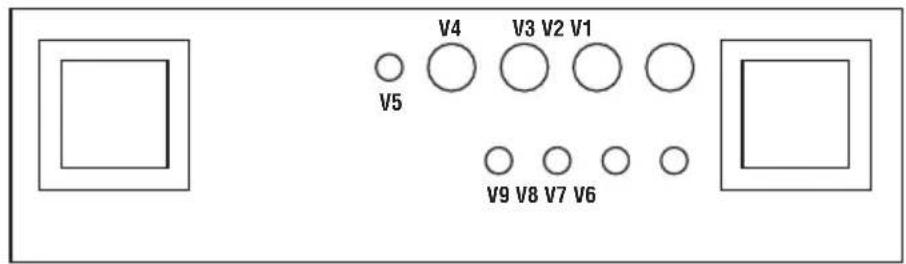
VALVE CHART
JVM205C / JVM210C / JVM215C
34561
2
7891611121314
YOUR SETTINGS
JVM205H / JVM210H

Valve Amplifier


FOOTWSWTCH/ MIDI PROGRAM

FX LOOP

MASTER 2

MASTER 1
MASTER

MASTER
RESONANCE

PRESENCE
JVM205C / JVM210C / JVM215C

INPUT

OVERDRIVE MODE


OVERDRIVE


CLEAN / CRUNCH


REVERB
RVB CLEAN / CRUNCH

RVB
0D

EAN/CRUNCH MODE
GAIN

VOLUME (Orange & Red)
TREBLE
MASTER

Whilst the information contained herein is correct at the time of publication, due to its policy of constant improvement and development, Marshall Amplification Plc reserves the right to alter specifications without prior notice.
MARSHALL AMPLIFICATION PLC, DENBIGH ROAD, BLETCHLEY, MILTON KEYNES, MK1 1DQ, ENGLAND.
T: +44 [0] 1908 375411
MARSHALL AMPLIFICATION PLC
REGISTERED IN ENGLAND
REGISTERED NUMBER: 805676
M3311.395 | CATS-00259-03
MARSHALL.COM
- QUICK START GUIDE
- WARNING! SAFETY INSTRUCTIONS
- MAINS INPUT & FUSE
- IMPORTANT SET UP INFORMATION
- Using your amp with speaker cabs
- Using your amp for silent recording
- TRANSPORTING YOUR EQUIPMENT
- FCC COMPLIANCE STATEMENT
- SPECIFICATION
- FRONT PANEL FUNCTIONS
- POWER SWITCH
- STANDBY SWITCH
- FOOTSWITCH/MIDI PROGRAM SWITCH
- FX LOOP SWITCH
- CHANNEL SECTION
- CLEAN/CRUNCH CHANNEL
- OVERDRIVE CHANNEL
- REVERB SECTION
- REVERB SWITCH
- REVERB CONTROL [OVERDRIVE CHANNEL]
- REVERB CONTROL (CLEAN/CRUNCH CHANNEL)
- MASTER SECTION
- MASTER 1
- MASTER 2
- MASTER SWITCH
- PRESENCE
- RESONANCE
- INPUT JACK SOCKET
- REAR PANEL FUNCTIONS
- POWER INLET
- MAINS FUSE
- MIDI THRU
- MIDI IN
- SERIES/PARALLEL FX LOOP
- SERIES/PARALLEL FX LOOP: SEND
- SERIES/PARALLEL FX LOOP: RETURN
- SERIES/PARALLEL FX LOOP: FX LEVEL
- SERIES/PARALLEL FX LOOP: MIX CONTROL
- POWER AMP INSERT/SERIES LOOP
- PRE-AMP OUT/SEND
- POWER-AMP IN/RETURN
- BYPASS SWITCH
- EMULATED LINE OUT
- FOOTSWITCH
- FOOTSWITCH
- SPEAKER OUTPUTS
- PROGRAMMING THE FOOTSWITCH
- FOOTSWITCH RESET
- AVENTISSEMENT! CONSIGNES DE SECURITE
- CANAL CLEAN/CRUNCH
- CANAL LIMPIO/CRUNCH
- YOUR SETTINGS
- MASTER
Brand : MARSHALL
Model : JVM215C
Category : Receiver