BFB 600K1AM - Camera Kern - Free user manual and instructions
Find the device manual for free BFB 600K1AM Kern in PDF.

User questions about BFB 600K1AM Kern
0 question about this device. Answer the ones you know or ask your own.
Ask a new question about this device
Download the instructions for your Camera in PDF format for free! Find your manual BFB 600K1AM - Kern and take your electronic device back in hand. On this page are published all the documents necessary for the use of your device. BFB 600K1AM by Kern.
USER MANUAL BFB 600K1AM Kern
Further language versions you will find online under www.kern-sohn.com/manuals
①
text_image
Technical diagram showing exploded and assembled views of a device with numbered componentstext_image
[K1] [K2]7 Betrieb
7.1 Einschalten
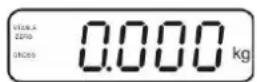
HEADER2: NT=NET, GS=GROSS
text_image
E+ Sent+ Sen- E- SH S+ S-
flowchart
graph TD
    A["LOAD CELL"] --> B["EXC+"]
    A --> C["SEN+"]
    A --> D["EXC-"]
    A --> E["SIG+"]
    A --> F["SIG-"]
    A --> G["SEN-"]
    H["SHIELD"] --> I["7"]
    H --> J["6"]
    H --> K["3"]
    H --> L["2"]
    H --> M["5"]
    H --> N["4"]
    H --> O["1"]
| PIN | Lastzelle | 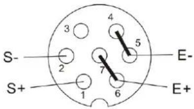 | |
| 6-Leiter | 4-Leiter | ||
| 7 | EXC+ | EXC+ | |
| 6 | SEN+ | ||
| 5 | EXC- | EXC- | |
| 4 | SEN- | ||
| 3 | SHIELD | SHIELD | |
| 2 | SIG- | SIG- | |
| 1 | SIG+ | SIG+ | |
text_image
Technical drawing of a mechanical bracket with detailed dimensions and sectional views3.4 Monitoring of Test Resources 11
4 Basic Safety Precautions.... 11
4.1 Pay attention to the instructions in the Operation Manual.... 11
4.2 Personnel training....11
5 Transport and storage.... 11
5.1 Testing upon acceptance 11
5.2 Packaging / return transport 11
6 Unpacking and placing.... 12
6.1 Installation Site, Location of Use 12
6.2 Unpacking and placing 12
6.3 Scope of delivery / serial accessories: 12
6.4 Transportation lock (illustration example).... 13
6.5 Error message 13
6.6 Mains connection.... 14
6.7 Storage battery operation (optional) 14
6.8 Adjustment.... 15
6.8.1 Verified weighing systems.... 15
6.8.2 Non verifiable weighing systems 18
6.9 Linearization 19
6.9.1 Verified weighing systems: 19
6.9.2 Non-verified weighing systems.... 20
6.10 Verification....21
7 Operation.... 24
7.1 Start-up 24
7.2 Switching Off 24
7.3 Zeroing 24
7.4 Simple weighing 24
7.5 Switch-over weighing unit (only not verifiable weighing systems) 25
7.6 Weighing with tare 26
7.7 Weighing with tolerance range 27
7.7.1 Tolerance check for target weight 28
7.7.2 Tolerance check for target quantity 30
7.8 Manual totalizing....32
7.9 Automatic adding-up....34
7.10 Parts counting.... 35
7.11 Animal weighing 36
7.12 Lock keyboard 37
7.13 Display background illumination.... 37
7.14 Automatic switch-off function „AUTO OFF“ 38
8 Menu 39
8.1 Overview non verifiable weighing systems (contacts of circuit board [K1] not short-circuited) 40
8.2 Overview verified weighing systems (contacts of circuit board [K1] short-circuited by means of jumper) 43
9 Service, maintenance, disposal...... 47
9.1 Clean 47
9.2 Service, maintenance 47
9.3 Disposal 47
9.4 Error messages 47
10 Data output RS 232C 49
10.1 Technical data 49
10.2 Printer mode / Printout examples (KERN YKB-01N) 50
10.3 Output log (continuous output) 52
10.4 Remote control instructions....52
10.5 I/O-Function....53
11 Instant help....54
12 Installing display unit / weighing bridge.... 55
12.1 Technical data 55
12.2 Weighing system design....55
12.3 How to connect the platform....56
12.4 Configure display unit 57
12.4.1 Verified weighing systems (contacts of circuit board [K1] short-circuited by means of jumper) 57
12.4.2 Non verifiable weighing systems (contacts of circuit board [K1] not short-circuited)...... 63
13 Annex....67
13.1 Dimensions Support base / wall bracket 67
14 Declaration of Conformity / Examination Certificate 68
1 Technical data
| KERN (Type) | KFB-TAM | KFN-TAM |
| Trademark | KFB-TM | KFN-TM |
| Display 5 1/2 - digit | ||
| Resolution (verified) 6000 | ||
| Single (Max.) 6.000 e | ||
| Dual (Max.) 3.000 e | ||
| Resolution (non-verified) | 30.000 | |
| Weighing ranges | 2 | |
| Divisions | 1,2,5,...10n | |
| Weighing Units | kg | |
| Functions | Weighing with tolerance range, Totalizing, Animal weighing | |
| Display | LCD 52 mm digits with back lighting | |
| DMS weighing cells | 80-100 Ω. Max. 4 item per 350 Ω; Sensitivity 2-3 mV/V | |
| Range calibration | We recommend ≥ 50 % max. | |
| Data output | RS232 | |
| Electric Supply | Input voltage 220 V – 240 V, 50 Hz | |
| Power pack secondary voltage 12V, 500mA | ||
| Housing | 250 x 160 x 58 | 266 x 165 x 96 |
| Admissible ambient temperature | 0°C – 40°C (non-verified)-10°C – 40°C (verified) | |
| Net weight | 1.5 kg | 2 kg |
| Rechargeable battery (optional) Operating / charge time | 35 h / 12 h | 90 h / 12 h |
| RS 232 interface | Standard | Option |
| Tripod | KERN BFS-07, option | |
| Support base incl. wall bracket | Standard | |
| IP protection | - | IP 67 as per DIN 60529 (rechargeable battery operation only) |
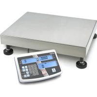
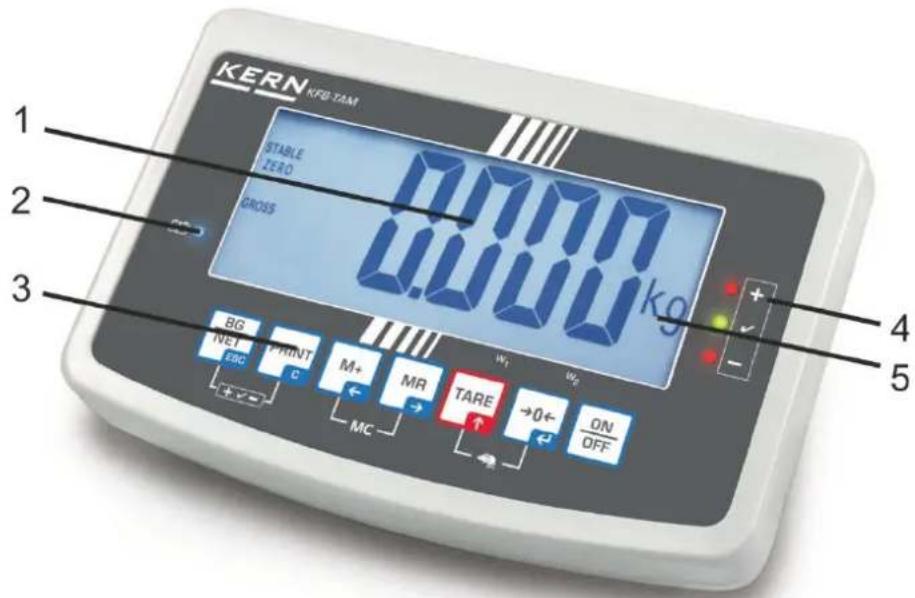
2 Appliance overview KFB-TAM: Synthetic finish
text_image
KERN KFB-TAM 1 2 3 0.000 kg STABLE ZERO GROSS BG NET ESC PRINT C M+ MC MR TARE +0← ON OFF 4 5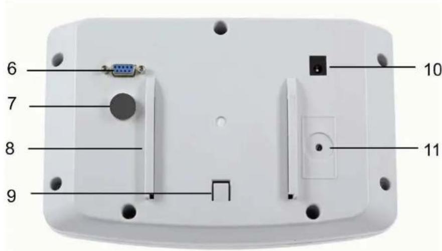
text_image
6 7 8 9 10 11- Status of rechargeable battery
- Keyboard
- Weight display
- Tolerance margin, see chap. 7.7
- Weighing unit
- RS-232
- Input connection load cell cable
- Guide rail support base / stand
- End stop support base / stand
- Mains adapter connection
- Adjustment switch
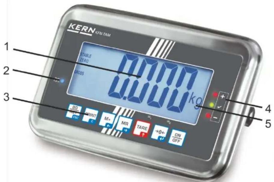
KFN-TAM: Stainless steel finish
text_image
KERN KFN TAM 1 STABLE ZERO GROSS 7.0000 kg 3 BG PRINT M+ MR TARE +0← ON OFF ESC C 4 5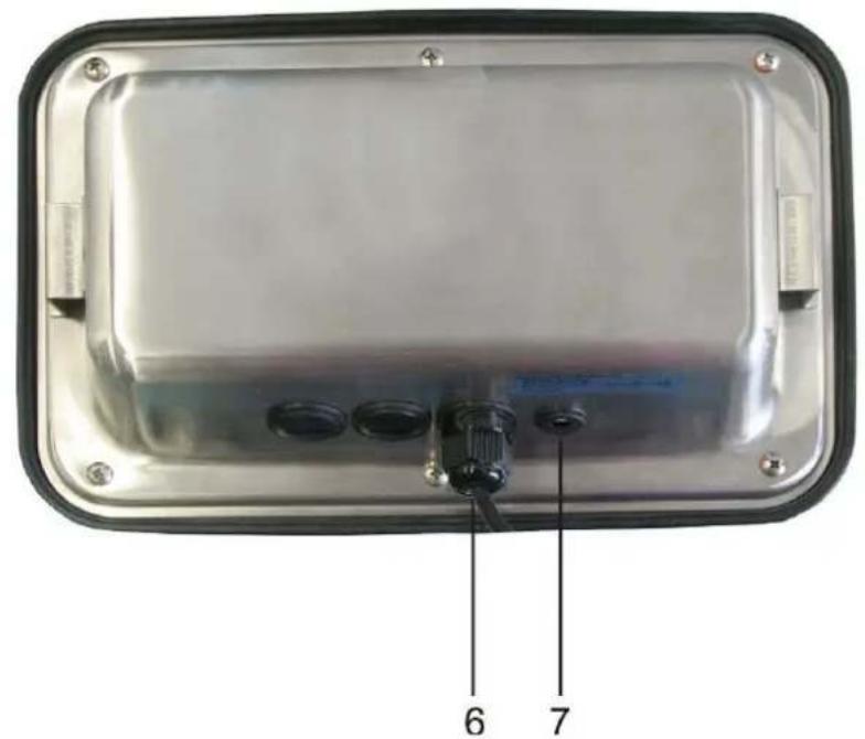
text_image
6 7- Status of rechargeable battery
- Keyboard
- Weight display
- For tolerance mark see chap. 7.7
- Weighing unit
- Input connection load cell cable
- Mains adapter connection
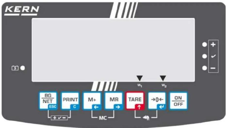
2.1 Keyboard overview
| Key Function | |
 | Turn on/off |
 Navigation button← Navigation button← | ZeroingConfirm entry |
 Navigation key ↑ Navigation key ↑ | TaringAt numeric input increase flashing digitScroll forward in menu |
 Navigation key → Navigation key → | Display sum totalDigit selection to the right |
 Navigation key ← Navigation key ← | Add weighing value to summation memoryDigit selection to the left |
 C C | Calculate weighing data via interfaceDelete |
 ESC ESC | Change between gross ⇔ and net weightBack to menu/weighing mode |
 | Call up animal weighing function |
 | Call up weighing with tolerance range |
 | Delete total added memory |
2.1.1 Numerical input via the navigation buttons
⇒ Press 0 and current setting will be displayed. The first digit will be flashing and is ready for changing.
⇒ If you do not wish to change the first digit, press Ⓜ and the second digit will start flashing.
Each time you press, the display will move to the subsequent digit, after the last digit the display will return to the first digit.
⇒ To change the selected (flashing) digit, press TARE repeatedly until the desired value is displayed. Then press M+ to access further digits and change them by TARE.
⇒ Complete your entry by →0←
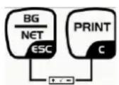
2.2 Overview of display
flowchart
graph TD
    A["BG/NET"] --> B["ESC"]
    C["PRINT"] --> D["C"]
    E["M+"] --> F["MC"]
    G["MR"] --> H["→"]
    I["TARE"] --> J["↑"]
    K["→0←"] --> L["←"]
    M["ON/OFF"] --> N["OFF"]
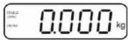
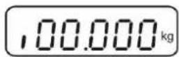
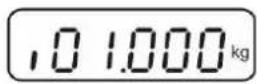
| Display Significance | |
 | Weighing range 1 |
 | Weighing range 2 |
 | Battery very low |
| STABLE Stability display | |
| ZERO Zero indicator | |
| GROSS Gross weight | |
| NET Net weight | |
| AUTO | Automatic add-up enabled |
| Kg Weighing unit | |
| M+ Totalisation | |
| LED + / √/ - | Indicators for weighing with tolerance range |
3 Basic Information (General)
3.1 Proper use
The display unit acquired by you is used in combination with a weighing plate and serves to determine the weighing value of material to be weighed. It is intended to be used as a “non-automatic weighing system”, i.e. the material to be weighed is manually and carefully placed in the centre of the weighing plate. As soon as a stable weighing value is reached the weighing value can be read.
3.2 Improper Use
Do not use display unit for dynamic weighings. In the event that small quantities are removed or added to the material to be weighed, incorrect weighing results can be displayed due to the “stability compensation” in the display unit. (Example: Slowly draining fluids from a container on the balance.)
Do not leave permanent load on the weighing pan. This may damage the measuring system.
Impacts and overloading exceeding the stated maximum load (max) of the weighing plate, minus a possibly existing tare load, must be strictly avoided. Both, the weighing plate and the display unit may be damaged during this process.
Never operate display unit in explosive environment. The serial version is not explosion protected.
Changes to the display unit's design are not permitted. This may lead to incorrect weighing results, safety-related faults and destruction of the display unit.
The display unit may only be operated in accordance with the described default settings. Other areas of use must be released by KERN in writing.
3.3 Warranty
Warranty claims shall be voided in case
• Our conditions in the operation manual are ignored
- The appliance is used outside the described uses
• The appliance is modified or opened
- Mechanical damage or damage by media, liquids, natural wear and tear
- The appliance is improperly set up or incorrectly electrically connected
• The measuring system is overloaded
3.4 Monitoring of Test Resources
In the framework of quality assurance the measuring-related properties of the display unit and, if applicable, the testing weight, must be checked regularly. The responsible user must define a suitable interval as well as type and scope of this test. Information is available on KERN's home page (www.kern-sohn.com with regard to the monitoring of display units' test substances and the test weights required for this. In KERN's accredited DKD calibration laboratory test weights and display units may be calibrated (return to the national standard) fast and at moderate cost.
4 Basic Safety Precautions
4.1 Pay attention to the instructions in the Operation Manual

→ Carefully read this operation manual before setup and commissioning, even if you are already familiar with KERN balances.
4.2 Personnel training
The appliance may only be operated and maintained by trained personnel.
5 Transport and storage
5.1 Testing upon acceptance
When receiving the appliance, please check packaging immediately, and the appliance itself when unpacking for possible visible damage.
5.2 Packaging / return transport

→ Keep all parts of the original packaging for a possibly required return.
⇒ Only use original packaging for returning.
→ Prior to dispatch disconnect all cables and remove loose/mobile parts.
→ Reattach possibly supplied transport securing devices.
→ Secure all parts such as the glass wind screen, the weighing platform, power unit etc. against shifting and damage.
6 Unpacking and placing
6.1 Installation Site, Location of Use
The display units are designed in a way that reliable weighing results are achieved in common conditions of use.
Precise and fast work is achieved by selecting the right place for your display unit and your weighing plate.
On the installation site observe the following:
- Place the display unit and the weighing plate on a stable, even surface.
- Avoid extreme heat as well as temperature fluctuation caused by installing next to a radiator or in the direct sunlight;
- Protect the display unit and the weighing plate against direct draft from open windows or doors.
- Avoid jarring during weighing;
- Protect the display unit and the weighing plate against high humidity, vapours and dust.
- Do not expose the display unit to extreme dampness for longer periods of time. Non-permitted condensation (condensation of air humidity on the appliance) may occur if a cold appliance is taken to a considerably warmer environment. In this case, acclimatize the disconnected appliance for ca. 2 hours at room temperature.
- Avoid static charge of goods to be weighed or weighing container.
Major display deviations (incorrect weighing results) may be experienced should electromagnetic fields (e.g. due to mobile phones or radio equipment), static electricity accumulations or instable power supply occur. Change location or remove source of interference.
6.2 Unpacking and placing
Take the display unit carefully out of its packaging, remove the plastic jacket and install it at the designated work space.
Mount the display unit in a way that facilitates operation and where it is easy to see.
6.3 Scope of delivery / serial accessories:
- Display Unit
- Mains adapter
• Support base incl. wall bracket - Operating instructions
6.4 Transportation lock (illustration example)
Please note: if the display unit is used together with platform with transportation lock, this transportation lock must be released prior to use:
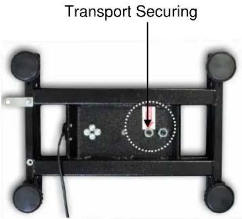
text_image
Transport Securing6.5 Error message

As soon as an error message appears in the balance display, the balance must not more be used, e.g. Err 4
6.6 Mains connection
Power is supplied via the external mains adapter. The stated voltage value must be the same as the local voltage.
Only use original KERN mains adapters. Using other makes requires consent by KERN.
6.7 Storage battery operation (optional)
Before the first use, the battery should be charged by connecting it to the mains power supply for at least 12 hours.
If the weight display shows, this is an indication that the capacity of the rechargeable battery is almost exhausted. The unit will be ready for operation for approx. another 10 hours before switching off automatically. Charge the battery with the help of the supplied power pack.
The LED display informs you during loading about the loading status of the rechargeable battery.
red: Voltage has dropped below prescribed minimum.
green: Battery is completely discharged
yellow: Charging storage battery
To conserve energy, enable the automatic switch-off function „AUTO OFF“, see chap. 7.14.
6.8 Adjustment
As the acceleration value due to gravity is not the same at every location on earth, each display unit with connected weighing plate must be coordinated - in compliance with the underlying physical weighing principle - to the existing acceleration due to gravity at its place of location (only if the weighing system has not already been adjusted to the location in the factory). This adjustment process must be carried out for the first commissioning, after each change of location as well as in case of fluctuating environment temperature. To receive accurate measuring values it is also recommended to adjust the display unit periodically in weighing operation.
i
- In weighing systems with a resolution of < 15 000 dividing steps an adjustment is recommended.
In weighing systems with a resolution of > 15 000 dividing steps a linearisation is recommended (see chap. 6.10). - Prepare the required adjustment weight. The weight to be used depends on the capacity of the scale. Carry out adjustment as near as possible to the scale's maximum weight. Info about test weights can be found on the Internet at: http://www.kern-sohn.com.
- Observe stable environmental conditions. Stabilisation requires a certain warm-up time.
6.8.1 Verified weighing systems
i
In verified weighing systems the menu item for adjustment „P2 mode“ is blocked.
KERN KFB-TAM
To disable the access lock, destroy the seal and actuate the adjustment switch. Position of the adjustment switch see chap. 6.11
KERN KFN-TAM
To override the blocked access you will have to destroy the seal before calling up the menu and to short-circuit the two contacts on the circuit board [K2], using a jumper (See chap. 6.11).
Attention:
After destruction of the seal the weighing system must be re-verified by an authorised agency and a new verification wire/seal mark fitted before it can be reused for applications subject to verification.
Call up menu:
| 1. Switch-on balance and during the selftest press |  |
2. Press  , [3KXX] subsequently, the first menu block „PO CHK“ will be displayed. , [3KXX] subsequently, the first menu block „PO CHK“ will be displayed. | 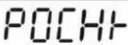 |
3. Press  repeatedly until „P2 mode“ will be displayed. For the KFB-TAM model operate the adjustment switch. repeatedly until „P2 mode“ will be displayed. For the KFB-TAM model operate the adjustment switch. |  |
4. Press  and select the set weighing scales type by and select the set weighing scales type by  . S,Gr = Single-range balance dURL 1 = Dual range balance dURL 2 = Multi-interval balance . S,Gr = Single-range balance dURL 1 = Dual range balance dURL 2 = Multi-interval balance |  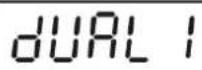 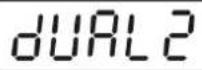 |
5. Acknowledge with  |  |
6. Press  repeatedly until „CAL“ will be displayed. repeatedly until „CAL“ will be displayed. |  |
7. Confirr  and select setting „noLin“ by and select setting „noLin“ by  |  |
How to carry out an adjustment:
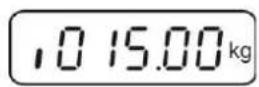
→ Confirm menu setting „noLin“ by  Ensure that there are no objects on the weighing plate. Ensure that there are no objects on the weighing plate. |   |
| → Wait for stability display, then press →0←. | 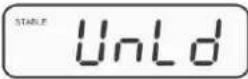 |
| → The currently set adjustment weight will be displayed. | 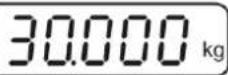 |
| → To change by using the navigation buttons (see chap. 2.1.1) select the desired setting, the active digit is flashing.→ Acknowledge with →0←. | 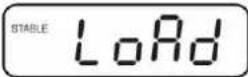 |
| → Carefully place adjusting weight in the centre of the weighing plate. Wait for stability display, then press →0←. | 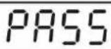 |
| → After the adjustment the balance will carry out a self-test.Remove adjusting weight during selftest, balance will return into weighing mode automatically.An adjusting error or incorrect adjusting weight will be indicated by the error message; repeat adjustment procedure. | 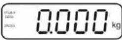 |
6.8.2 Non verifiable weighing systems
Call up menu:
- Switch-on balance and during the selftest press
- Press subsequently M+, BG NET ESC, TARE the first menu block "PO CHK" will be displayed.
- Press TARE repeatedly until „P3 CAL“ will be displayed.
- Confirm with →0←; press TARE repeatedly until „CAL“ appears.
- Acknowledge using +0 , the current setting is displayed.
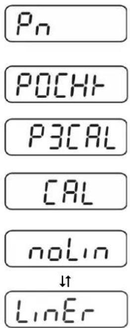
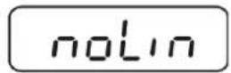
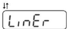
→ Press →0← to confirm; press TARE to select setting. noLin = adjustment LineAr = linearization, see chap. 6.10
text_image
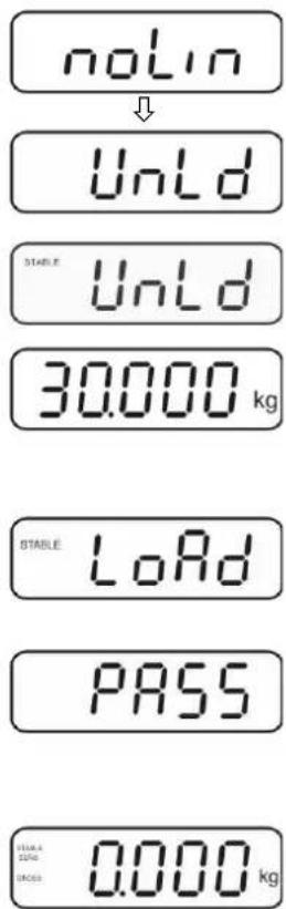
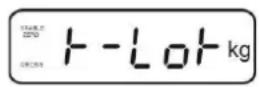
Pn POCHT P3CAL CAL noLin LinErHow to carry out adjustment:
→ Confirm menu setting „noLin“ by →0←. Ensure that there are no objects on the weighing plate.
→ Wait for stability display, then press →0←.
→ The currently set adjustment weight will be displayed.
⇒ To change by using the navigation buttons (see chap. 2.1.1) select the desired setting, the active digit is flashing.
→ Acknowledge with →0←
→ Carefully place adjusting weight in the centre of the weighing plate. Wait for stability display, then press →0←.
⇒ After the adjustment the balance will carry out a self-test. Remove adjusting weight during selftest, balance will return into weighing mode automatically. An adjusting error or incorrect adjusting weight will be indicated by the error message; repeat adjustment procedure.
text_image
no LIN ↓ UnLd STABLE UnLd 30.000 kg STABLE LoRd PASS 0.000 kg6.9 Linearization
Linearity shows the greatest deviation of a weight display on the scale to the value of the respective test weight according to plus and minus over the entire weighing range. If linearity deviation is discovered during a testing instrument control, you can improve this by means of linearization.

- In balances with a resolution of > 15 000 dividing steps carrying out a linearisation is recommended.
- Carrying out linearization is restricted to specialist staff possessing well acquainted with the workings of weighing scales.
- The test weights to be used must be adapted to the weighing scale's specifications; see chapter "testing instruments control".
- Observe stable environmental conditions. Stabilisation requires a certain warm-up time.
- After successful linearisation you will have to carry out calibration; see chapter “testing instruments control”.
- The adjustment is locked for verified balances. To disable the access lock, destroy the seal and actuate the adjustment switch. Position of the adjustment switch see chap. 6.11
6.9.1 Verified weighing systems:
⇒ Menu item P2 mode⇒Cal⇒Call up liner, see chap. 6.9.1
⇒ Confirm by 0 , the password query „Pn“ will be displayed.
⇒ Press subsequently , +ESC , or , 0 , . Ensure that there are no objects on the weighing pan.
→ Wait for stability display, then press →0←
When "Ld 1" is displayed, put the first adjustment weight (1/3 max) carefully in the centre of the weighing platform. Wait for stability display, then press
When "Ld 2" is displayed, put the second adjustment weight (2/3 max) carefully in the centre of the weighing platform. Wait for stability display, then press 0
When "Ld 3" is displayed, put the third adjustment weight (max) carefully in the centre of the weighing platform. Wait for stability display, then press 0


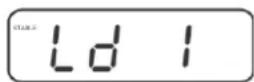


⇒ After linearisation the balance will carry out a self-test. Remove adjusting weight during selftest, balance will return into weighing mode automatically.
6.9.2 Non-verified weighing systems
⇒ Call-up menu item P3 CAL⇒Cal⇒Liner, see chap. 6.9.1
⇒ Confirm by 0 , the password query „Pn“ will be displayed.
⇒ Press , M+, MR or MR, 0 , PRINT c subsequently.
Ensure that there are no objects on the weighing pan.
→ Wait for stability display, then press →0←.
When "Ld 1" is displayed, put the first adjustment weight (1/3 max) carefully in the centre of the weighing platform. Wait for stability display, then press →0←
When "Ld 2" is displayed, put the second adjustment weight (2/3 max) carefully in the centre of the weighing platform.
Wait for stability display, then press →0←
When "Ld 3" is displayed, put the third adjustment weight (max) carefully in the centre of the weighing platform. Wait for stability display, then press 0
⇒ After a successful linearisation the balance will carry out a self-test. Remove adjusting weight during selftest, balance will return into weighing mode automatically.


6.10 Verification
General introduction:
According to EU directive 2014/31EU balances must be officially verified if they are used as follows (legally controlled area):
a) For commercial transactions if the price of goods is determined by weighing.
b) For the production of medicines in pharmacies as well as for analyses in the medical and pharmaceutical laboratory.
c) For official purpose.
d) For manufacturing final packages.
In cases of doubt, please contact your local trade in standard.
Verification notes:
An EU Qualification Approval is in existence for verified weighing systems. If a balance is used where obligation to verify exists as described above, it must be verified and re-verified at regular intervals.
Reverification is carried out according to the relevant national statutory regulations.
The validity for verification of balances in Germany is e.g. 2 years.
The legal regulation of the country where the balance is used must be observed!

- Verification of the weighing system is invalid without the "seal".
Notes on verified weighing systems
KFB-TAM:
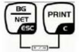
Access to conductor plate:
- Remove seal
- Open display unit
- The application of the display unit as a weighing system able to be verified requires that the contacts of the circuit board are short-circuited with the help of a jumper [K1].
For non verifiable weighing systems remove the jumper.
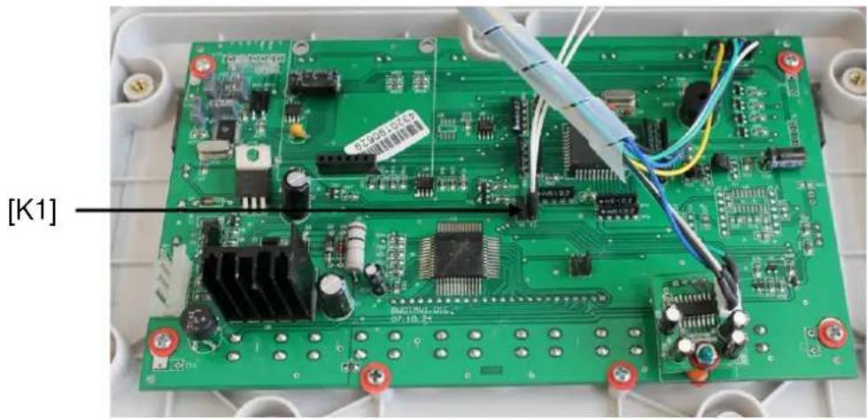
text_image
[K1]In verified weighing systems the menu item for adjustment, „P2 mode“ will be blocked.
To disable the access lock, destroy the seal and actuate the adjustment switch.
Position of seals and adjusting switch
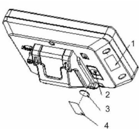
text_image
Technical diagram of a device housing with numbered components labeled 1 to 4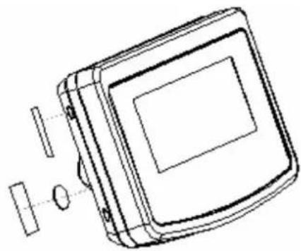
natural_image
Technical line drawing of a square electronic device with internal components and mounting holes (no text or symbols)- Self-destroying seal mark
- Adjustment switch
- Cover of adjustment switch
- Self-destroying seal mark
KFN-TAM:
Access to conductor plate:
- Remove seal
- Open display unit
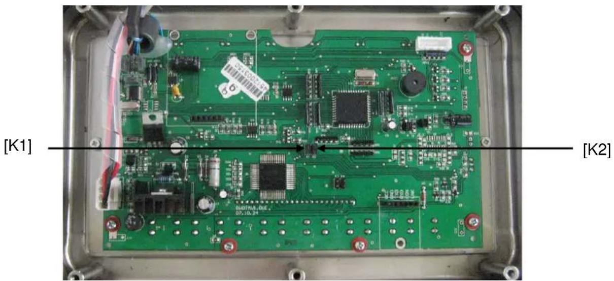
- The application of the display unit as a weighing system able to be verified requires that the contacts of the circuit board are short-circuited with the help of a jumper [K1]. For non verifiable weighing systems remove the jumper.
• To adjust, short-circuit the contacts of the circuit board, using a jumper [K2].
text_image
[K1] [K2]7 Operation
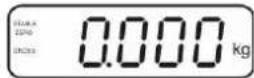
7.1 Start-up
⇒ Press and the instrument will carry out a self-test. As soon as the weight display appears, the instrument will be ready to weigh.
7.2 Switching Off
⇒ Press and the display will disappear.
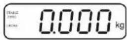
7.3 Zeroing
Resetting to zero corrects the influence of light soiling on the weighing plate. The unit is equipped with an automatic zero setting function. Therefore the unit can be reset to zero at any time as follows:
→ To unload the weighing system
⇒ Press and zero display as well as indicator ZERO will appear.
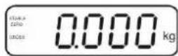
7.4 Simple weighing
→ Place goods to be weighed on balance.
→ Wait until stability display STABLE appears.
→ Read weighing result.
Overload warning
Overloading exceeding the stated maximum load (max) of the device, minus a possibly existing tare load, must be strictly avoided. This could damage the instrument.
Exceeding maximum load is indicated by the display of „----“ and an audio sound. Unload weighing system or reduce preload.
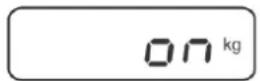
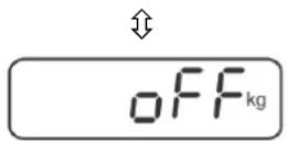
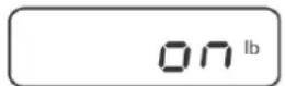
7.5 Switch-over weighing unit (only not verifiable weighing systems)
How to enable weighing units:
→ Call-up menu item P5 Unt, see chap. 8.1
⇒ Press 0 and the first weighing unit with the current setting will be displayed.
⇒ To enable [on] / disable [off] the displayed weighing unit, press TARE
⇒ Acknowledge with →0←. The next unit with the current setting will be displayed.
⇒ To enable [off] / disable [on] the displayed weighing unit, press TARE
⇒ Acknowledge with 0
Repeat sequence for each weighing unit. Note: „tj“ and „Hj“ cannot be activated at the same time, only either ... or ... .
→ Return to weighing mode using ESC
Switch-over weighing unit:
Keep pressed, the display changes over to the weighing units activated before (e.g. kg lb)

7.6 Weighing with tare
⇒ Deposit weighing vessel. After successful standstill control press the button. Zero display and indicator NET appear.
text_image
STABLE DOWG NET 0.000 kgThe weight of the container is now internally saved.
→ Weigh the material, the net weight will be indicated.
→ The weight of the weighing container will be displayed as a minus number after removing the weighing container.
⇒ The tare procedure can be repeated as many times as necessary, for example with initial weighing of several components for a mix (add-on weighing). The limit is reached when the taring range capacity (see type plate) is full.
→ To change between gross weight and net weight, press CSC.
⇒ To delete the tare value, remove load from weighing plate and press TARE
7.7 Weighing with tolerance range
You can set an upper or lower limit when weighing with tolerance range and thus ensure that the weighed load remains exactly within the set limits.
During tolerance tests such as dosing, portioning and sorting the unit will indicate exceeded or undershot limits by emitting an optical or acoustic signal.
Audio signal:
The acoustic signal depends on the settings in menu block „BEEP“.
Options:
- no Acoustic signal turned off
- ok An acoustic signal sounds when load is within tolerance limits
- ng An acoustic signal sounds when load is beyond tolerance limits
Optical signal:
Three colour signal lights indicate whether the load is within the two tolerance limits. The signal lights provide the following information:
 | + | Goods to be weighed above tolerance limit | Red signal light glowing |
| √ | Goods to be weighed within tolerance range | Green signal light glowing | |
| - | Goods to be weighed below tolerance limit | Red signal light glowing |
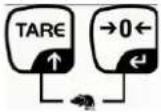
The settings for tolerance weighing may be called up either via menu block „P0 CHK“ (see chap. 8) or faster via the key combination
7.7.1 Tolerance check for target weight
Settings
⇒ Press and at the same time in weighing mode.
↓

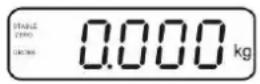
⇒ Press TARE until the display for entering the lower limit value nETL appears.

⇒ Press →0←, the current setting will be displayed.
To enter the lower limit, e. g. 1000 Kg, press the navigation keys (See chap. 2.1.1); the currently enabled digit will be flashing.
→ Confirm input by →0←

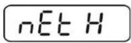
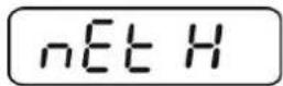
⇒ Press TARE repeatedly until nE t H is displayed.
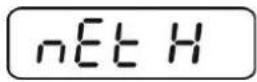
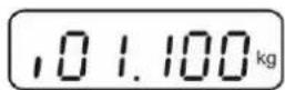
⇒ Press 0 , the current setting for the upper limit will be displayed.
⇒ Press the navigation keys (See chap. 2.1.1) to enter the upper limit, e.g. 1,100 kg; the currently enabled digit will be flashing.
→ Confirm input by
⇒ Press TARE repeatedly until BEEP is displayed.

⇒ Press 0 and the current setting for the acoustic signal will be shown.

⇒ Select desired setting (no, ok, ng) by TARE ↑.

→ Confirm input by
⇒ Press ; weighing system is in tolerance weighing mode. From here evaluation takes place whether the goods to be weighed are within the two tolerance limits.
Weighing with tolerance range
⇒ Tare when using a weighing container.
→ Put on goods to be weighed, tolerance control is started. The signal lights indicate whether the load is within the two set limits.
| Load below specified tolerance | Load within specified tolerance | Load exceeds specified tolerance |
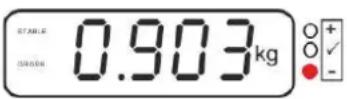 Red signal light next to „-“ ON illuminated Red signal light next to „-“ ON illuminated | 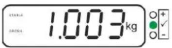 Green signal light next to „√, illuminated Green signal light next to „√, illuminated | 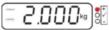 Red signal light next to „+“ ON illuminated Red signal light next to „+“ ON illuminated |

- The tolerance control is not active when the weight is under 20d.
• To delete limits, enter "00.000 kg".
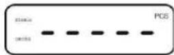
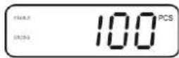
7.7.2 Tolerance check for target quantity
Settings
⇒ Press and at the same time in weighing mode.
↓

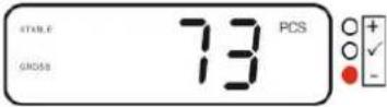
⇒ Press TARE until the display for entering the lower limit value PCSL appears.


→ Press →0←, the current setting will be displayed.
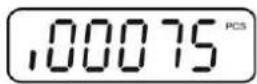

To enter the lower limit, e. g. 75 items, press the navigation buttons (see chap. 2.1.1); the currently enabled digit will be flashing.

→ Confirm input by 0
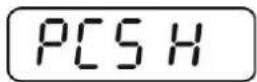
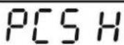
⇒ Press TARE repeatedly until PCSH is displayed.
⇒ Press 0 , the current setting for the upper limit will be displayed.
To enter the upper limit, e. g. 100 items, press the navigation buttons (see chap. 2.1.1); the currently enabled digit will be flashing.
→ Confirm input by

⇒ Press TARE repeatedly until BEEP is displayed.


→ 0← Press and the current setting for the acoustic signal will be shown.
⇒ Select desired setting (no, ok, ng) by TARE ↑.

→ Confirm input by
⇒ Press ; weighing system is in tolerance weighing mode. From here evaluation takes place whether the goods to be weighed are within the two tolerance limits.

Weighing with tolerance range
→ Set item weight, see chap. 7.10.
→ Tare when using a weighing container.
⇒ Put on goods to be weighed, tolerance control is started. The signal lights indicate whether the load is within the two set limits.
| Load below specified tolerance | Load within specified tolerance | Load exceeds specified tolerance |
 Red signal light next to „-“ ON illuminated Red signal light next to „-“ ON illuminated | 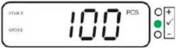 Green signal light next to „√, illuminated Green signal light next to „√, illuminated | 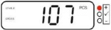 Red signal light next to „+“ ON illuminated Red signal light next to „+“ ON illuminated |

- The tolerance control is not active when the weight is under 20d.
• To delete limits, enter „00000 PCS“.
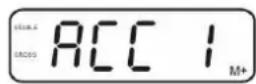
7.8 Manual totalizing
With this function the individual weighing values are added into the summation memory by pressing + and edited, when an optional printer is connected.

- Menu setting:
„P1 COM“ or „P2 COM“ ⇒ „MODE“ ⇒ „PR2“, see chap. 8 - The totalizing function is not active when the weight is under 20d.
Add up:
→ Place weighing goods A.
Wait until the stability display STABLE appears, then press M+. The weight value will be saved and printed if an optional printer is connected.
→ Remove the weighed good. More weighed goods can only be added when the display ≤ zero.
→ Place goods to be weighed B.
Wait until the stability display appears, then press M+. Weighing value will be added to summation memory and possibly printed. The number of weighing actions, followed by the total weight will be displayed for 2 sec.
→ Add more weighed goods as described before.
Please note that the weighing system must be unloaded between the individual weighing procedures.
→ This process may be repeated 99 times or till such time as the capacity of the weighing system has been exhausted.
Display and output sum „Total“:
⇒ Press MR →, number of weighing, followed by the total weight will be displayed for 2 sec. Press PRINT to print out this display.
Delete weighing data:
⇒ Press M+ and MR at the same time The data in the summation memory are deleted.
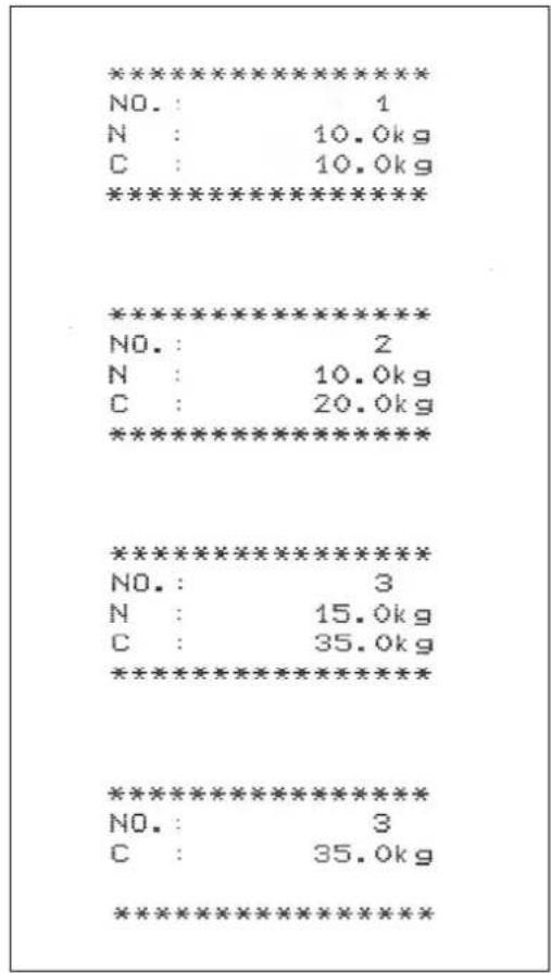
Printout example KERN YKB-01N:
Menu setting „P1 COM“ or „P2 COM“ ⇒ „Lab 2“ / Prt 7“
text_image
********************************************************************** NO.: 1 N : 10.0kg C : 10.0kg ********************************************************************** ********************************************************************** NO.: 2 N : 10.0kg C : 20.0kg ********************************************************************** ********************************************************************** NO.: 3 N : 15.0kg C : 35.0kg ********************************************************************** ********************************************************************** NO.: 3 C : 35.0kg **********************************************************************First weighing

Second weighing

Third weighing

A Number of weighings / total e


Additional printout example see chap. 10.2
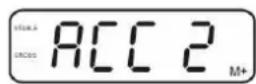
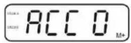
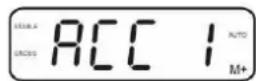
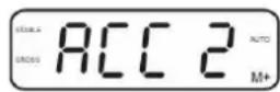
7.9 Automatic adding-up
With this function the individual weighing values are automatically added into the summation memory when the balance is unloaded without pressing + and edited, when an optional printer is connected.

- Menu settings:
→ Place weighing goods A.
After the standstill control sounds a signal tone. The weighing value will be added to the summation memory and printed.
→ Remove the weighed good. More weighed goods can only be added when the display ≤ zero.
⇒ Place goods to be weighed B.
After the standstill control sounds a signal tone. The weighing value will be added to the summation memory and printed. Number of weighing, followed by the total weight will be displayed for 2 sec.
→ Add more weighed goods as described before.
Please note that the weighing system must be unloaded between the individual weighing procedures.
→ This process may be repeated 99 times or till such time as the capacity of the weighing system has been exhausted.

Display and delete the weighing data, as well as printout examples see chap. 7.8.
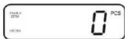
7.10 Parts counting
Before the balance can count parts, it must know the average part weight (i.e. reference). Proceed by putting on a certain number of the parts to be counted. The balance determines the total weight and divides it by the number of parts, the so-called reference quantity. Counting is then carried out on the basis of the calculated average piece weight.
As a rule:
The higher the reference quantity the higher the counting exactness.
In weighing mode MR press and hold until the message „P 10“ appears that is used to set the reference quantity.
↓
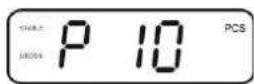
⇒ Use ↑ to set the desired reference quantity (such as 100), options include P 10, P 20, P 50, P100, P 200.
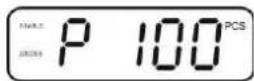
→ Place as many items to be counted (such as 100 items) as demanded by the set reference quantity and confirm by The weighing scales calculate the reference weight. The current quantity (such as 100 items) will be displayed.
↓
→ Remove reference weight. The balance is from now in parts counting mode counting all units on the weighing plate.
→ Back to Weighing mode by

7.11 Animal weighing
The animal weighing function is suitable for weighing restless loads.
The weighing system will display a mean value derived from several weighing results.
The animal weighing program can be enabled by either calling up menu block
„P3 OTH“ or „P4 OTH“ ⇒ „ANM“ ⇒ „ON“ (See chap. 8) or faster via key combination.
The indicator shows HOLD as long as the animal weighing function remains enabled.
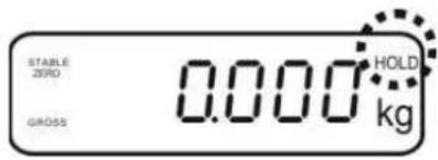
text_image
STABLE ZERO GROSS 0.000 HOLD kg→ Place the load on the weighing system and wait until the scale is steady.
⇒ Press ↑ and →0← at the same time; you will hear an acoustic signal, indicating that the animal weighing function is enabled.
Whilst averaging is taking place you can add or remove loads as the measuring value will be constantly updated.
⇒ To deactivate the animal weighing function press TARE and →0← at the same time.
7.12 Lock keyboard
To enable/disable the keyboard lock go to menu item „P3 OTH“ or „P4 OTH“ ⇒ „LOCK“, see chap.8.
Whilst the function is enabled the keyboard will self-lock after no key has been pressed for 10 minutes. „K-LCK“ will be displayed as soon as a key is pressed.
To disable the lock, press PRINT, MR and 0 hold plus (2 s) until „U LCK“ appears.
7.13 Display background illumination
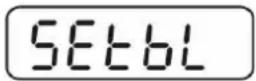
⇒ Keep 0 pressed (3s) until „setbl“ appears.

→ Press →0← again, the current setting will be displayed.
→ Use TARE to select the desired setting.
bl on Continuous background lighting
bl off Background illumination off
bl Auto Automatic background illumination on when weighing pate is loaded or key pressed.
⇒ Either save by 0 or cancel by pressing ESC. Back to weighing mode by ESC
7.14 Automatic switch-off function „AUTO OFF“
The unit is automatically switched off within the preset time when the display unit or the weighing bridge are not operated.
⇒ Keep 0 pressed (3s) until „setbl“ appears.
→ Press TARE to call up AUTO OFF-function
⇒ Press 0 , the current setting will be displayed.
→ Use TARE to select the desired setting.
of 0 AUTO OFF - function disabled
of 3 Weighing system will be turned off after 3 min.
of 5 Weighing system will be turned off after 5 min.
of 15 Weighing system will be turned off after 15 min.
of 30 Weighing system will be turned off after 30 min.
⇒ Either save by 0 or cancel by pressing ESC. Back to weighing mode by ESC
8 Menu
The application of the display unit as a verified weighing system requires that you short-circuit the two contacts [K1] of the circuit board, using a jumper. To that effect, a menu for verified weighing systems is available. For menu layout see chap. 8.2. There is no jumper for weighing systems that cannot be verified. To that effect, a menu is available for weighing systems that cannot be verified, Menu layout see chap. 8.1
Navigation in the menu:
| Call up menu | Switch-on balance and during the selftest press. PressBGNETsubsequently, the first menu block „PO CHK“ will be displayed. PressBGNETsubsequently, the first menu block „PO CHK“ will be displayed. |
| Select menu block | With help ofTARE, the individual menu items can be selected one after the other. |
| Select setting | Confirm selected  ;singThe current setting will be displayed. ;singThe current setting will be displayed. |
| Change settings | To change to the available settings, press the navigations keys as described in chap. 2.1. |
| Acknowledge setting / exit the menu | Either save by pre cel by pressingBGNET cel by pressingBGNET |
| Return to weighing mode | PressBGNETrepeat |
8.1 Overview non verifiable weighing systems (contacts of circuit board [K1] not short-circuited)
| Menu blockMain menu | Menu item Submenu | Available settings / explanation | ||
| PO CHKWeighing with tolerance range, see chap. 7.7 | nEt H Upper | limit value „Tolerance check weighing“, input see chap. 7.7.1 | ||
| nEt LO | Lower limit value „Tolerance check weighing“, input see chap. 7.7.1 | |||
| PCS H | Upper limit value „Tolerance check counting“, input see chap. 7.7.2 | |||
| PCS L | Lower limit value „Tolerance check counting“, input see chap. 7.7.2 | |||
| BEEP no | Acoustic signal for weighing with tolerance range switched off | |||
| ok | Audio sound when load is within tolerance limits | |||
| nG | Audio sound when load is beyond tolerance limits | |||
| P1 REFZero point settings | A2n0 Automatic zero point correction (Autozero) by changing the display, digits selectable (0.5d, 1d, 2d, 4d) | |||
| 0AUto Zero setting rangeLoad range where the display after switching-on the balance is set to zero.Selectable 0, 2, 5, 10, 20, 30, 50, 100 % | ||||
| 0rAGE | Zero setting rangeLoad range where the display is set to zero by pressing. Selectable 0, 2, 4, 10, 20*, 50, 100%. | |||
| 0tArE | Automatic taring „on / off“, taring range adjustable in menu item „0Auto“. | |||
| SPEEd | Not documented | |||
| Zero | Zero point setting | |||
| P2 COMInterface parameter | MODE | CONT | S0 off | Continuous data output, selectable “send zero” yes / no |
| S0 on | ||||
| ST1 | One output for stable weighing value | |||
| STC | Continuous data output of stable weighing values | |||
| PR1 | Output after pressing | |||
| PR2AUTO* | Manual totalizing, see chap. 7.8.Press and the weighing value will be added to the summation memory and issued.For automatic add-up see chap. 7.9.This function is used to issue and add individual weighing values automatically to the summation memory on unloading of weighing scale. | |||
| ASK | For remote control commands, see chap. 10.4 | |||
| wirel | Not documented | |||
| BAUD | Available Baudrate: 600, 1200, 2400, 4800, 9600* | |||
| Pr | 7E1 | 7 bits, even parity | ||
| 7o1 | 7 bits, odd parity | |||
| 8n1* | 8 bits, no parity | |||
| PTYPE | tPUP* | Standard printer setting | ||
| LP50 | Not documented | |||
| Lab | Lab x | For data output format, see chap.8.2, tab. 1 (Factory settings LAb 2 / Prt 7) | ||
| Prt | Prt x | |||
| LAnG | eng* | Standard settings English | ||
| chn | ||||
| P3 CALConfigurationdatasee chap. 12.4 | COUNT | Display internal resolution | ||
| DECI | Position of the decimal dot | |||
| DUAL | Setting balance type, capacity (Max) and readability (d) | |||
| off | Single-range balance | |||
| R1 inc | Readability | |||
| R1 cap | Capacity | |||
| on | Dual range balance | |||
| R1 inc | Readability 1st weighing range | |||
| R1 cap | Capacity 1st weighing range | |||
 | ||||
| R2 inc | Readability 2nd weighing range | |||
| R2 cap | Capacity 2nd weighing range | |||
| CAL | noLin | For adjustment, see chap. 6.9.2 | ||
| Liner | For linearization, see chap. 6.10.2 | |||
| GrA | Not documented | |||
| P4 OTH | LOCK | on | Keyboard lock enabled, see chap. 7.11 | |
| off* | Keyboard lock disabled | |||
| ANM | on | Animal weighing enabled, see chap. 7.10 | ||
| off* | Animal weighing disabled | |||
| P5 UntSwitch-over weighing unit, see chap. 7.5 | kg | on* | ||
| off | ||||
| g | on | |||
| off* | ||||
| lb | on | |||
| off* | ||||
| oz | on | |||
| off* | ||||
| tJ | on | |||
| off | ||||
| HJ | on | |||
| off | ||||
| P6 xcl Not documented | ||||
| P7 rst | Useto reset balance settings to factory default. | |||
| P8 UsbUSB connector | on | USB connector(to send data via RS232 select the setting "USB off") | ||
| off | ||||
| P9 Ckm CK nt | Not documented CK P5 | |||
| CK of | ||||
Factory settings are marked by *.
8.2 Overview verified weighing systems
(contacts of circuit board [K1] short-circuited by means of jumper)
In verified weighing systems the access to „P2 mode and „P4 tAr“ is locked.
KERN KFB-TAM:
To disable the access lock, destroy the seal and actuate the adjustment switch. Position of the adjustment switch see chap. 6.11.
KERN KFN-TAM:
In order to unlock the access, the seal must be destroyed and both contacts of the printed circuit board [K2] must be short-circuited by a jumper, see chap. 6.11.
Attention:
After destruction of the seal the weighing system must be re-verified by an authorised agency and a new verification wire/seal mark fitted before it can be reused for applications subject to verification.
| Menu blockMain menu | Menu item Submenu | Available settings / explanation | ||
| PO CHKWeighing with tolerance range, see chap. 7.7 | nEt H | Upper limit value „Tolerance check weighing“, input see chap. 7.7.1 | ||
| nEt LO | Lower limit value „Tolerance check weighing“, input see chap. 7.7.1 | |||
| PCS H | Upper limit value „Tolerance check counting“, input see chap. 7.7.2 | |||
| PCS L | Lower limit value „Tolerance check counting“, input see chap. 7.7.2 | |||
| BEEP | no | Acoustic signal for weighing with tolerance range switched off | ||
| ok | Audio sound when load is within tolerance limits | |||
| ng | Audio sound when load is beyond tolerance limits | |||
| P1 COMInterface parameter | MODE | CONT | S0 off | Continuous data output, selectable “send zero” yes / no |
| S0 on | ||||
| ST1 | One output for stable weighing value | |||
| STC | Continuous data output of stable weighing values | |||
| PR1 | Output after pressing | |||
| PR2 | Manual totalizing, see chap. 7.8Press a + the weighing value will be added to the summation memory and issued. | |||
| AUTO | For automatic totalizing see chap. 7.9This function is used to issue and add individual weighing values automatically to the summation memory on unloading of weighing scale. | |||
| ASK | For remote control commands, see chap. 10.4 | |||
| wireless | Not documented | |||
| baud | Available Baudrate: 600, 1200, 2400, 4800, 9600 | |||
| Pr | 7E1 | 7 bits, even parity | ||
| 7o1 | 7 bits, odd parity | |||
| 8n1 | 8 bits, no parity | |||
| PtYPE | tPUP | Standard printer setting | ||
| LP50 | Not documented | |||
| Lab | Lab x | Details see following table 1(Factory settings LAb 2 / Prt 7) | ||
| Prt | Prt x | |||
| Lang | Eng* | Standard setting English | ||
| Chn | ||||
| P2 modeKonfigurations-daten | SiGr | Single-range balance | ||
| COUNT | Display internal resolution | |||
| DECI | Position of the decimal dot | |||
| Div. | Readability [d] / verification value[s] | |||
| CAP | Balance capacity [Max] | |||
| CAL | noLin | Adjustment, see chap. 6.9 | ||
| LinEr | Linearisation, see chap. 6.10 | |||
| GrA | Not documented | |||
| dUAL 1 | Dual range balanceBalance with two weighing ranges and different maximum load and weighing ranges and interval sizes but only one load-supporting pan, whereby each range extends from zero to the respective maximum capacity. When load is removed, weighing scales will remain in 2nd range. | |||
| COUNT | Display internal resolution | |||
| DECI | Position of the decimal dot | |||
| div. | div 1 | Readability [d] / verification value [e]1. weighing range | ||
| div 2 | Readability [d] / verification value [e]2. weighing range | |||
| CAP | CAP 1 | Weighing scale capacity [max]1. Weighing range | ||
| CAP 2 | Weighing scale capacity [max]2. Weighing range | |||
| CAL | noLin | Adjustment, see chap. 6.9 | ||
| LinEr | For linearization, see chap. 6.10 | |||
| GrA | Not documented | |||
| dUAL 2 | Multi-interval balanceWeighing scales with one weighing range subdivided into partial weighing ranges, each providing a different scale interval. The scale interval depends on the applied load and is automatically changed during loading and unloading. | |||
| COUNT | Display internal resolution | |||
| DECI | Position of the decimal dot | |||
| div. | div 1 | Readability [d] / verification value [e]1. weighing range | ||
| div 2 | Readability [d] / verification value [e]2. weighing range | |||
| CAP | CAP 1 | Weighing scale capacity [max]1. Weighing range | ||
| CAP 2 | Weighing scale capacity [max]2. Weighing range | |||
| CAL | noLin | Adjustment, see chap. 0 | ||
| LinEr | Linearisation, see chap. 6.10 | |||
| GrA | Not documented | |||
| P3 OTHs. Kap. 7.10 / 7.11 | LOCK | on | Keyboard lock enabled | |
| off | Keyboard lock disabled | |||
| ANM | on | Animal weighing enabled | ||
| off | Animal weighing disabled | |||
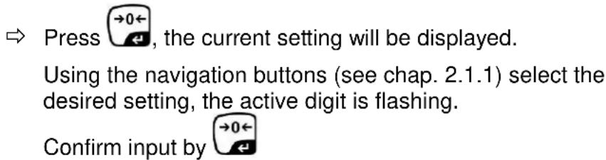
| P4 tArRestricted taringrange | Press  , the current setting will be displayed. Using the navigation buttons (see chap. 2.1.1) select the desired setting, the active digit is flashing.Confirm input by , the current setting will be displayed. Using the navigation buttons (see chap. 2.1.1) select the desired setting, the active digit is flashing.Confirm input by  | |||
| P5 StFollow up tare | St on | Follow up tare switched on | ||
| St off | Follow up tare switched off | |||
| P6 SP | 7.5, 15, 30 | Not documented | ||
Tab. 1.: Printout examples
- Menu setting P1 Com / P2 Com → Mode → PR2
- Data output

| LabPrt | 0 1 2 3 | |||
| 0~3 | **********GS: 5.000kg********** | **********NT: 5.000kgTW: 5.000kgGW: 10.000kg********** | **********GS: 5.000kgTOTAL: 10.000kg********** | **********NT: 5.000kgTW: 5.000kgGW: 10.000kgTOTAL: 10.000kg********** |
| 4~7 | **********No.: 1GS: 5.000kg********** | **********No.: 1NT: 5.000kgTW: 5.000kgGW: 10.000kg********** | **********No.: 1GS: 5.000kgTOTAL: 10.000kg********** | **********No.: 1NT: 5.000kgTW: 5.000kgGW: 10.000kgTOTAL: 10.000kg********** |
| G Gross weight | |
| N Net weight | |
| T Tare weight | |
| NO | Number weighing processes |
| C Total | of all individual weighings |
9 Service, maintenance, disposal
9.1 Clean
- Before cleaning, disconnect the appliance from the operating voltage.
- Do not use aggressive detergents (solvents or similar).
9.2 Service, maintenance
The appliance may only be opened by trained service technicians who are authorized by KERN.
Before opening, disconnect from power supply.
9.3 Disposal
Disposal of packaging and appliance must be carried out by operator according to valid national or regional law of the location where the appliance is used.
9.4 Error messages
| Error message | Description Possible causes | |
| - - - - - | Maximum load exceeded | ·Unload weighing system or reduce preload. |
| -- ol -- | ||
| Err 1 | Incorrect data input | ·Follow format “yy:mm:dd” |
| Err 2 | Incorrect time entry | ·Follow format “hh:mm:ss” |
| Err 4 Zeroing range exceeded due to switching-on balance or pressing (normally 4% max) | ·Object on the weighing plate·Overload when zeroing | |
| Err 5 Keyboard error | ||
| Err 6 | Value outside the A/D changer range | ·Weighing plate not installed·Damaged weighing cell·Damaged electronics |
| Err 9 Stability display does not appear | ·Check the environmental conditions. | |
| Err 10 Communication error | No data | |
| Err 15 Gravitation error | Range 0.9 ~ 1.0 | |
| Err 17 Taring range exceeded | Reduce load | |
| Err 19 Zero point displaced | Remedy:Adjust / linearize | |
| Fai I h /Fai II | Adjustment error | Repeat adjustment. |
| Err P | Printer error | Check communication parameters |
| Ba lo /Lo ba | Battery very low | Recharge battery |
Should other error messages occur, switch balance off and then on again. If the error message remains inform manufacturer.
10 Data output RS 232C
You can print weighing data automatically via the RS 232C interface or manually by pressing PRINT via the interface according to the setting in the menu.
This data exchange is asynchronous using ASCII - Code.
The following conditions must be met to provide successful communication between the weighing system and the printer.
- Use a suitable cable to connect the display unit to the interface of the printer. Faultless operation requires an adequate KERN interface cable.
- Communication parameters (baud rate, bits and parity) of display unit and printer must match. For a detailed description of interface parameters see chap. 8, menu block „P1 COM“ or „P2 COM“
10.1 Technical data
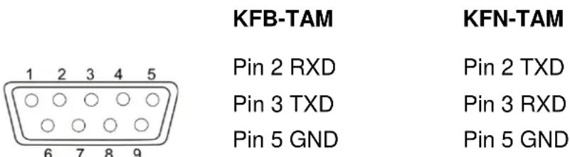
Connection 9 pin d-subminiature bushing
text_image
KFB-TAM 1 2 3 4 5 Pin 2 RXD Pin 3 TXD Pin 5 GND KFN-TAM Pin 2 TXD Pin 3 RXD Pin 5 GNDBaud rate Optional 600/1200/2400/4800/9600
Parity 8 bits, no parity / 7 bits, even parity / 7 bits, odd parity
10.2 Printer mode / Printout examples (KERN YKB-01N)

Menu setting P8 USB → off
- Weighing
- Continuous output
| ST | Stable value |
| US | Instable value |
| G | Gross weight |
| N | Net weight |
| T | Tare weight |
| NO | Number weighing processes |
| C | Total of all individual weighings |
| Space line |
10.3 Output log (continuous output)
- Weighing

text_image
HEADER 1 HEADER 2 -/L WEIGHT DATA k g CR LF WEIGHT UNIT TERMINATORHEADER1: ST=STABLE, US=UNSTABLE
HEADER2: NT=NET, GS=GROSS
10.4 Remote control instructions
| Command | Function | Printout examples |
| S Stable | weighing value for the weight is sent via the RS232 interface | ST,G, 1.000KG |
| W | Weighing value for the weight (stable or unstable) is sent via the RS232 interface | US,G, 1.342KGST,G, 1.000KG |
| T No data are sent, the balance carries out the tare function. | - | |
| Z | No data are sent, the zero-display appears. | - |
| P | Quantity will be sent via the RS232-interface | 10PCS |
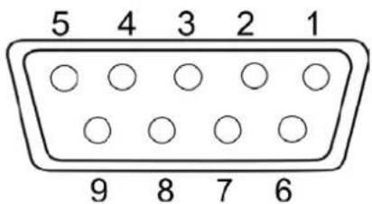
10.5 I/O-Function
Models KFB-TAM / KFN-TAM:
text_image
5 4 3 2 1 9 8 7 6| RS232 | KFB-TAM | KFN-TAM | |
| Pin 2 | RXD | TXD | |
| Pin 3 | TXD | RXD | |
| Pin 4 | VCC 5V | VCC 5V | |
| Pin 5 | GND | GND |
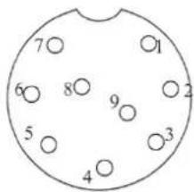
Model KFN-TAM:
text_image
7 6 8 9 2 5 3 4| Shift point | Pin 1 | VB | |
| Pin 5 | GND | ||
| Pin 6 | OK | ||
| Pin 7 | LOW | ||
| Pin 8 | HI | ||
| Pin 9 | BEEP |
11 Instant help
In case of an error in the program process, briefly turn off the display unit and disconnect from power supply. The weighing process must then be restarted from the beginning.
Help:
Fault Possible cause
The displayed weight does not glow.
• The display unit is not switched on.
- Mains power supply interrupted (mains cable defective).
• Power supply interrupted.
- (Rechargeable) batteries are inserted incorrectly or empty
- No (rechargeable) batteries inserted.
The displayed weight is permanently changing
- Draught/air movement
- Table/floor vibrations
- Weighing pan has contact with other objects.
- Electromagnetic fields / static charging (choose different location/switch off interfering device if possible)
The weighing result is obviously incorrect
• The display of the balance is not at zero
- Adjustment is no longer correct.
• Great fluctuations in temperature.
• Warm-up time was ignored.
- Electromagnetic fields / static charging (choose different location/switch off interfering device if possible)
Should other error messages occur, switch display unit off and then on again. If the error message remains inform manufacturer.
12 Installing display unit / weighing bridge
i Installation / configuration of a weighing system must be carried out by a well acquainted specialist with the workings of weighing balances.
12.1 Technical data
| Supply voltage: 5 V/150mA | |
| Max. signal voltage 0-10 mV | |
| Zeroing range 0-2 mV | |
| Sensitivity 2-3 mV/V | |
| Resistance parameter | 80 - 100 Ω, max 4 items per 350 Ω load cell |
12.2 Weighing system design
The display unit is suitable for connection to any analogue platform in compliance with the required specifications.
The following data must be established before selecting a weighing cell:
- Weighing balance capacity
This usually corresponds to the heaviest load to be weighed.
- Preload
This corresponds to the total weight of all parts that are to be placed on the weighing cell such as upper part of platform, weighing pan etc.
• Total zero setting range
This is composed of the start-up zero setting range ( ± 2%) and the zero setting range available to the user via the ZERO-key (2%). The total zero setting range equals therefore 4 % of the scale's capacity.
The addition of weighing scales capacity, preload and the total zero setting range give the required capacity for the weighing cell.
To avoid overloading of the weighing cell, include an additional safety margin.
- Smallest desired display division
• Verifiability, if required
The application of the display unit as a verified weighing system requires that you short-circuit the two contacts [K1] of the circuit board, using a jumper; for position see chap. 6.11.
Remove the jumper for weighing systems not able to be verified.
12.3 How to connect the platform
→ Disconnect the display unit from the power supply.
Solder the individual leads of the load cell cable onto the circuit board. See diagrams below.
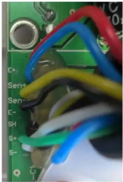
natural_image
Close-up of a green printed circuit board with multicolored wires wrapped around it (no visible text or symbols)
flowchart
graph TD
    A["LOAD CELL"] --> B["EXC+"]
    A --> C["SEN+"]
    A --> D["EXC-"]
    A --> E["SIG+"]
    A --> F["SIG-"]
    A --> G["SEN-"]
    H["SHIELD"] --> I["7"]
    H --> J["6"]
    H --> K["3"]
    H --> L["2"]
    H --> M["5"]
    H --> N["4"]
    H --> O["1"]
| PIN | Loadcell | 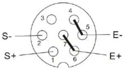 | |
| 6- conductor | 4- conductor | ||
| 7 | EXC+ | EXC+ | |
| 6 | SEN+ | ||
| 5 | EXC- | EXC- | |
| 4 | SEN- | ||
| 3 | SHIELD | SHIELD | |
| 2 | SIG- | SIG- | |
| 1 | SIG+ | SIG+ | |
12.4 Configure display unit
12.4.1 Verified weighing systems
(contacts of circuit board [K1] short-circuited by means of jumper)
For menu overview see chap. 8.2.
In verified weighing systems the menu item for calibration „P2 mode“ is blocked.
KERN KFB-TAM:
To disable the access lock, destroy the seal and actuate the adjustment switch. Position of the adjustment switch see chap. 6.11
KERN KFN-TAM:
To override the blocked access you will have to destroy the seal before calling up the menu and to short-circuit the two contacts on the circuit board [K2], using a jumper (See chap. 6.11).
Attention:
After destruction of the seal the weighing system must be re-verified by an authorised agency and a new verification wire/seal mark fitted before it can be reused for applications subject to verification.
| Call up menu:→ Switch-on balance and during the selftest pressPRINT. | |
| → PressBGNET, TAREsubsequently, the first menu block„PO CHK“ will be displayed. | POCH- |
| → PressTARErepeatedly until „P2 mode“ will be displayed.→ Operate the adjustment switch (models KFB-TAM). | P2nod |
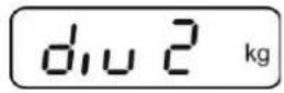
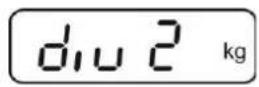
| → Press→0←and use→0←to select the weighing scales type.SiGrSingle-range balancedUAL1Dual range balancedUAL2Multi-interval balance | SiGr↓dUAL1↓dUAL2 |
| Example single range scales (d=10 g, max. 30 kg) | |
| → Confirm selected weighing scales type by pressing →the first menu item „COUNT“ will be shown. |  |
| 1. Display internal resolution→Press →0←, the internal resolution will be shown.→Return to menu by BG NET→Press →to select the next menu item. |    |
| 2. Position decimal point→Press →0←, the currently set position of the decimal dot is displayed.→Press →to select the desired setting. Options 0, 0.0, 0.00, 0.000, 0.0000. Confirm input by →0←→Press →to select the next menu item. | 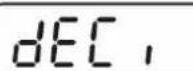  [kg] [kg]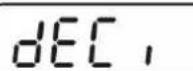 |
| 3. Readability→Press →0← and current setting will be displayed.Select desired setting by TARE↑Options 1, 2, 5, 10, 20, 50. Confirm entry by →0←→Press →to select the next menu item. |    |
4. Capacity
text_image
⇒ Press →0←, the current setting will be displayed. Using the navigation buttons (see chap. 2.1.1) select the desired setting, the active digit is flashing. Confirm input by →0←
text_image
⇒ Press TARE ↑ to select the next menu item.- Adjustment / linearization Adjustment or linearization is required after entering configuration data. For carrying out adjustment see chap. 6.9.1/step 6 or chap. 6.10.1 for linearisation


| Example dual range scales dURL (d = 2 / 5 g, max. 6 / 15 kg) | |
| → Confirm selected weighing scales type by →0←; the first menu item „COUNT“ will be shown. |  |
| 1. Display internal resolution→ Press →0←, the internal resolution will be shown.→ Return to menu by BG NET ESC→ Press TARE to select the next menu item. |    |
| 2. Position decimal point→ Press →0←, the currently set position of the decimal dot is displayed.→ Use TARE to select the desired setting. Options 0, 0.0, 0.00, 0.000, 0.0000.→ Confirm input by →0←→ Press TARE to select the next menu item. |    |
3. Readability
→ Press →0←, the display used to enter readability/verification value for first weighing range will appear.
⇒ Press →0←, the current setting will be displayed.
→ Select desired setting with TARE and acknowledge by →0←.
⇒ Press TARE to enter the next menu item for readability/verification value for second weighing range.
→ Press →0← and current setting will be displayed.
⇒ Select desired setting with TARE and acknowledge by →0←.
⇒ Press , the unit will return to the menu
→ Press TARE to select the next menu item.


4. Capacity
⇒ Press 0 and the display for entering the capacity for the first weighing range will appear.
→ Press →0← and current setting will be displayed.
→ Select desired setting with TARE and acknowledge by →0←.
→ Press TARE to select the next menu item used to enter the capacity for the second weighing range.
⇒ Press →0← and current setting will be displayed.
→ Select desired setting with TARE and acknowledge by →0←.
→ Press , the unit will return to the menu
→ Use TARE ↑ toselect next menu item.
- Adjustment / linearization Adjustment or linearization is required after entering configuration data. For carrying out adjustment see chap. 6.9.1/step 6 or chap. 6.10.1 for linearisation
⇒ Acknowledge using →0←, the current setting is displayed.
⇒ Acknowledge by 0 , select desired setting with TARE noLin = Adjustment LinEAR = Linearisation


12.4.2 Non verifiable weighing systems
(contacts of circuit board [K1] not short-circuited)
+ For menu overview see chap. 8.1.
| Call up menu Switch-on balance and during the selftest press . Press +, ESC, subsequently, the first menu block „PO CHK“ will be displayed. Press repeatedly until „CAL“ will be displayed. Press 0 , the first menu item „COUNT“ will be displayed. | |
| Navigation in the menu With help of , the individual menu items can be selected one after the other. Confirm selected menu item by pressing 0 . The current setting will be displayed. To change to the available settings, press the navigations keys as described in chap. 2.1.1. Either save by pressing 0 or cancel by pressing ESC . Press ESC repeatedly to exit menu. | |
| Parameter selection1. Display internal resolution⇒ Press →0←, the internal resolution will be shown.⇒ Return to menu byBGNETESC⇒ UseTAREto select another menu item. | ![Kern BFB 600K1AM - (contacts of circuit board [K1] not short-circuited) - 1](/content/2026/03/522699/images/5e32fdb456888525bdf5492f809381ce6fa7df38760393d7ca5bd1c24c7e4499.jpg) ![Kern BFB 600K1AM - (contacts of circuit board [K1] not short-circuited) - 2](/content/2026/03/522699/images/104f328d1a53c4e35d212cb9ca501666af4b3c39e121f14429357b1b98d64d64.jpg) ![Kern BFB 600K1AM - (contacts of circuit board [K1] not short-circuited) - 3](/content/2026/03/522699/images/4da3a046dc95289beb02efa27f14ec3c6728812cbd33f2321783c5f38a605f27.jpg) |
| 2. Position decimal point⇒ Press →0←, the currently set position of the decimal dot is displayed.To make changes using the navigation keys (See chap. 2.1.1), select the desired setting. Options 0, 0.0, 0.00, 0.000, 0.0000.Confirm input by→0←⇒ UseTAREto select another menu item. | ![Kern BFB 600K1AM - (contacts of circuit board [K1] not short-circuited) - 4](/content/2026/03/522699/images/e401260a9aa86ca3c5f8d2a0f1c3c212e7006426f545bb14d6c18e84985ec79b.jpg) ![Kern BFB 600K1AM - (contacts of circuit board [K1] not short-circuited) - 5](/content/2026/03/522699/images/4f6c348a3a0b452199f835eb74cff69fd9ac33e448847adab1b5c712be88d82c.jpg) ![Kern BFB 600K1AM - (contacts of circuit board [K1] not short-circuited) - 6](/content/2026/03/522699/images/1b6e9c1af497e2ada8659af5a9a89bb26e7a42c83f5f732f8740a5f0b97ee5bc.jpg) |
| 3. Weighing scales type, capacity and readability⇒ Press →0←and current setting will be displayed.⇒ Select desired setting byTARE„off“ Single-range balance„on“ Dual range balance⇒ Press →0←to confirm, the display for entering readability (for dual range scales for the first weighing range) appears.⇒ Press →0←, the current setting will be displayed.⇒ Select desired setting withTAREand acknowledge by. | ![Kern BFB 600K1AM - (contacts of circuit board [K1] not short-circuited) - 7](/content/2026/03/522699/images/1c609f626d962ff0fffecda6ba259d9b1063f87292c6cfabde44434a42040001.jpg) ![Kern BFB 600K1AM - (contacts of circuit board [K1] not short-circuited) - 8](/content/2026/03/522699/images/2b1df9f5efe7065c4df4d5087290fba204717a3747977fb5c8f892c7a8668bae.jpg) ![Kern BFB 600K1AM - (contacts of circuit board [K1] not short-circuited) - 9](/content/2026/03/522699/images/fdfbb637bdb85ee865a662b440cc68adb0d83f0fc9f47f67779f381d36392e6e.jpg) ![Kern BFB 600K1AM - (contacts of circuit board [K1] not short-circuited) - 10](/content/2026/03/522699/images/be0c008721df53712179dacecfa54b0ee38c0b989bd4ee3125fb7936d4b4d55a.jpg) r lnc r lnc |
| ⇒ PressTARE, the display for entering capacity will appear (at dual range balance for the first range). | r ICAP |
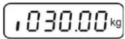
| ⇒ Press→0←, the current setting will be shown (such as max. = 2000kg). | 102000kg |
| ⇒ Using the navigation buttons (see chap. 2.1.1) select the desired setting, the active digit is flashing. | |
| ⇒ Acknowledge with→0←In a single-range balancethe entry of capacity / readability is finished. | r ICAP |
| either in single-range balance | |
| ⇒ PressBGNET, the unit will return to the menu PressTAREto call up next menu item „CAL“. | |
| or | |
| In a dual range balance enter readability/verification value and capacity of the second weighing range. | r2CAP |
| ⇒ PressBGNET, the display for entering the capacity of the second weighing range will appear. | 100000kg |
| ⇒ Press→0←, the current setting will be displayed. | |
| ⇒ Using the navigation buttons (see chap. 2.1.1) select the desired setting, the active digit is flashing. | |
| ⇒ Confirm input by→0← | |
| →Press ↑, the display for entering the readability of the second weighing range will appear.→Press →0←, the current setting will be displayed.→Select desired setting with ↑ and acknowledge by ↓.→Press BG NET ESC, the unit will return to the menu→Press ↑ to call next menu item. | ![Kern BFB 600K1AM - (contacts of circuit board [K1] not short-circuited) - 11](/content/2026/03/522699/images/e5ab526c3dd2f2c28dc5ee63f51845c7e8e99733c31516578c6d5f9e138c9b84.jpg) |
![Kern BFB 600K1AM - (contacts of circuit board [K1] not short-circuited) - 12](/content/2026/03/522699/images/36a61ab3205ff4f79744a75a88f1f7ac5c90a700056d2bdd8dc3de0d14bedefe.jpg) | |
![Kern BFB 600K1AM - (contacts of circuit board [K1] not short-circuited) - 13](/content/2026/03/522699/images/88734118aab5b31ed135df346168970fdf9dfb074de6dd111a4aa54dc3d3424f.jpg) | |
![Kern BFB 600K1AM - (contacts of circuit board [K1] not short-circuited) - 14](/content/2026/03/522699/images/c458d3ac565942de796855b3e5edb55834a5994935bccc5ccaaf03fa2d6f2215.jpg) | |
| 4. Adjustment or linearisationAdjustment or linearisation is required after entering configuration data.For carrying out adjustment see chap. 6.9.2/step 4 or chap. 6.10.2 for linearisation→Acknowledge using →0←, the current setting is displayed.→Press →0← to confirm, press ↑ to select the desired setting noLin = Adjustment LineAr = Linearisation | ![Kern BFB 600K1AM - (contacts of circuit board [K1] not short-circuited) - 15](/content/2026/03/522699/images/41048478b2fc36a712844b7ef4a419715ae3d9bd80b543632cc9e2a3b3441a5c.jpg) |
![Kern BFB 600K1AM - (contacts of circuit board [K1] not short-circuited) - 16](/content/2026/03/522699/images/1fe2327d3115e38306ae2d718c4b84bb252d9534c2e73f0d3299e74018af076f.jpg) ↓↑ ↓↑ ![Kern BFB 600K1AM - (contacts of circuit board [K1] not short-circuited) - 17](/content/2026/03/522699/images/a55f2e8e10314d5aa03e53103b0d718beb926baf719134ee3bf83062f5e5e0d7.jpg) |
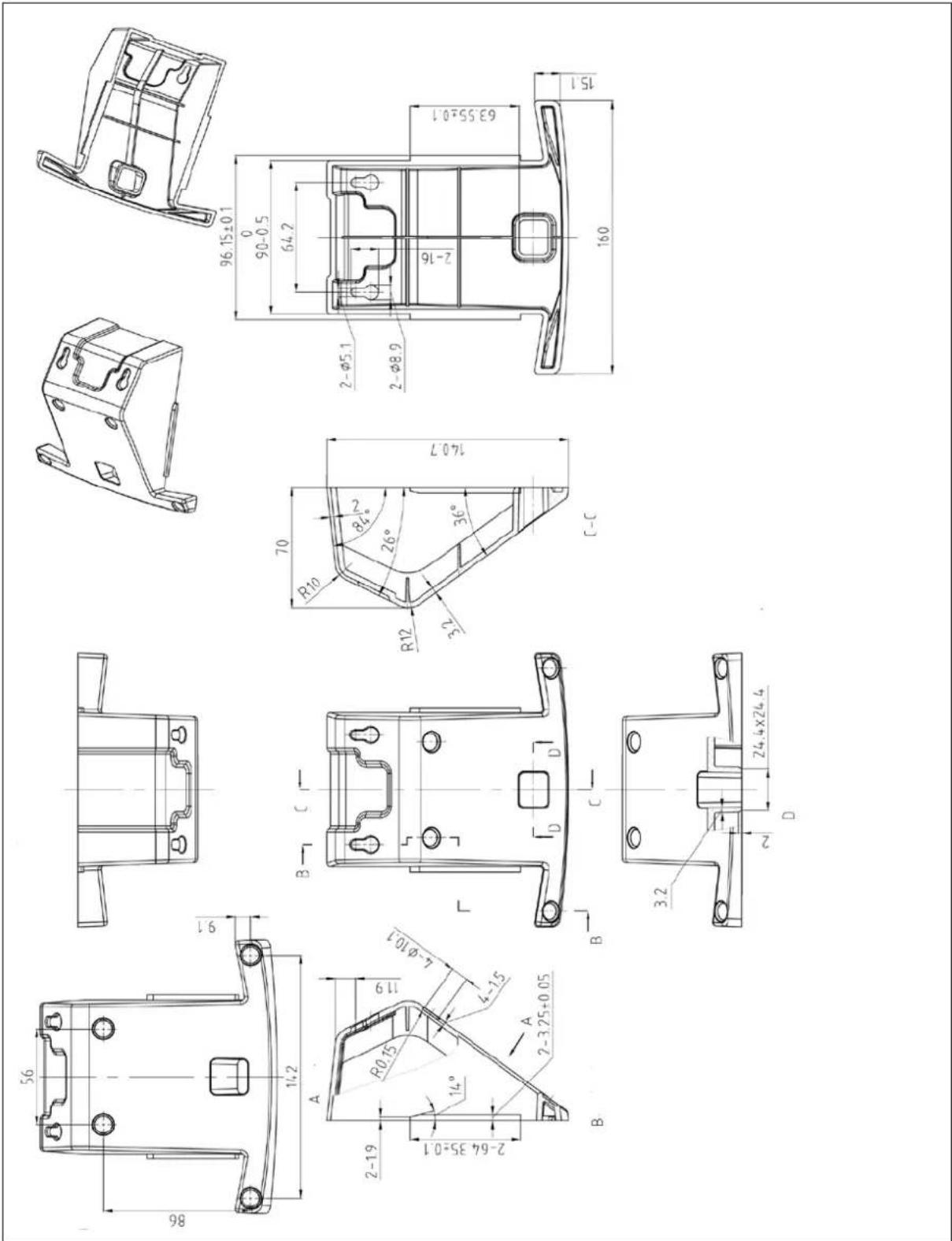
13 Annex
13.1 Dimensions Support base / wall bracket
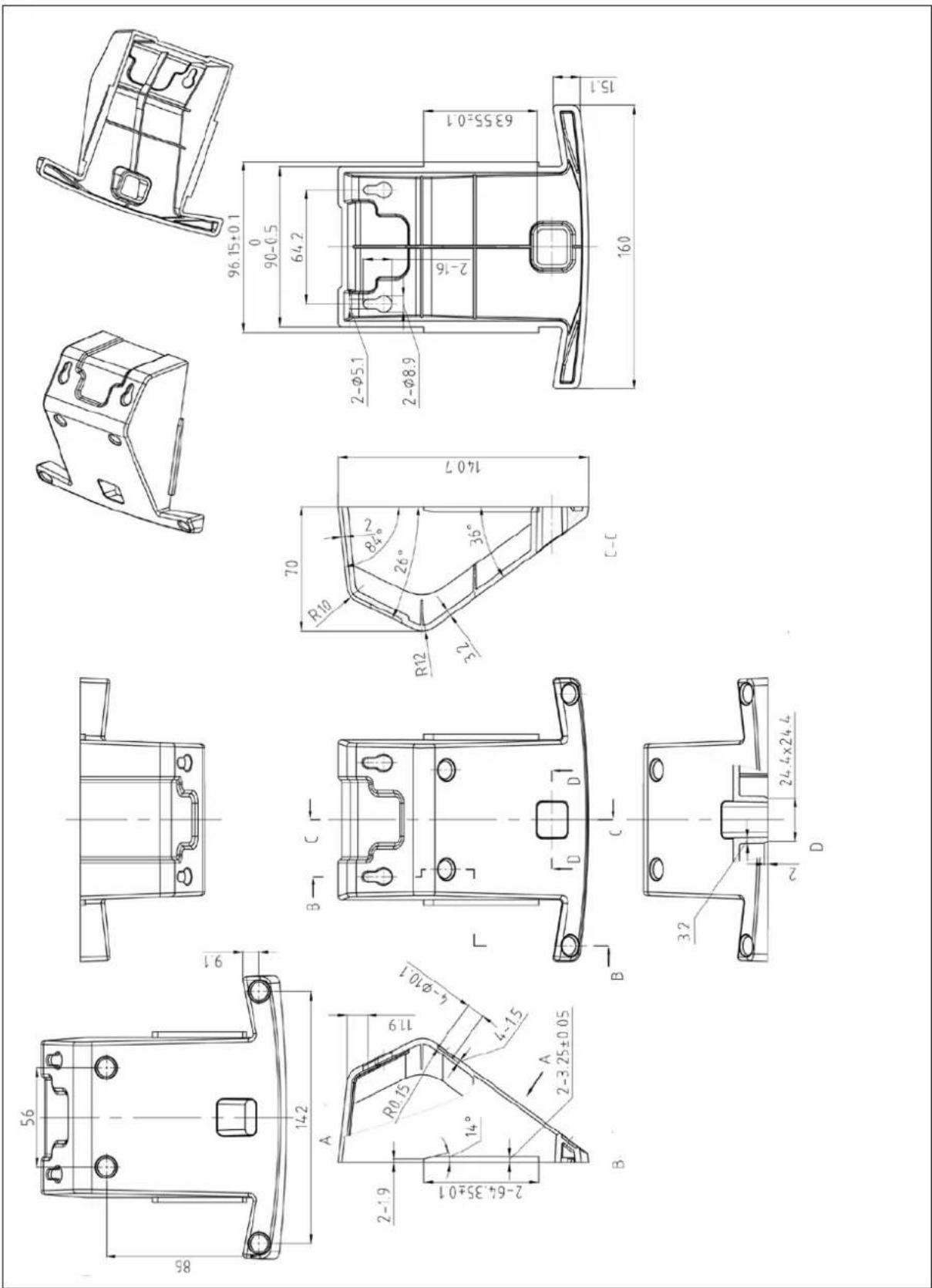
text_image
Technical engineering drawing with multiple orthographic views and dimension annotations for a mechanical part14 Declaration of Conformity / Examination Certificate
To view the current EC/EU Declaration of Conformity go to:
www.kern-sohn.com/ce
i The scope of delivery for verified weighing balances (= conformity-rated weighing balances) includes a Declaration of Conformity.

KERN KFB/KFN-TAM
Version 3.2 02/2018
text_image
[K1] 81.50-05 107-62 D#27043-MG. 07:10:24text_image
Technical diagram of a device with labeled components, showing internal and external viewstext_image
[K1] [K2]7 Fonctionnement
7.1 Mise en route
Avertissement surcharge
HEADER2: NT=NET, GS=GROSS
natural_image
Close-up of a green circuit board with multicolored wires and connectors (no readable text or symbols)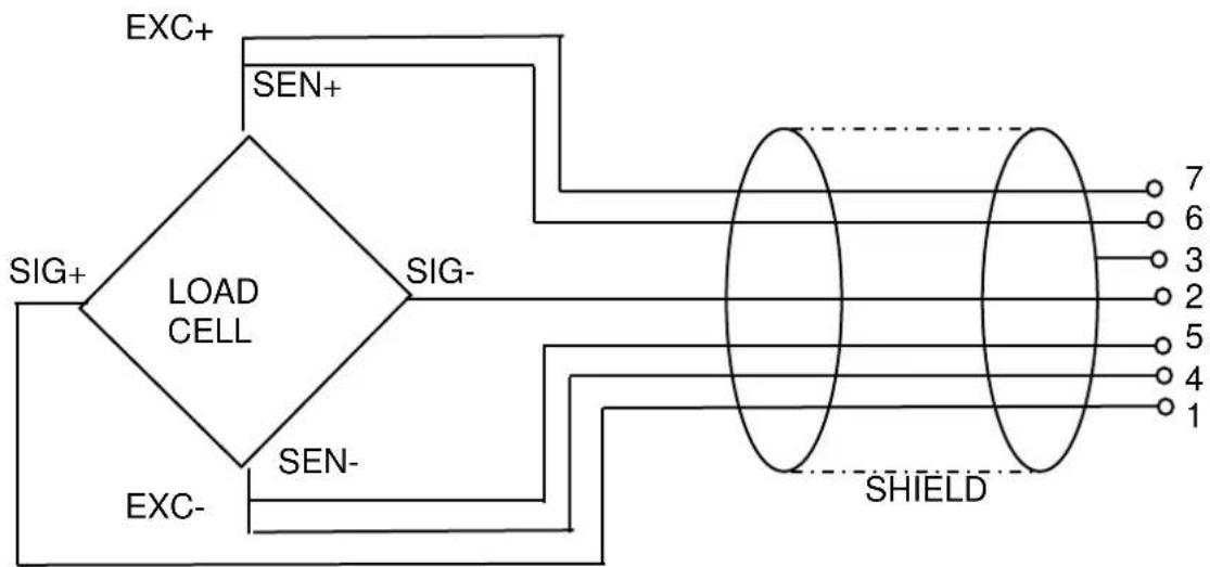
flowchart
graph TD
    A["LOAD CELL"] --> B["EXC+"]
    A --> C["SEN+"]
    A --> D["EXC-"]
    A --> E["SIG+"]
    A --> F["SIG-"]
    A --> G["SEN-"]
    H["SHIELD"] --> I["7"]
    H --> J["6"]
    H --> K["3"]
    H --> L["2"]
    H --> M["5"]
    H --> N["4"]
    H --> O["1"]
13.1 Dimensions Pied de table / support mural