
PS200 - Audiovisual wall mount Peerless-AV - Free user manual and instructions
Find the device manual for free PS200 Peerless-AV in PDF.
| Product Type | Wall mount for audiovisual equipment (shelf) |
| Brand | Peerless-AV |
| Model | PS200 |
| Maximum load capacity | 100 lb (45.4 kg) |
| Material | Steel |
| Included components | Support arms (2), wall plate, plate cover, concrete anchor plugs, wood screws, safety strap |
| Compatible wall types | Wood studs, wood beams, solid concrete, concrete block (other types require accessories or professional) |
| Required tools | Stud finder, Phillips screwdriver, drill, drill bits (5/32, 5/16, 1/2 in), level |
| Main functions | Height and depth adjustable shelf support with safety strap for devices |
| Installation | Wall mounting on wood studs or concrete, professional installation recommended |
| Maintenance and cleaning | Clean with a dry, soft cloth. Do not use abrasive products. |
| Safety | Do not exceed maximum load. Check wall solidity. Use a safety strap. |
| Warranty | Limited manufacturer's warranty (see manual) |
| Repairability | Spare parts available from the manufacturer (safety strap, screws) |
Frequently Asked Questions - PS200 Peerless-AV
User questions about PS200 Peerless-AV
0 question about this device. Answer the ones you know or ask your own.
Ask a new question about this device
Download the instructions for your Audiovisual wall mount in PDF format for free! Find your manual PS200 - Peerless-AV and take your electronic device back in hand. On this page are published all the documents necessary for the use of your device. PS200 by Peerless-AV.
USER MANUAL PS200 Peerless-AV
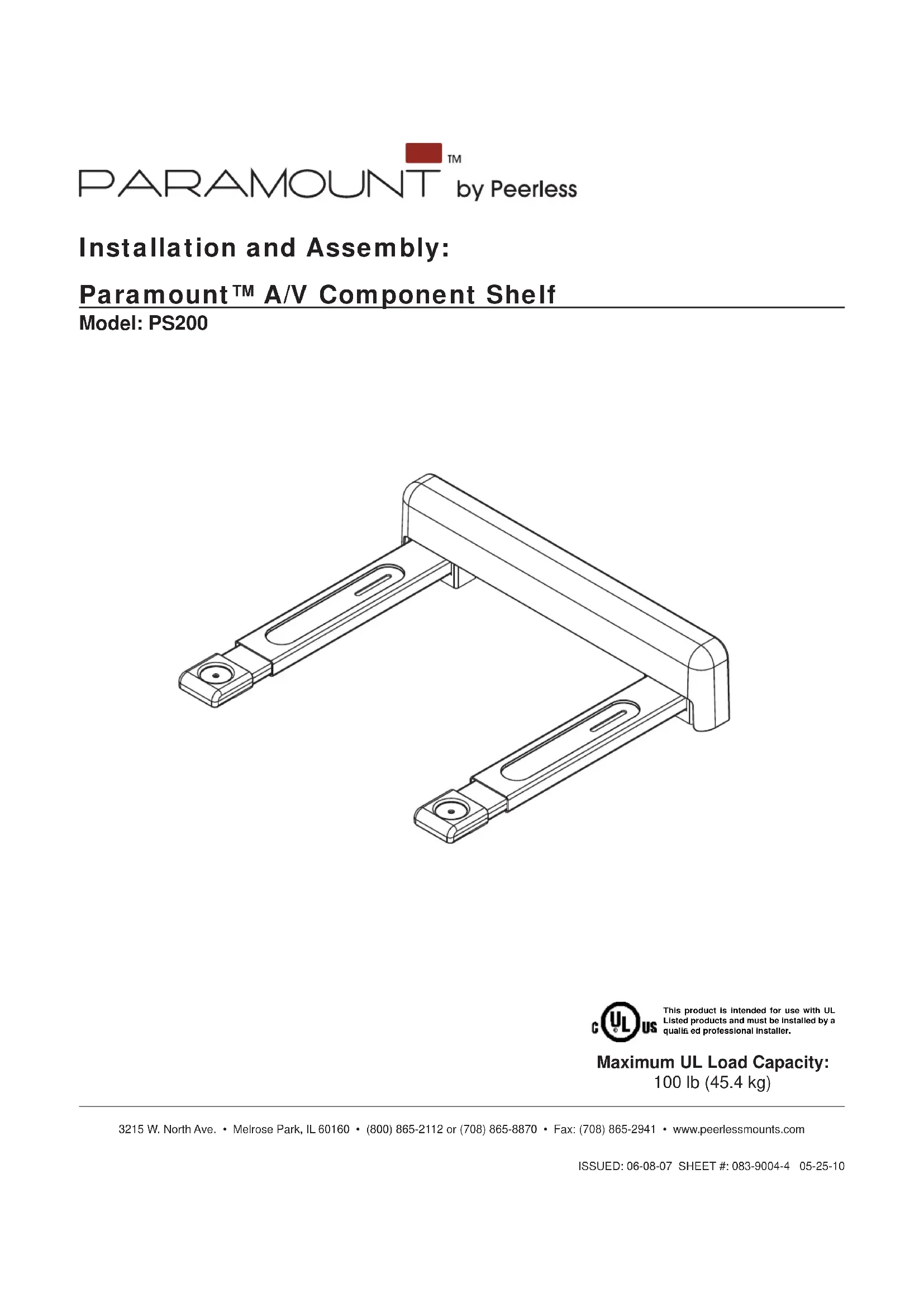
Installation and Assembly:
Paramount™ A/V Component Shelf
Model: PS200
CULUS This product is intended for use with UL Listed products and must be installed by a qualia ed professional installer. Maximum UL Load Capacity: 100 lb (45.4 kg)
WARNING
- Do not begin to install your Peerless product until you have read and understood the instructions and warnings contained in this Installation Sheet. If you have any questions regarding any of the instructions or warnings, for US customers please call Peerless customer care at 1-800-865-2112, for all international customers, please contact your local distributor.
- This product should only be installed by someone of good mechanical aptitude, has experience with basic building construction, and fully understands these instructions.
- Make sure that the supporting surface will safely support the combined load of the equipment and all attached hardware and components.
- Never exceed the Maximum Load Capacity. See page one.
- If mounting to wood wall studs, make sure that mounting screws are anchored into the center of the studs. Use of an "edge to edge" stud fi nder is highly recommended.
- Always use an assistant or mechanical lifting equipment to safely lift and position equipment.
- Tighten screws firmly, but do not overtighten. Overtightening can damage the items, greatly reducing their holding power.
This product is intended for indoor use only. Use of this product outdoors could lead to product failure and personal injury. - This product was designed to be installed on the following wall construction only;
WALL CONSTRUCTION HARDWARE REQUIRED
Wood
Stud
Included
Wood Beam
Included
Solid Concrete Incl
Included
Cinder Block
Included
Metal Stud
Do not attach except with Peerless Metal Stud Accessory Kit;
not
evaluated by
UL)
Contact Qualified Professional (not evaluated by UL)
Brick
Contact Qualified Professional
- Other or unsure?
Tools Needed for Assembly
- stud finder ("edge to edge" stud finder is recommended)
- phillips screwdriver
- drill
-
5/16" bit for concrete and cinder block wall
-
1 / 2 bit for metal stud wall
5/32" bit for wood stud wall
level
Table of Contents
Parts List. 3
Installation to Wood Stud Wall. 4
Installation to Solid Concrete or Cinder Block 5
Installing Support Arms and Wall Plate Cover 6
7
For customer care call (800) 865-2112 or (708) 865-8870.
Accessories (sold separately)
- 2 piece Metal Stud Fastener Kit (ACC 215) (Metal Stud not evaluated by UL)
- Safety Belt (ACC 322)
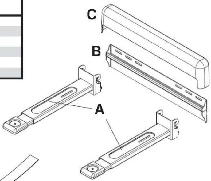
| Parts List Description Qty. Part # PS200 | |
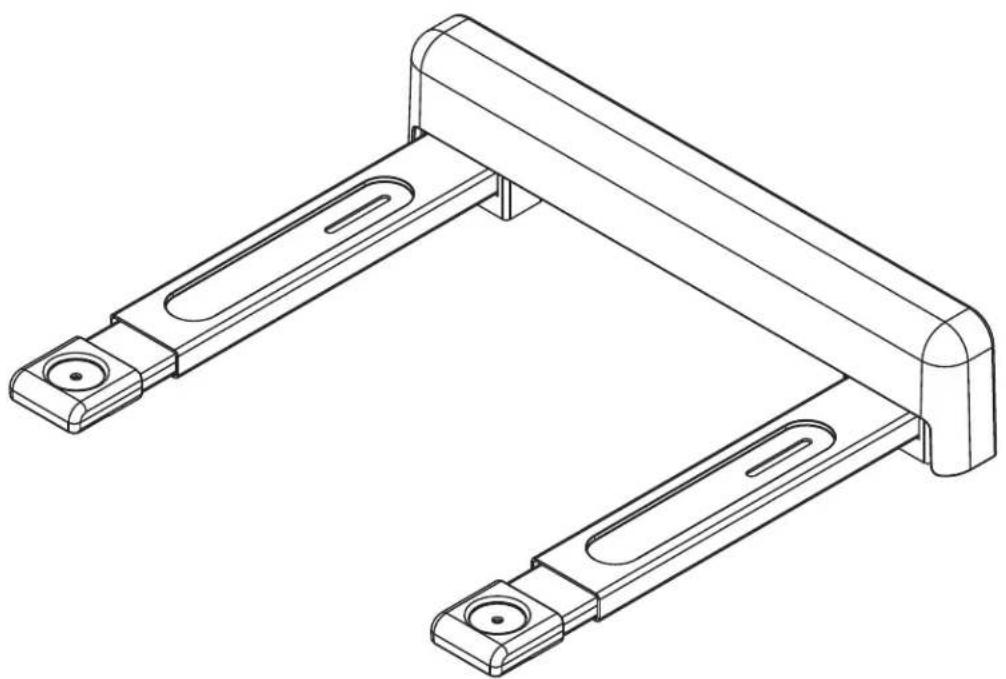
| A | support arm 2 083-0016 |
| B | wall plate 1 083-P1019 |
| C | wall plate cover 1 590-1281 |
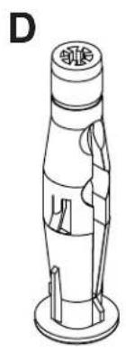
| D | concrete anchor 2 590-0320 |
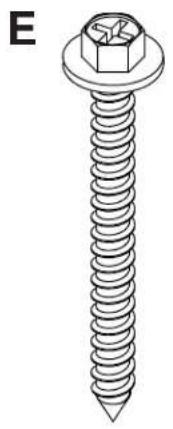
| E | #14 x 2.5" wood screw 2 5S1-015-C03 |
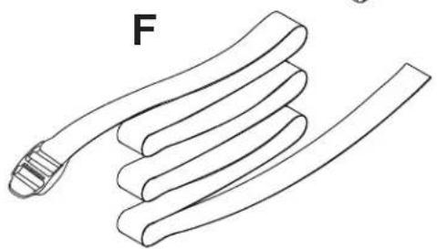
| F | safety belt 1 083-8015 |
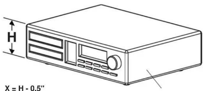
For mounting under a surface
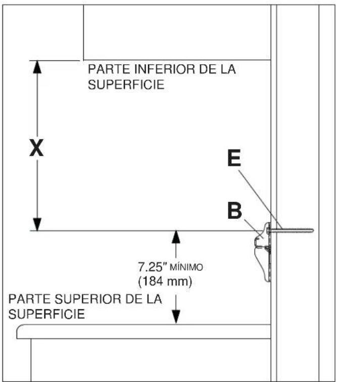
Measure the height of the component to be placed onto the mount, this measurement will be referred to as H.
Determine minimum distance X from surface bottom to mounting hole centers using the formula X = H - 0.5^ or X = H - 13mm
Note: If height of component is less than 4.5" (114 mm), a minimum distance of 4" (102 mm) is required for X.
For mounting above a surface locate mounting hole centers no less than 7.25" from surface top.
$$ X = H - 1 3 m m $$
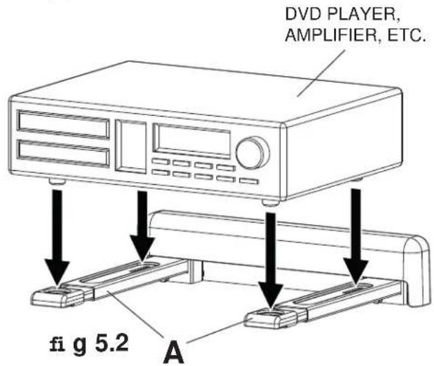
DVD PLAYER, AMPLIFIER, ETC.
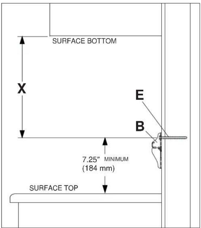
SIDE VIEW
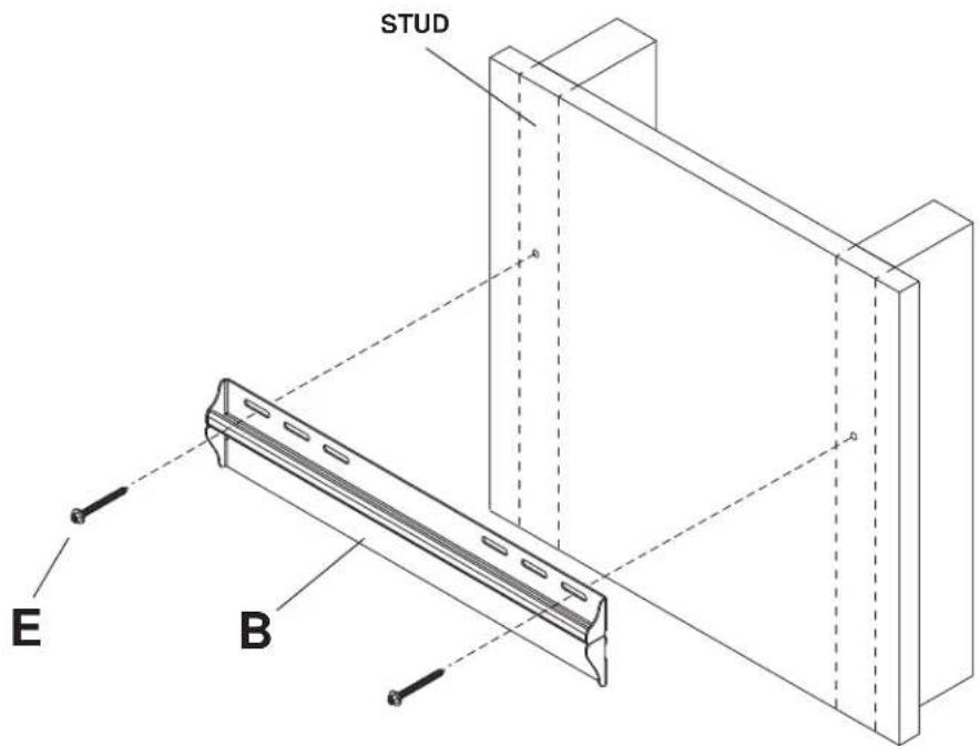
Installation to Wood Stud Wall
WARNING
- Installer must verify that the supporting surface will safely support the combined load of the equipment and all attached hardware and components.
- Tighten wood screws so that wall plate is firmly attached, but do not overtighten. Overtightening can damage the screws, greatly reducing their holding power.
- Never tighten in excess of 80 in. - lb (9 N.M.).
- Make sure that mounting screws are anchored into the center of the stud. The use of an "edge to edge" stud finder is highly recommended.
- Hardware provided is for attachment of mount through standard thickness drywall or plaster into wood studs. Installers are responsible to provide hardware for other types of mounting situations.

Wall plate (B) can be mounted to two studs that are 16^ apart. Use a stud finder to locate the edges of the studs. Use of an edge-to-edge stud finder is highly recommended. Based on their edges, draw a vertical line down each stud's center. Determine the mounting location of wall plate using the formula in step one. Place wall plate on wall as a template. Level plate, and mark the center of the two mounting holes. Make sure that the mounting holes are on the stud centerlines. Drill two 5 / 32'' (4 mm) dia. holes 2 - 1 / 2'' (64 mm) deep. Make sure that the wall plate is level, secure it using two #14 x 2.5" wood screws (E) as shown below.
Skip to step 3.
Installation to Solid Concrete or Cinder Block
WARNING
- When installing Peerless wall mounts on cinder block, verify that you have a minimum of 1-3/8" of actual concrete thickness in the hole to be used for the concrete anchors. Do not drill into mortar joints! Be sure to mount in a solid part of the block, generally 1" minimum from the side of the block. Cinder block must meet ASTM C-90 specifications. It is suggested that a standard electric drill on slow setting is used to drill the hole instead of a hammer drill to avoid breaking out the back of the hole when entering a void or cavity.
Concrete must be 2000 psi density minimum. Lighter density concrete may not hold concrete anchor. - Make sure that the supporting surface will safely support the combined load of the equipment and all attached hardware and components.

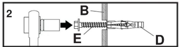
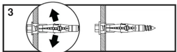
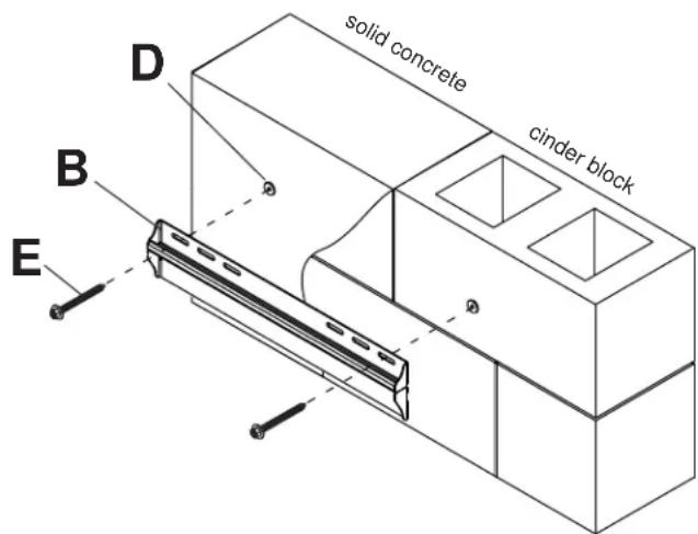
Determine the mounting location of wall plate (B) using the formula in step one. Make sure that wall plate is level, use it as a template to mark two mounting holes. Drill two 5/16'' (8 mm) dia. holes to a minimum depth of 2.5'' (64 mm). Insert anchors (D) in holes fl ush with wall as shown (right). Place wall plate over anchors and secure with # 14 × 2.5'' screws (E). Level, then tighten all fasteners.
WARNING
- Tighten screws so that wall plate is firmly attached, but do not overtighten. Overtightening can damage screws, greatly reducing their holding power.
- Never tighten in excess of 80 in. - Ib (9 N.M.).
- Always attach concrete anchors directly to load-bearing concrete.
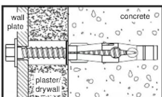
- Never attach concrete anchors to concrete covered with plaster, drywall, or other fi nishing material. If mounting to concrete surfaces covered with a fi nishing surface is unavoidable (not evaluated by UL), the fi nishing surface must be counterbored as shown below. Be sure concrete anchors do not pull away from concrete when tightening screws. If plaster/drywall is thicker than 5/8" , custom fasteners must be supplied by installer (not evaluated by UL).
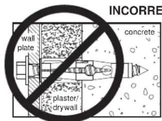
CUTAWAY VIEW
INCORRECT CORRECT
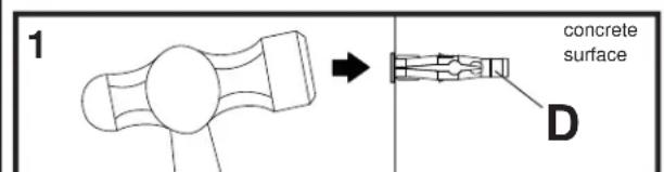
Drill holes and insert anchors (D).
Place plate (B) over anchors (D) and secure with screws (E).
Tighten all fasteners.
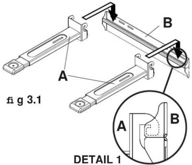
Installation of Support Arms

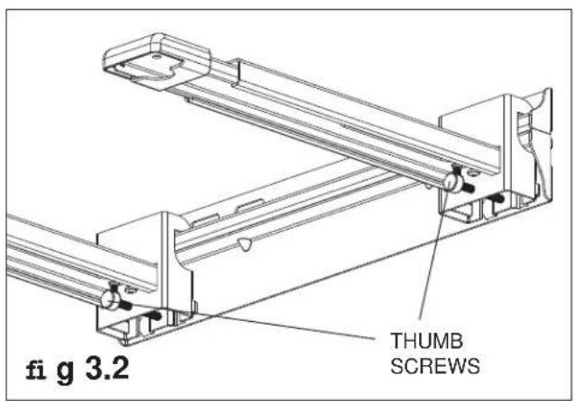
Hook support arms (A) onto wall plate (B) using hooks on support arms as shown in figure 3.1. Hooks of vertical brackets (A) must be engaged securely into wall plate as shown in detail 1.
Note: Thumb screws located underneath the support arms (A) can be turned for fine tuning level adjustment of the mount as shown in figure 3.2.

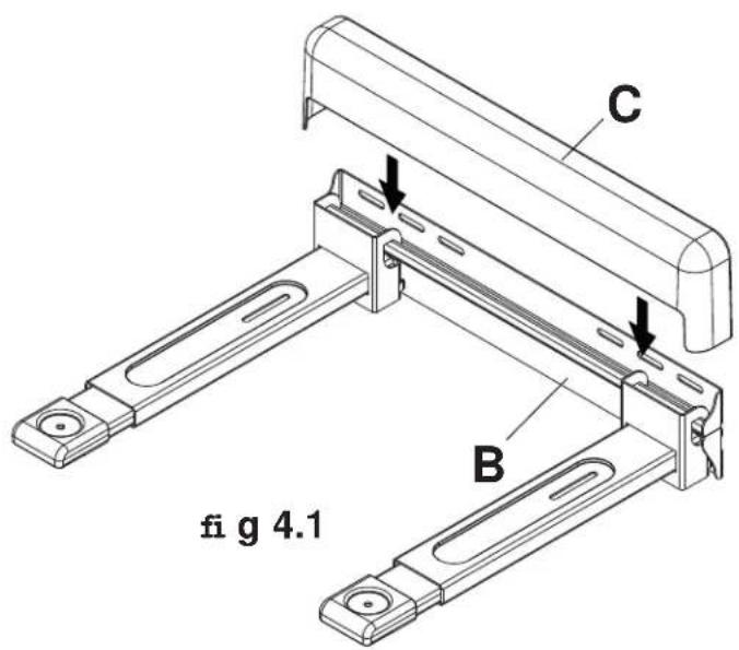
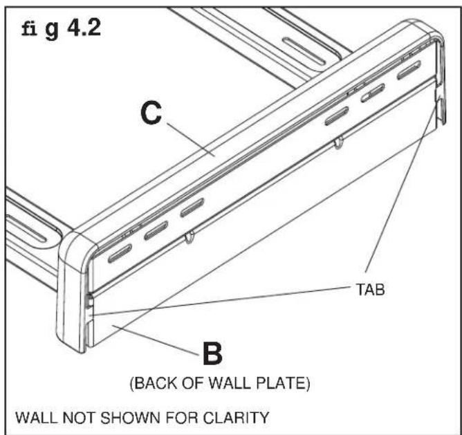
Attach wall plate cover (C) to wall plate (B) as shown in figure 4.1. Tabs on the back of cover (C) are placed into notches in the back of wall plate (B) as shown in figure 4.2.

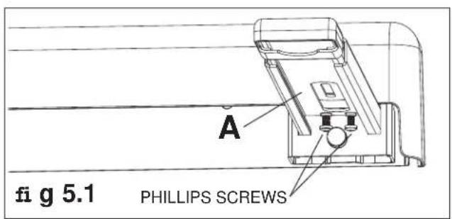
Note: Support arms (A) can be extended by loosening two phillips screws under each arm as shown in figure 5.1. Extend arm to desired position and retighten screws before placing component onto mount. Place component (DVD player, amplifier, etc.) onto support arms (A) of mount.
WARNING
- Always use an assistant or mechanical lifting equipment to safely lift and position items onto support arms.
Installation of Safety Belt

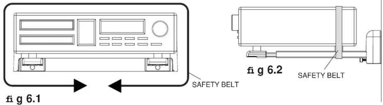
Wrap safety belt (F) around component as shown in figure 6.1. Position belt close to the back of the component being secured (in line with the back feet) as shown in fig 6.2.
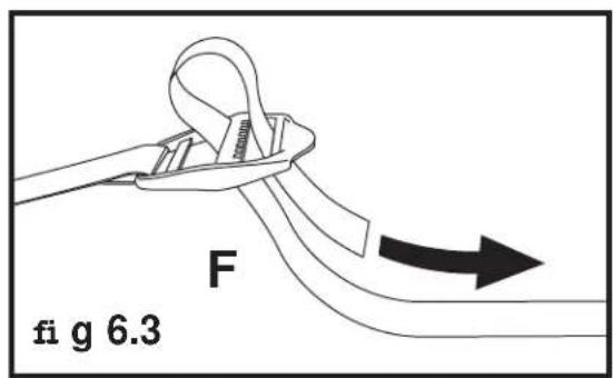
Insert loose end of safety belt into the buckle end as shown in figure 6.3. Pull to tighten securely.
PARAMOUNT TM by Peerless
$$ X = H - 0. 5 ^ {\prime \prime} $$
$$ X = H - 1 3 m m $$
TOCA DVD, AMPLIFICADOR, ETC.
VISTA LATERAL
ADVERTENCIA
PARAMOUNT TM by Peerless
- Installation and Assembly:
- Paramount™ A/V Component Shelf
- WARNING
- WALL CONSTRUCTION HARDWARE REQUIRED
- Tools Needed for Assembly
- Table of Contents
- Accessories (sold separately)
- For mounting under a surface
- Installation to Wood Stud Wall
- Installation to Solid Concrete or Cinder Block
- Installation of Support Arms
- Installation of Safety Belt
- PARAMOUNT TM by Peerless
- ADVERTENCIA
Brand : Peerless-AV
Model : PS200
Category : Audiovisual wall mount