
WM525 - Ladder BLACK & DECKER - Free user manual and instructions
Find the device manual for free WM525 BLACK & DECKER in PDF.

| Product Type | Multifunction workbench (Workmate mode, hand truck, vertical clamping) |
| Brand | Black & Decker |
| Model | WM525 |
| Load capacity (Workmate mode) | 204 kg (450 lb) maximum |
| Load capacity (hand truck mode) | 91 kg (200 lb) maximum |
| Approximate weight | 22 kg |
| Dimensions (open, Workmate mode) | Approximately 80 cm (H) x 90 cm (W) x 60 cm (D) |
| Dimensions (folded, storage mode) | Approximately 80 cm (H) x 30 cm (W) x 20 cm (D) |
| Power source | Manual (no electrical source required) |
| Materials | Metal (steel frame) and plastic (cranks, buttons) |
| Main functions | Vise with front/center/rear jaws, vertical clamping, hand truck for transporting loads |
| Number of jaw positions | 2 indexed positions (locating holes) for the rear jaw |
| Included hardware | 4 articulated claw fittings for extension |
| Accessories included | Nut driver, combination wrench, spring pins, cranks, snap-in buttons, vise screw protectors |
| Safety | Do not exceed indicated loads, do not use as a stepladder, wear safety glasses when using tools |
| Care and cleaning | Clean with a damp cloth, do not store outdoors or in a damp place |
| Spare parts and repairability | Available parts: cranks, pins, wheels, nuts, bolts, jaws. Repair by Black & Decker authorized service centers |
| Warranty | 2 years for residential use (defects in material or workmanship) |
| General information | Assembly required (estimated time: 1 hour). Storage stack: Workmate mode, hand truck mode, storage mode |
Frequently Asked Questions - WM525 BLACK & DECKER
User questions about WM525 BLACK & DECKER
0 question about this device. Answer the ones you know or ask your own.
Ask a new question about this device
Download the instructions for your Ladder in PDF format for free! Find your manual WM525 - BLACK & DECKER and take your electronic device back in hand. On this page are published all the documents necessary for the use of your device. WM525 by BLACK & DECKER.
USER MANUAL WM525 BLACK & DECKER
BLACK&DECKER® Workmate® 525
natural_image
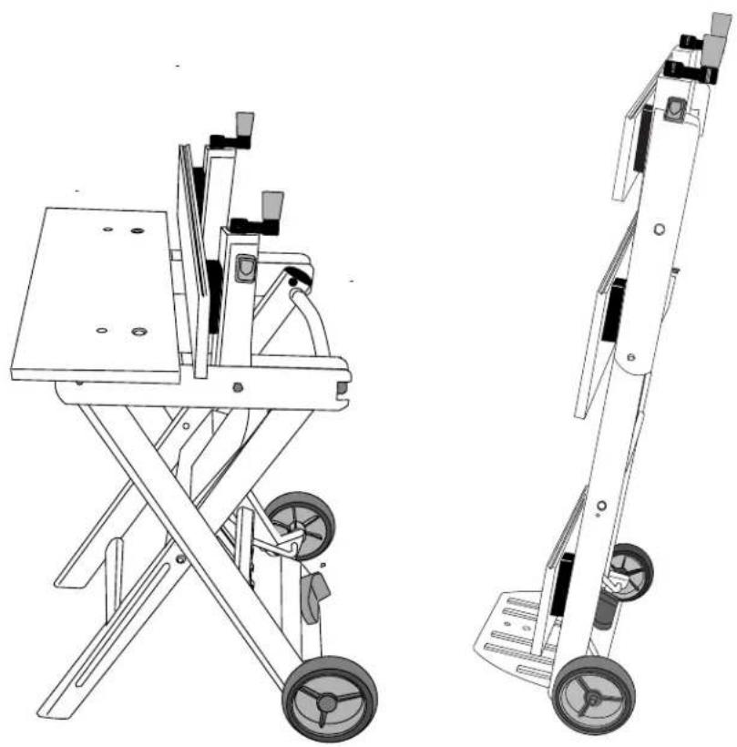
Technical line drawings of two mechanical device assemblies, one with a flat base and wheels, the other with a multi-wheel cart (no text or symbols)BEFORE RETURNING THIS PRODUCT BEFORE RET
FOR ANY REASON PLEASE CALL FOR ANY REAS
1-800-54-HOW-TO(544-6986)
IF YOU SHOULD EXPERIENCE A PROBLEM
WITH YOUR BLACK & DECKER PRODUCT,
CALL 1-800-54-HOW-TO (544-6986).
BEFORE YOU CALL, HAVE THE FOLLOWING INFORMATION
AVAILABLE, CATALOG NO., TYPE NO., AND DATE CODE.
IN MOST CASES, A BLACK & DECKER REPRESENTATIVE CAN RESOLVE
YOUR PROBLEM OVER THE PHONE. IF YOU HAVE A SUGGESTION OR
COMMENT, GIVE US A CALL. YOUR FEEDBACK IS VITAL TO BLACK & DECKER.
▲ IMPORTANT SAFETY INSTRUCTIONS
WARNING:
- Do not load with more than 450 lbs (204 kg) in Workmate Mode or 200 lbs (91 kg) in Hand Cart Mode.
- Do not apply an unbalanced load which could cause the Workmate to tip over.
- Do not step on or stand on Workmate. Do not use the Workmate as a stepladder or standing platform.
- Do not store Workmate outdoors or in a damp location.
- Avoid applying excessive force when clamping with the Swivel Grips.
- Be sure that the legs are fully open and that the Transition Lever and Toe Plate Slider locks in position. Secure Hand Cart loads to steel frame members as necessary
- When using a power tool with the Workmate, follow the safety instructions in the tool's instruction manual.
- Always wear safety glasses when operating power or hand tools.
- An even pressure of the Vise Jaws on the workpiece is essential. Tighten both Vise Hand Cranks uniformly.
- Cutting or drilling into work surface may result in striking metal jaw support below, damaging tool or work centre.
- Caution required when using high temperature tools (heat guns, torch, solder iron, etc.). May damage work surface and reduce clamping capability.
⚠ WARNING: This product contains chemicals, including lead, known to the
State of California to cause cancer, and birth defects or other reproductive harm.
Wash hands after handling.
SAVE THESE INSTRUCTIONS FOR FUTURE USE.
NOTE! The assembly of the Workmate should take approximately 1 hour.
Before you proceed to assemble you will need the following tools.
1 - Hammer
1 - Phillips Screwdriver
1 - Nut Driver (supplied - item R of Fig.1))
1 - Combination Wrench (supplied) (not shown)
Fig. 1 : Unpack
Important: Check that you have received all the parts.
Remove the contents of the carton. The following components are in the carton.
(A) 1 - Frame Assembly
(B) 2 - Vise Screw Packing Pieces (H) 4- Top Blocks
(installed to (C))
(C) 2 - Vise Brackets (J) 2- M
(I) 2- Top Blocks (one side flat)
6 x 36.5mm Bolts
(D) 1 - Front Vise Jaw (K) 2 - M6 x 30mm Bolts
(E) 1 - Middle Vise Jaw (narrow)
(F) 1 - Rear Vise Jaw (wide)
(G) 2 - Wheels (N) 4 - Swivel Grips
(L) 4 - M6 Locking Nuts
(M) 6 - M8 Bolts
(O) 2 - Spring Pins
(P) 2 - Vise Hand Cranks
(Q) 2 - Snap-in Knobs
(R) 1 - Nut Driver
(S) 2 - M8 Wheel Nuts
(T) 2 - Flat Washer
(U) 2 - Vise Screw Protectors
(not shown) 1 - Combination Wrench
Assembly:
⚠ WARNING: Wear eye protection when assembling Workmate.
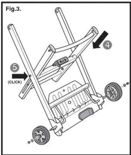
Fig. 2 & 3: Frame Assembly
- Fig. 2: Pick up the Frame Assembly (A) as shown. Place foot on the lower portion of the assembly and push the Transition Lever to the right to unlock the unit.
- While holding the Transition Lever in the unlocked position, lift up on the upper cross member until it is fully extended.
- Rotate the upper cross member toward you and push back on the lower leg assembly shown.
- Fig. 3: Continue to push down on the upper cross member until the unit locks in the fully open position.
- Note! Make sure that the locking pin, is engaged and locked into the opposite frame hole – a click sound will be heard when locked in place.
Fig. 3: Wheel Assembly
- Using Wheels (G), M8 Wheel Nuts (S) and Flat Washers (T), assemble to the axles as shown.
Tighten the M8 Wheel Nuts using the Nut Driver (R).
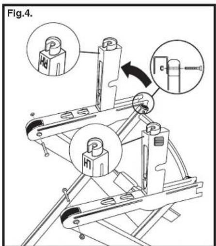
Fig. 4: Assembly of the Vise Brackets
- Assemble the left hand Vise Bracket (C) as shown (Each bracket is stamped either LH or RH).
- NOTE! The Vise Brackets must be in the "Tilt" position as shown to assemble to the legs.
- Fig. 15: Pull vertical the locking button located on the side of the Vise Bracket back toward the handle end of the unit as shown in the inset, and lift up on the tilting bracket, until the assembly locks into a vertical position.
- Fig. 4: Insert one M6 x 36.5mm Bolt (J) through the rear leg of Frame Assembly, then through the rear of the Vise Bracket as shown. Using a Phillips screwdriver and a Combination Wrench, tighten the M6 Lock Nut (L) onto the bolt.
- Assemble the front leg of the Frame Assembly to the front of the Vise Bracket (C) as shown.
- Insert one M6 x 30 mm Bolt (K) completely through the front leg assembly and then through the hole in the side of the Vise Bracket as shown. Thread an M6 Lock Nut (L) onto the end of the bolt and tighten with a Combination Wrench and Phillips screw driver.
- Repeat for the right side (RH) Vise Bracket
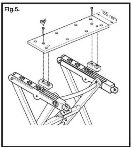
Fig. 5: Assembling the Front Vise Jaw
- Return the Tilt Bracket to the horizontal position by pulling the tilt lock button back to disengage the lock and rotate the brackets back to the horizontal position as shown.
- Assemble the front Top Blocks ((I) - one side flat) to the Front Vise Jaw (D) as shown.
- Thread an M8 Bolt (M) through the jaw, then through the mounting block.
- While holding the Vise Screw and Pivot Nut up from the underside of the Tilt Bracket, thread the M8 Bolt into the mounting hole in the pivot nut.
- Tighten the M8 Bolts using the Nut Driver (R) (or Combination Wrench provided)
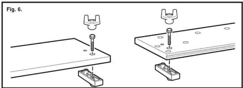
Fig. 6: Assembling the Top Blocks to the Middle and Rear Vise Jaws
- Assemble two Top Blocks (H) to the underside of the Rear Vise Jaw (F) by fitting the raised posts on the Top Blocks into the smaller holes of the Rear Vise Jaw.
- Insert the M8 Bolts (M) through top of the Rear Vise Jaw and into the Top Blocks
- Tighten the M8 Bolts using the Nut Driver (R) (or Combination Wrench provided)
- Assemble the Top Blocks (H) to the Middle Vise Jaw (E) using the same procedure as the Rear Vise Jaw.
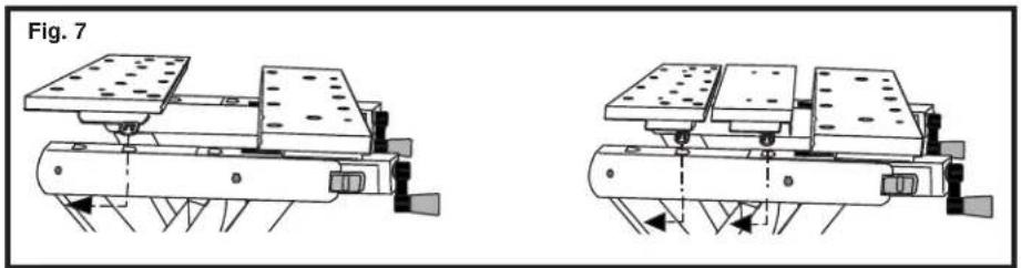
Fig. 7: Installing the Rear Vise Jaw
- Install Rear Vise Jaw (F) in one of 2 possible indexed "keyhole" positions by inserting the indexing lug into a keyhole in the Vise Bracket.
- Secure the Rear Vise Jaw by moving the Rear Vise Jaw to the back of the key hole.
Fig. 8, 9 & 10: Installing the Vise Hand Cranks and Snap-in Knobs
- Fig. 8: Remove and discard the plastic Vise Screw Packing Pieces (B).
- Align the hole in the Vise Hand Crank (P) with the hole in the Vise Screw (area you removed the vise screw packing pieces from), push the Vise Hand Crank onto the end of the Vise Screw and realign the holes.
- Using a hammer, drive the supplied Spring Pin (O) into the aligned holes.
- Repeat this procedure for the installation of the other Vise Hand Crank.
- Fig. 9: Complete the assembly by pushing the Snap-in Knobs (Q) into the holes in the Vise Hand Cranks.
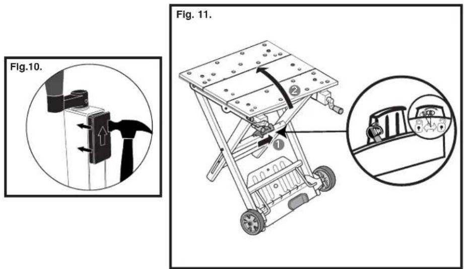
- Fig. 10: Tap the Vise Screw Protectors (U) into position as shown.
Reference Fig. 7: Installing the Middle Vise Jaw:
- Install the Rear Vise Jaw into the back keyholes.
- With Front Vise Jaw cranked to the front of the work center, insert the indexing lugs of the Middle Vise Jaw into the front keyholes.
- Turn Hand Cranks clockwise to tighten.
Fig. 11: Workmate Mode
After assembly the unit is in the Workmate mode.
Operation:
Fig.11 & 12: Storage Mode
- Fig. 11: To close the unit from the workmate mode, push and hold the Transition Lever (shown in the inset) to the right to unlock the unit.
- Pull up on the upper cross member as shown.
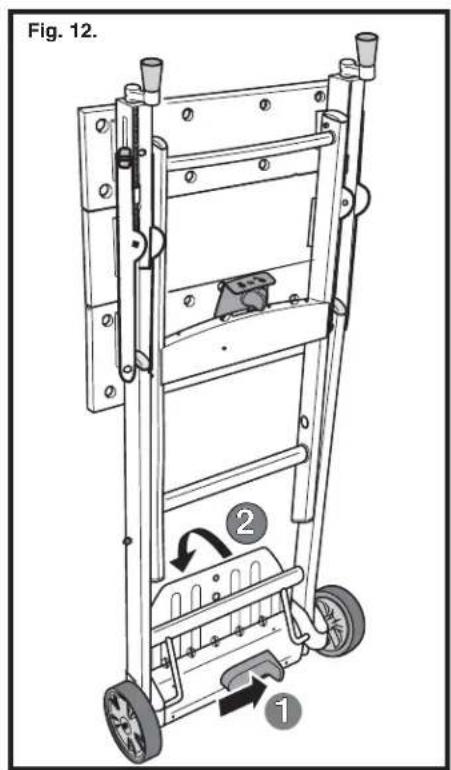
- Fig. 12: Release the Transition Lever and check that the unit is locked in the storage position as shown.
Fig.12 & 13: Hand Cart Mode
- Fig. 12: With the unit in storage mode, use your foot to slide the Toe Plate Slider fully to the right as shown in the inset.
- Maintain Toe Plate Slider in this position while pushing forward and down on the Toe Plate. This will release the locking mechanism and allow the Toe Plate to rotate forward.
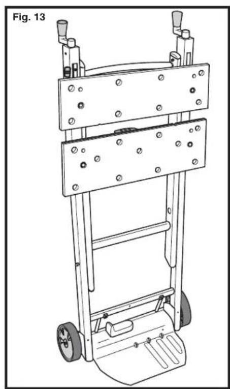
- Fig. 13: The Toe Plate will lock in place when in the working position.
- To stow the Toe Plate feature, reverse the operation.
- With your foot slide the Toe Plate Slider to the right.
- Continue the pressure on the slider and press down on the back of the Toe Plate with your foot.
- The Toe Plate should rotate up and back to the upright position.
- When the Toe Plate can go no further, simply release the slider and the Toe Plate will lock into place.
- Check the Toe Plate is locked by tilting back and then forward on the top of the unit.
Fig. 14 & 11: To Convert Back Into Workmate Mode Note: Ensure Toe Plate is in the upright (storage) position.
- Push the Transition Lever (shown in the inset of Fig. 11) to the right to unlock the unit.
- Fig. 14: Push down on the upper cross member as shown.
- Fig. 11: Continue to push down until the unit locks (pins lock into outside frame) in the Workmate position.
Features & Applications:
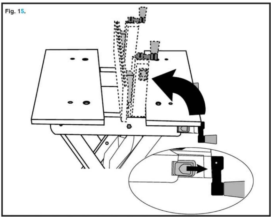
Fig. 15: Vertical Clamping
Note: Rear Vise Jaw must be in the rear keyhole position.
Rotate the Vise Hand Cranks counter clockwise to open the workmate jaws to the extreme front position. Pull the vertical locking buttons located on each side of the Vise Brackets back toward the handle end of the unit as shown in the inset, and lift up on the Front Vise Jaw, rotating until the jaw locks in the vertical position.
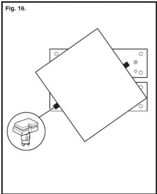
Fig. 16: Swivel Grips
The four supplied Swivel Grips (N) can be used in any of the holes in the Front and Rear Vise Jaws. The Swivel Grips are used to extend the size of your Workmate's holding capacity.
Service Information
Black & Decker offers a full network of company-owned and Authorized Service locations throughout North America. All Black & Decker Service Centers are staffed with trained personnel to provide customers with efficient and reliable power tool service. Whether you need technical advice, repair, or genuine factory replacement parts, contact the Black & Decker service location nearest you. To find your local service location, refer to the yellow page directory under "Tools—Electric" or call: 1-800-54-HOW-TO.
Full Two-Year Home Use Warranty
Black & Decker (U.S.) Inc. warrants this product for two years against any defects in material or workmanship. The defective product will be replaced or repaired at no charge in either of two ways:
The first, which will result in exchanges only, is to return the product to the retailer from whom it was purchased (provided that the store is a participating retailer). Returns should be made within the time period of the retailer's policy for exchanges (usually 30 to 90 days after the sale). Proof of purchase may be required. Please check with the retailer for their specific return policy regarding returns that are beyond the time set for exchanges.
The second option is to take or send the product (prepaid) to a Black & Decker owned or authorized Service Center for repair or replacement at our option.
Proof of purchase may be required. Black & Decker owned and authorized service centers are listed under "Tools-Electric" in the yellow pages of the phone directory. This warranty does not apply to accessories. This warranty gives you specific legal rights and you may have other rights which vary from state to state. Should you have any questions, contact the manager of your nearest Black & Decker Service Center. This product is not intended for commercial use.
See 'Tools-Electric' – Yellow Pages – for Service & Sales


Black & Decker (U.S.) Inc., 701 E. Joppa Rd. Towson, MD 21286 U.S.A.
GUIDE D'UTILISATION
Black & Decker Canada Inc.
100 Central Ave.
Col. Industrial Bravo
GUADALAJARA, JAL
Av. La Paz #1779
(33) 3825 6978
Col. Americana Sector Juarez
MEXICO, D.F.
Local D, Col. Obrera
MERIDA, YUC
Calle 63 #459-A
(999) 928 5038
Col. Centro
MONTERREY, N.L.

natural_image
Technical line drawings of mechanical components with no visible text or symbols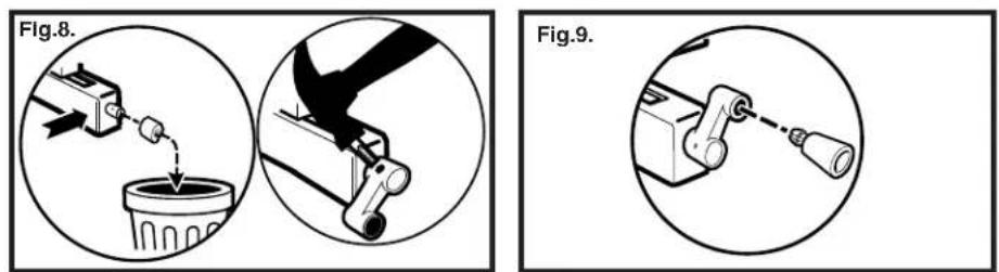
natural_image
Technical line drawing of a mechanical lift or cart with wheels and mounting holes (no text or symbols)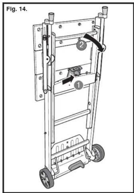
natural_image
Diagram showing a tilted square plate mounted on two plates, with an inset image of a mechanical component (no text or symbols)588974-03,01,WM525* 9/24/04 2:07 PM Page 20