DCN45 - Stapler DEWALT - Free user manual and instructions
Find the device manual for free DCN45 DEWALT in PDF.
Download the instructions for your Stapler in PDF format for free! Find your manual DCN45 - DEWALT and take your electronic device back in hand. On this page are published all the documents necessary for the use of your device. DCN45 by DEWALT.
USER MANUAL DCN45 DEWALT
English (original instructions) Definitions: Safety Alert Symbols and Words This instruction manual uses the following safety alert symbols and words to alert you to hazardous situations and your risk of personal injury or property damage.
DANGER: Indicates an imminently hazardous situation which, if not avoided, will result in death or seriousinjury.
WARNING: Indicates a potentially hazardous situation which, if not avoided, could result in death or seriousinjury.
CAUTION: Indicates a potentially hazardous situation which, if not avoided, may result in minor or moderateinjury.
(Used without word) Indicates a safety related message. NOTICE: Indicates a practice not related to personal injury which, if not avoided, may result in propertydamage.
WARNING! Read all safety warnings and all instructions. Failure to follow the warnings and instructions may result in electric shock, fire and/or seriousinjury.
WARNING: To reduce the risk of injury, read the
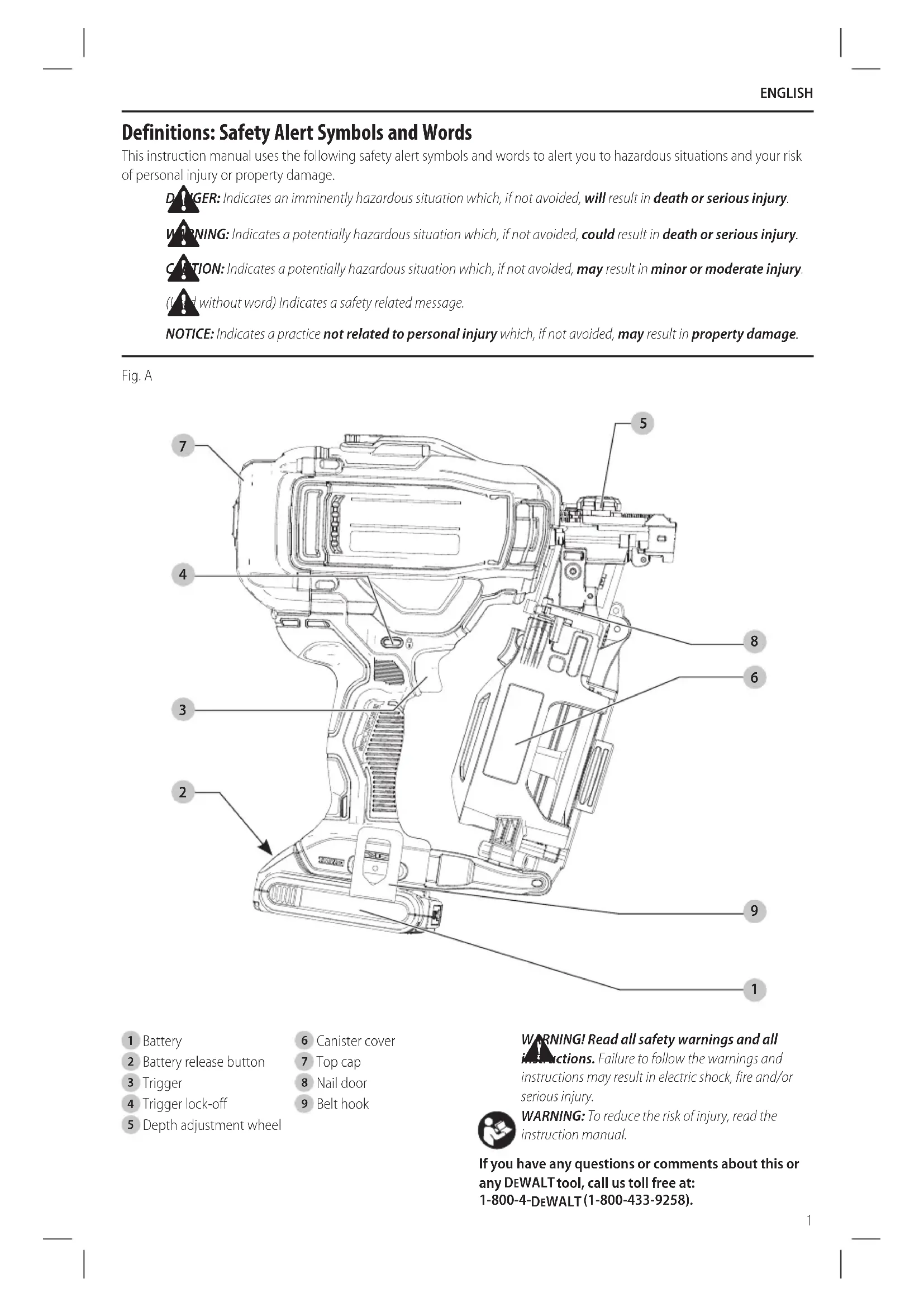
Battery release button
Depth adjustment wheel
WARNING: Read all safety warnings,
instructions, illustrations and specifications provided with this power tool. Failure to follow all instructions listed below may result in electric shock, fire and/or seriousinjury.
AND INSTRUCTIONS FOR
FUTURE REFERENCE. The term “power tool” in the warnings refers to your mains- operated (corded) power tool or battery-operated (cordless) powertool.
a ) Keep work area clean and well lit. Cluttered or dark areas inviteaccidents. b ) Do not operate power tools in explosive atmospheres, such as in the presence of flammable liquids, gases or dust. Power tools create sparks which may ignite the dust orfumes. c ) Keep children and bystanders away while operating a power tool. Distractions can cause you to losecontrol.
2) Electrical Safety
a ) Power tool plugs must match the outlet. Never modify the plug in any way. Do not use any adapter plugs with earthed (grounded) power tools. Unmodified plugs and matching outlets will reduce risk of electricshock. b ) Avoid body contact with earthed or grounded surfaces, such as pipes, radiators, ranges and refrigerators. There is an increased risk of electric shock if your body is earthed orgrounded. c ) Do not expose power tools to rain or wet conditions. Water entering a power tool will increase the risk of electricshock. d ) Do not abuse the cord. Never use the cord for carrying, pulling or unplugging the power tool. Keep cord away from heat, oil, sharp edges or moving parts. Damaged or entangled cords increase the risk of electricshock. e ) When operating a power tool outdoors, use an extension cord suitable for outdoor use. Use of a cord suitable for outdoor use reduces the risk of electricshock. f ) If operating a power tool in a damp location is unavoidable, use a ground fault circuit interrupter (GFCI) protected supply. Use of a GFCI reduces the risk of electricshock.
a ) Stay alert, watch what you are doing and use common sense when operating a power tool. Do not use a power tool while you are tired or under the influence of drugs, alcohol or medication. A moment of inattention while operating power tools may result in serious personalinjury. b ) Use personal protective equipment. Always wear eye protection. Protective equipment such as a dust mask, non-skid safety shoes, hard hat, or hearing protection used for appropriate conditions will reduce personalinjuries. c ) Prevent unintentional starting. Ensure the switch is in the off-position before connecting to power source and/or battery pack, picking up or carrying the tool. Carrying power tools with your finger on the switch or energizing power tools that have the switch on invitesaccidents. d ) Remove any adjusting key or wrench before turning the power tool on. A wrench or a key left attached to a rotating part of the power tool may result in personalinjury. e ) Do not overreach. Keep proper footing and balance at all times. This enables better control of the power tool in unexpectedsituations. f ) Dress properly. Do not wear loose clothing or jewelry. Keep your hair, clothing and gloves away from moving parts. Loose clothes, jewelry or long hair can be caught in movingparts. g ) If devices are provided for the connection of dust extraction and collection facilities, ensure these are connected and properly used. Use of dust collection can reduce dust-relatedhazards. h ) Do not let familiarity gained from frequent use of tools allow you to become complacent and ignore tool safety principles. A careless action can cause severe injury within a fraction of asecond.
4) Power Tool Use and Care
a ) Do not force the power tool. Use the correct power tool for your application. The correct power tool will do the job better and safer at the rate for which it wasdesigned. b ) Do not use the power tool if the switch does not turn it on and off. Any power tool that cannot be controlled with the switch is dangerous and must berepaired. c ) Disconnect the plug from the power source and/ or remove the battery pack, if detachable, from the power tool before making any adjustments, changing accessories, or storing power tools. Such preventive safety measures reduce the risk of starting the power toolaccidentally. d ) Store idle power tools out of the reach of children and do not allow persons unfamiliar with the power tool or these instructions to operate the power tool. Power tools are dangerous in the hands of untrainedusers. e ) Maintain power tools and accessories. Check for misalignment or binding of moving parts, breakage of parts and any other condition that may affect the power tool’s operation. If damaged, have the power tool repaired before use. Many accidents are caused by poorly maintained powertools. f ) Keep cutting tools sharp and clean. Properly maintained cutting tools with sharp cutting edges are less likely to bind and are easier tocontrol. g ) Use the power tool, accessories and tool bits etc. in accordance with these instructions, takingEnglish
- Always assume that the tool contains fasteners. Careless handling of the nailer can result in unexpected firing of fasteners and personalinjury.
- Do not point the tool towards yourself or anyone nearby. Unexpected triggering will discharge a fastener causing aninjury.
- Do not actuate the tool unless the tool is placed firmly against the workpiece. If the tool is not in contact with the workpiece, the fastener may be deflected away from yourtarget.
- Disconnect the tool from the power source when the fastener jams in the tool. While removing a jammed fastener, the nailer may be accidentally activated if it is pluggedin.
- Do not use this nailer for fastening electrical cables. It is not designed for electric cable installation and may damage the insulation of electric cables thereby causing electric shock or firehazards. Additional Nailer Safety Warnings
WARNING: When using any nailer, all safety
precautions, as outlined below, should be followed to avoid the risk of death or serious injury. Read and understand all instructions before operating thetool.
lubricants or cleaning solvents inside the tool. This can seriously affect the life and performance of thetool.
WARNING: If the tool has been dropped or you
suspect tool damage perform tool operation check as defined in the mode selection section of the manual. If it doesn’t perform according to the manual, stop using the tool and have it serviced at an authorized DeWALT
- Keep hands and body parts away from the discharge area of the tool. While in use NEVER grasp the tool by the magazine or canister, a mis-driven nail can exit the nose causing injury.
- Hold tool by insulated gripping surfaces when performing an operation where the fastener may contact hidden wiring. Contact with a “live” wire will make exposed metal parts of the tool “live” and shock theoperator.
- Actuating tool may result in flying debris, collation material, or dust which could harm operator’s eyes. Operator and others in work area MUST wear safety glasses with side shields. These safety glasses must conform to ANSI Z87.1 requirements (approved glasses have “Z87” printed or stamped on them. It is the employer’s responsibility to enforce the use of eye protection equipment by the tool operator and other people in the workarea.
- Always wear appropriate personal hearing and other protection during use. Under some conditions and duration of use, noise from this product may contribute to hearingloss. into account the working conditions and the work to be performed. Use of the power tool for operations different from those intended could result in a hazardoussituation. h ) Keep handles and grasping surfaces dry, clean and free from oil and grease. Slippery handles and grasping surfaces do not allow for safe handling and control of the tool in unexpectedsituations.
5) Battery Tool Use and Care
a ) Recharge only with the charger specified by the manufacturer. A charger that is suitable for one type of battery pack may create a risk of fire when used with another batterypack. b ) Use power tools only with specifically designated battery packs. Use of any other battery packs may create a risk of injury andfire. c ) When battery pack is not in use, keep it away from other metal objects, like paper clips, coins, keys, nails, screws or other small metal objects, that can make a connection from one terminal to another. Shorting the battery terminals together may cause burns or afire. d ) Under abusive conditions, liquid may be ejected from the battery; avoid contact. If contact accidentally occurs, flush with water. If liquid contacts eyes, additionally seek medical help. Liquid ejected from the battery may cause irritation orburns. e ) Do not use a battery pack or tool that is damaged or modified. Damaged or modified batteries may exhibit unpredictable behavior resulting in fire, explosion or risk ofinjury. f ) Do not expose a battery pack or tool to fire or excessive temperature. Exposure to fire or temperature above 265 °F (130°C) may causeexplosion. g ) Follow all charging instructions and do not charge the battery pack or tool outside the temperature range specified in the instructions. Charging improperly or at temperatures outside the specified range may damage the battery and increase the risk of fire.
a ) Have your power tool serviced by a qualified repair person using only identical replacement parts. This will ensure that the safety of the power tool ismaintained. b ) Never service damaged battery packs. Service of battery packs should only be performed by the manufacturer or authorized serviceproviders.ENGLISH
- Disconnect battery pack from the tool when not in use. Always remove battery pack and remove fasteners from magazine before leaving the area or passing the tool to another operator. Do not carry tool to another work area in which changing location involves the use of scaffoldings, stairs, ladders, and the like, with battery pack connected. Do not make adjustments, perform maintenance or clear jammed fasteners while battery is inplace.
- Do not remove, tamper with, or otherwise cause the tool, trigger or trigger lock-off, to become inoperable. Do not tape or tie trigger in the on position. Do not remove spring from contact trip. Make daily inspections for free movement of trigger. Uncontrolled discharge couldresult.
- Inspect tool before use. Do not operate a tool if any portion of the tool, trigger, or trigger lock-off is inoperable, disconnected, altered, or not working properly. Damaged parts or missing parts should be repaired or replaced before use. Refer toRepairs.
- Do not alter or modify the tool in anyway.
- Always assume that the tool containsfasteners.
- Do not point the tool at co-workers or yourself at any time. No horseplay! Work safe! Respect the tool as a workingimplement.
- Keep bystanders, children, and visitors away while operating a power tool. Distractions can cause you to lose control. When tool is not in use, it should be locked in a safe place, out of the reach ofchildren.
- Always use trigger lock-off when tool is not in immediate use. Using the trigger lock-off will prevent accidentaldischarge.
- Do not overreach. Maintain proper footing and balance at all times. Loss of balance may cause personalinjury.
- Use the tool only for its intended use. Do not discharge fasteners into open air, concrete, stone, extremely hard woods, knots or any material too hard for the fastener to penetrate. Do not use the body of the tool or top cap as a hammer. Discharged fastener may follow unexpected path and causeinjury.
- Always keep fingers clear of contact trip to prevent injury from inadvertent release of thepusher.
- Refer to the Maintenance and Repairs sections for detailed information on the proper maintenance of thetool.
- Always operate the tool in a clean, lighted area. Be sure the work surface is clear of any debris and be careful not to lose footing when working in elevated environments such asrooftops.
- Do not drive fastener near edge of material. The workpiece may split causing the nail to ricochet, injuring you or a co-worker. Be aware that the fastener may follow the grain of the wood (shiner), causing it to protrude unexpectedly from the side of the work material. Drive the chisel point of the fastener perpendicular to the grain to reduce risk ofinjury.
- Do not drive nails onto the heads of other fasteners or with the tool at too steep an angle. Personal injury from strong recoil jammed nails, or ricocheted nails mayresult.
- Keep hands and body parts clear of immediate work area. Hold workpiece with clamps when necessary to keep hands and body out of potential harm. Be sure the workpiece is properly secured before pressing the nailer against the material. The contact trip may cause the work material to shiftunexpectedly.
- Do not use tool in the presence of flammable dust, gases or fumes. The tool may produce a spark that could ignite gases causing a fire. Driving a nail into another nail may also cause aspark.
- Keep face and body parts away from back of the tool cap when working in restricted areas. Sudden recoil can result in impact to the body, especially when nailing into hard or densematerial.
- Grip tool firmly to maintain control while allowing tool to recoil away from work surface as fastener is driven. In Bump mode if contact trip is allowed to recontact work surface before trigger is released an unwanted fastener will befired.
- Choice of triggering method is important. Check the manual for triggeringoptions.
- Always select an actuation system that is appropriate to the fastener application and the training of theoperator.
- Use caution when handling, loading or unloading fasteners. Fasteners have sharp points which could causeinjury.
- Only wear gloves that provide adequate feel and safe control of the trigger and any adjustingdevices. Bump Action
- When using the tool in bump action, be careful of unin tentional double fires resulting from tool recoil. Unwanted fasteners may be driven if the contact trip is allowed to accidentally re-contact the worksurface.
- To Avoid Double Fires: ʵ Do not engage the tool against the work surface with a strongforce. ʵ Allow the tool to recoil fully after eachactuation.
- When bump actuating the roofing nailer, always keep tool in control. Inaccurate placement of tool can result in misdirected discharge of anail.
- Be aware of material thickness when using nailer. A protruding nail may causeinjury.
- Depth adjustment: To reduce risk of serious injury from accidental actuation when attempting to adjust depth, ALWAYS; ʵ Remove batterypack. ʵ Engage trigger lock-off. ʵ Avoid contact with trigger during adjustments
- Do not drive nails blindly into walls, floors or other work areas. Fasteners driven into live electrical wires,English
Important Safety Instructions for All Battery Packs
WARNING: Read all safety warnings,
instructions, and cautionary markings for the battery pack, charger and product. Failure to follow the warnings and instructions may result in electric shock, fire and/or seriousinjury.
- Do not charge or use the battery pack in explosive atmospheres, such as in the presence of flammable liquids, gases or dust. Inserting or removing the battery pack from the charger may ignite the dust orfumes.
- When battery pack is not in use, keep it away from other metal objects, like paper clips, coins, keys, nails, screws, or other small metal objects, that can make a connection from one terminal to another. Shorting the battery terminals together may cause burns or afire.
- NEVER force the battery pack into the charger. DO NOT modify the battery pack in any way to fit into
BATTERIES AND CHARGERS
The battery pack is not fully charged out of the carton. Before using the battery pack and charger, read the safety instructions below and then follow charging proceduresoutlined. When ordering replacement battery packs, be sure to include the catalog number andvoltage. The label on your tool may include the following symbols. The symbols and their definitions are asfollows: V ......................... volts Hz .......................hertz min ..................... minutes or DC ......direct current ...................... Class I Construction (grounded) …/min ..............per minute BPM .................... beats per minute IPM ..................... impacts per minute RPM .................... revolutions per minute sfpm ................... surface feet per minute SPM .................... strokes per minute OPM .................... oscillations per minute A ......................... amperes W ........................watts or AC ...........alternating current or AC/DC .... alternating or direct current ...................... Class II Construction (double insulated)
of it. Damage or personal injury couldresult.
WARNING: ALWAYS use safety glasses. Everyday
eyeglasses are NOT safety glasses. Also use face or dust mask if operation is dusty. ALL USERS AND
WARNING: Some dust created by power sanding,
sawing, grinding, drilling, and other construction activities contains chemicals known to the State of California to cause cancer, birth defects or other reproductive harm. Some examples of these chemicalsare:
- lead from lead-based paints,
- crystalline silica from bricks and cement and other masonry products, and
- arsenic and chromium from chemically- treatedlumber. Your risk from these exposures varies, depending on how often you do this type of work. To reduce your exposure to these chemicals: work in a well ventilated area, and work with approved safety equipment, such as those dust masks that are specially designed to filter out microscopicparticles.
- Avoid prolonged contact with dust from power sanding, sawing, grinding, drilling, and other construction activities. Wear protective clothing and wash exposed areas with soap and water. Allowing dust to get into your mouth, eyes, or lay on the skin may promote absorption of harmfulchemicals.
WARNING: Use of this tool can generate and/
or disperse dust, which may cause serious and permanent respiratory or other injury. Always use NIOSH/OSHA approved respiratory protection appropriate for the dust exposure. Direct particles away from face andbody.
WARNING: Always wear proper personal hearing
protection that conforms to ANSI S12.6 (S3.19) during use. Under some conditions and duration of use, noise from this product may contribute to hearingloss.
CAUTION: When not in use, place tool on its side on a stable surface where it will not cause a tripping or falling hazard. Some tools with large plumbing, or other types of obstructions can result in injury and or propertydamage.
- Stay alert, watch what you are doing and use common sense when operating a power tool. Do not use tool while tired or under the influence of drugs, alcohol, or medication. A moment of inattention while operating power tools may result in serious personalinjury. battery packs will stand upright on the battery pack but may be easily knockedover.
- Air vents often cover moving parts and should be avoided. Loose clothes, jewelry or long hair can be caught in movingparts.ENGLISH
Shipping the DeWALT FLEXVOLT™ Battery The D
WALT FLEXVOLT™ battery has two modes: Use and Shipping. Use Mode: When the FLEXVOLT™ battery stands alone or is in a D
WALT 20V Max* product, it will operate as a 20V Max* battery. When the FLEXVOLT™ battery is in a 60V Max* a non-compatible charger as battery pack may rupture causing serious personal injury. Consult the chart at the end of this manual for compatibility of batteries andchargers.
- Charge the battery packs only in DeWALT chargers.
- DO NOT splash or immerse in water or otherliquids.
- Do not store or use the tool and battery pack in locations where the temperature may reach or exceed 104°F (40°C) (such as outside sheds or metal buildings in summer). For best life store battery packs in a cool, drylocation. NOTE: Do not store the battery packs in a tool with the trigger switch locked on. Never tape the trigger switch in the ONposition.
- Do not expose battery pack or tool/appliance to fire or excessive temperature. Exposure to fire or temperature above 265 °F (130 °C) may causeexplosion.
- Do not incinerate the battery pack even if it is severely damaged or is completely worn out. The battery pack can explode in a fire. Toxic fumes and materials are created when lithium-ion battery packs areburned.
- If battery contents come into contact with the skin, immediately wash area with mild soap and water. If battery liquid gets into the eye, rinse water over the open eye for 15 minutes or until irritation ceases. If medical attention is needed, the battery electrolyte is composed of a mixture of liquid organic carbonates and lithiumsalts.
- Contents of opened battery cells may cause respiratory irritation. Provide fresh air. If symptoms persist, seek medicalattention.
WARNING: Burn hazard. Battery liquid may be
flammable if exposed to spark orflame.
WARNING: Fire hazard. Never attempt to open the
battery pack for any reason. If the battery pack case is cracked or damaged, do not insert into the charger. Do not crush, drop or damage the battery pack. Do not use a battery pack or charger that has received a sharp blow, been dropped, run over or damaged in any way (e.g., pierced with a nail, hit with a hammer, stepped on). Damaged battery packs should be returned to the service center forrecycling. Storage Recommendations
1. The best storage place is one that is cool and dry, away
from direct sunlight and excess heat orcold.
2. For long storage, it is recommended to store a fully
charged battery pack in a cool dry place out of the charger for optimalresults. NOTE: Battery packs should not be stored completely depleted of charge. The battery pack will need to be recharged beforeuse. Battery Pack Cleaning Instructions Dirt and grease may be removed from the exterior of the battery using a cloth or soft non-metallic brush. Do not use water or any cleaningsolutions. Fuel Gauge Battery Packs Some DeWALT battery packs include a fuel gauge which consists of three green LED lights that indicate the level of charge remaining in the batterypack. The fuel gauge is an indication of approximate levels of charge remaining in the battery pack according to the followingindicators: 75–100% charged 51–74% charged < 50% charged Pack needs to be charged To actuate the fuel gauge, press and hold the fuel gauge button. A combination of the three green LED lights will illuminate designating the level of charge left. When the level of charge in the battery is below the usable limit, the fuel gauge will not illuminate and the battery will need to berecharged. NOTE: The fuel gauge is only an indication of the charge left on the battery pack. It does not indicate tool functionality and is subject to variation based on product components, temperature and end-userapplication. For more information regarding fuel gauge battery packs, please contact 1-800-4- DeWALT (1-800-433-9258) or visit our website www.dewalt.com. Transportation
WARNING: Fire hazard. Do not store or carry the
battery pack so that metal objects can contact exposed battery terminals. For example, do not place the battery pack in aprons, pockets, tool boxes, product kit boxes, drawers, etc., with loose nails, screws, keys, etc. Transporting batteries can possibly cause fires if the battery terminals inadvertently come in contact with conductive materials such as keys, coins, hand tools and the like. The US Department of Transportation Hazardous Material Regulations (HMR) actually prohibit transporting batteries in commerce or on airplanes in carry-on baggage UNLESS they are properly protected from short circuits. So when transporting individual battery packs, make sure that the battery terminals are protected and well insulated from materials that could contact them and cause a short circuit. NOTE:Li-ion batteries should not be put in checkedbaggage.ENGLISH
Important Safety Instructions for All Battery Chargers
WARNING: Read all safety warnings,
instructions, and cautionary markings for the battery pack, charger and product. Failure to follow the warnings and instructions may result in electric shock, fire and/or seriousinjury. The RBRC® Seal The RBRC® (Rechargeable Battery Recycling Corporation) Seal on the nickel cadmium, nickel metal hydride or lithium- ion batteries (or battery packs) indicates that the costs to recycle these batteries (or battery packs) at the end of their useful life have already been paid by DeWALT . In some areas, it is illegal to place spent nickel cadmium, nickel metal hydride or lithium-ion batteries in the trash or municipal solid waste stream and the Call2Recycle® program provides an environmentally consciousalternative. Call 2 Recycle, Inc., in cooperation with DeWALT and other battery users, has established the program in the United States and Canada to facilitate the collection of spent nickel cadmium, nickel metal hydride or lithium-ion batteries. Help protect our environment and conserve natural resources by returning the spent nickel cadmium, nickel metal hydride or lithium-ion batteries to an authorized DeWALT service center or to your local retailer for recycling. You may also contact your local recycling center for information on where to drop off the spent battery. RBRC® is a registered trademark of Call 2 Recycle,Inc. or a 120V Max* (two 60V Max* batteries) product, it will operate as a 60V Max* battery. Shipping Mode: When the cap is attached to the FLEXVOLT™ battery, the battery is in Shipping Mode. Strings of cells are electrically disconnected within the pack resulting in three batteries with a lower Watt hour (Wh) rating as compared to one battery with a higher Watt hour rating. This increased quantity of three batteries with the lower Watt hour rating can exempt the pack from certain shipping regulations that are imposed upon the higher Watt hourbatteries. The battery label indicates two Watt hour ratings (see example). Depending on how the battery is shipped, the appropriate Watt hour rating must be used to determine the applicable shipping requirements. If utilizing the shipping cap, the pack will be considered 3 batteries at the Watt hour rating indicated for “Shipping”. If shipping without the cap or in a tool, the pack will be considered one battery at the Watt hour rating indicated next to“Use”. USE: 120 Wh Shipping: 3 x 40 Wh Example of Use and Shipping Label Marking For example, Shipping Wh rating might indicate 3 x 40 Wh, meaning 3 batteries of 40 Watt hours each. The Use Wh rating might indicate 120 Wh (1 batteryimplied).
- DO NOT attempt to charge the battery pack with any chargers other than a DeWALT charger. DeWALT
chargers and battery packs are specifically designed to worktogether.
- These chargers are not intended for any uses other than charging DeWALT rechargeable batteries. Any other uses may result in risk of fire, electric shock orelectrocution.
- Do not expose the charger to rain orsnow.
- Pull by the plug rather than the cord when disconnecting the charger. This will reduce the risk of damage to the electric plug andcord.
- Make sure that the cord is located so that it will not be stepped on, tripped over or otherwise subjected to damage orstress.
- Do not use an extension cord unless it is absolutely necessary. Use of improper extension cord could result in risk of fire, electric shock orelectrocution.
- When operating a charger outdoors, always provide a dry location and use an extension cord suitable for outdoor use. Use of a cord suitable for outdoor use reduces the risk of electricshock.
- An extension cord must have adequate wire size (AWG or American Wire Gauge) for safety. The smaller the gauge number of the wire, the greater the capacity of the cable, that is, 16 gauge has more capacity than 18gauge. An undersized cord will cause a drop in line voltage resulting in loss of power and overheating. When using more than one extension to make up the total length, be sure each individual extension contains at least the minimum wire size. The following table shows the correct size to use depending on cord length and nameplate ampere rating. If in doubt, use the next heavier gauge. The lower the gauge number, the heavier thecord. Minimum Gauge for Cord Sets Volts Total Length of Cord in Feet (meters) 120V 25 (7.6) 50 (15.2) 100 (30.5) 150 (45.7) 240V 50 (15.2) 100 (30.5) 200 (61.0) 300 (91.4) Ampere Rating American Wire Gauge More Than Not More Than
WARNING: If the plug or power cord is damaged,
it must be replaced by the manufacturer or its representative or by an equally qualified person to avoiddanger.
- Do not place any object on top of the charger or place the charger on a soft surface that might block the ventilation slots and result in excessive internal heat. Place the charger in a position away from any heat source. The charger is ventilated through slots in the top and the bottom of thehousing.
- Do not operate the charger with a damaged cord orplug–have them replacedimmediately.ENGLISH
- Do not operate the charger if it has received a sharp blow, been dropped or otherwise damaged in any way. Take it to an authorized servicecenter.
- Do not disassemble the charger; take it to an authorized service center when service or repair is required. Incorrect reassembly may result in a risk of electric shock, electrocution orfire.
- Disconnect the charger from the outlet before attempting any cleaning. This will reduce the risk of electric shock. Removing the battery pack will not reduce thisrisk.
- NEVER attempt to connect 2 chargerstogether.
- The charger is designed to operate on standard 120V household electrical power. Do not attempt to use it on any other voltage. This does not apply to the vehicularcharger.
WARNING: Shock hazard. Do not allow any liquid to
WARNING: Burn hazard. Do not submerge the
battery pack in any liquid or allow any liquid to enter the battery pack. Never attempt to open the battery pack for any reason. If the plastic housing of the battery pack breaks or cracks, return to a service center forrecycling.
CAUTION: Burn hazard. To reduce the risk of injury, charge only DeWALT rechargeable battery packs. Other types of batteries may overheat and burst resulting in personal injury and propertydamage.
CAUTION: Under certain conditions, with the charger plugged into the power supply, the charger can be shorted by foreign material. Foreign materials of a conductive nature, such as, but not limited to, grinding dust, metal chips, steel wool, aluminum foil or any buildup of metallic particles should be kept away from the charger cavities. Always unplug the charger from the power supply when there is no battery pack in the cavity. Unplug the charger before attempting toclean. Charging a Battery NOTE: To ensure maximum performance and life of lithium- ion battery packs, charge the battery pack fully before firstuse.
1. Plug the charger into an appropriate outlet before
inserting batterypack.
2. Connect the charger and battery pack, making sure
the battery is fully seated. The (charging) light will blink continuously indicating that the charging process hasstarted.
3. The completion of charge will be indicated by the light
remaining ON continuously. The battery pack is fully charged and may be removed and used at this time or left in the charger. NOTE: To remove the battery pack, some chargers require the battery pack release button to bepressed. Indicators Charging Fully Charged Hot/Cold Pack Delay*
- DCB107, DCB112, DCB113, DCB115, DCB118, DCB132: The red light will continue to blink, but a yellow indicator light will be illuminated during this operation. Once the battery pack has reached an appropriate temperature, the yellow light will turn off and the charger will resume the chargingprocedure. A charger will not charge a faulty battery pack. The charger refusing to light could indicate a problem with the charger or a faulty batterypack. NOTE: If the charger refuses to light, take the charger and battery pack to be tested at an authorized servicecenter. Leaving the Battery Pack In the Charger The charger and battery pack can be left connected with the charge indicator showing packcharged. Hot/Cold Pack Delay When the charger detects a battery pack that is too hot or too cold, it automatically starts a Hot/Cold Pack Delay, suspending charging until the battery pack has reached an appropriate temperature. The charger then automatically switches to the pack charging mode. This feature ensures maximum battery packlife. A cold battery pack may charge at a slower rate than a warm batterypack. The DCB118 charger is equipped with an internal fan designed to cool the battery pack. The fan will turn on automatically when the battery pack needs to becooled. Never operate the charger if the fan does not operate properly or if ventilation slots are blocked. Do not permit foreign objects to enter the interior of thecharger. Electronic Protection System Li-Ion tools are designed with an Electronic Protection System that will protect the battery pack against overloading, overheating or deepdischarge. The tool will automatically turn off if the Electronic Protection System engages. If this occurs, place the lithium- ion battery pack on the charger until it is fullycharged. Important Charging Notes
1. Longest life and best performance can be obtained if
the battery pack is charged when the air temperature is between 65°F – 75°F (18° C– 24°C). DO NOT charge when the battery pack is below +40°F (+4.5°C), or above +104°F (+40°C). This is important and will prevent serious damage to the batterypack.
2. The charger and battery pack may become warm to the
touch while charging. This is a normal condition, and does not indicate a problem. To facilitate the cooling of the battery pack after use, avoid placing the charger or battery pack in a warm environment such as in a metal shed or an uninsulatedtrailer.English
SAVE THESE INSTRUCTIONS FOR
FUTURE USE Intended Use The DCN45RN cordless roofing nailer has been designed for driving nails into woodenworkpieces. DO nOT use under wet conditions or in presence of flammable liquids orgases. This cordless roofing nailer is a professional power tool. DO nOT let children come into contact with the tool. Wall Mounting Some DeWALT chargers are designed to be wall mountable or to sit upright on a table or work surface. If wall mounting, locate the charger within reach of an electrical outlet, and away from a corner or other obstructions which may impede air flow. Use the back of the charger as a template for the location of the mounting screws on the wall. Mount the charger securely using drywall screws (purchased separately) at least 1” (25.4 mm) long, with a screw head diameter of 0.28–0.35” (7–9mm), screwed into wood to an optimal depth leaving approximately 7/32” (5.5 mm) of the screw exposed. Align the slots on the back of the charger with the exposed screws and fully engage them in theslots.
3. If the battery pack does not charge properly:
a. Check operation of receptacle by plugging in a lamp or other appliance; b. Check to see if receptacle is connected to a light switch which turns power off when you turn out the lights; c. Move the charger and battery pack to a location where the surrounding air temperature is approximately 65°F – 75°F (18°C – 24°C); d. If charging problems persist, take the tool, battery pack and charger to your local servicecenter.
4. The battery pack should be recharged when it fails to
produce sufficient power on jobs which were easily done previously. DO NOT CONTINUE to use under these conditions. Follow the charging procedure. You may also charge a partially used pack whenever you desire with no adverse effect on the batterypack.
5. Foreign materials of a conductive nature such as, but
not limited to, grinding dust, metal chips, steel wool, aluminum foil, or any buildup of metallic particles should be kept away from charger cavities. Always unplug the charger from the power supply when there is no battery pack in the cavity. Unplug the charger before attempting toclean.
6. Do not freeze or immerse the charger in water or any
otherliquid. Charger Cleaning Instructions
WARNING: Shock hazard. Disconnect the charger
from the AC outlet before cleaning. Dirt and grease may be removed from the exterior of the charger using a cloth or soft non-metallic brush. Do not use water or any cleaningsolutions. Supervision is required when inexperienced operators use thistool. NOTICE: NEVER spray or in any other way apply lubricants or cleaning solvents inside the tool. This can seriously affect the life and performance of thetool. TOOL SPECIFICATIONS Firing mode Bump Voltage 20 Height 11.5" (292 mm) Width 5" (104 mm) Length 11.5" (292 mm) Weight 6.8 lbs (3.85 kg) Magazine angle 15° Loading capacity 120 nails NAIL SPECIFICATIONS Full Round Head Nail lengths 3/4"–1-3/4" (19 mm–45 mm) Shank diameters 0.12" (3 mm) Nail coil angles 15° Shank types Smooth and Ring OPERATION
WARNING: Always wear safety glasses to protect
your eyes from flying construction debris. An optional debris cover is available as an accesory to help reduce contruction debris and collationmaterial.
WARNING: To reduce the risk of serious personal
injury, turn unit off and remove the battery pack before making any adjustments or removing/ installing attachments or accessories. An accidental start-up can causeinjury.
WARNING: To reduce the risk of serious personal
injury when working at height, secure the tool when not in use to avoid the potential hazard of the nailer sliding off the worksurface. Installing and Removing the Battery Pack (Fig. B) nOTE: For best results, make sure your battery pack is fullycharged. To install the battery pack
into the tool handle, align the battery pack with the rails inside the tool’s handle and slide it into the handle until the battery pack is firmly seated in the tool and ensure that it does notdisengage. To remove the battery pack from the tool, press the release button
and firmly pull the battery pack out of the tool handle. Insert it into the charger as described in the charger section of thismanual.ENGLISH
WARNING: To reduce the risk of serious personal injury,
ALWAYS use proper hand position as shown.
WARNING: To reduce the risk of serious personal
injury, ALWAYS hold securely in anticipation of a suddenreaction. Proper hand position requires one hand on the handle
Bump Action Bump action is intended for rapid nailing on flat, stationary surfaces and typically most effective for applications that require driving shorternails. To Operate the Tool Using the Bump Actuation Method
1. Depress thetrigger.
2. Push the contact trip against the work surface. As long
as the trigger is depressed, the tool will fire a nail every time the contact trip is depressed. This allows the user to drive multiple nails insequence.
WARNING: Do not keep trigger depressed when tool
is not in use. Keep the trigger lock-off in the locked position when the tool is not inuse.
WARNING: When the tool’s motor is running, the
next actuation, pulling the trigger or depressing the contact trip, will cause a nail tofire. Preparing the Tool NOTICE: NEVER spray or in any other way apply lubricants or cleaning solvents inside the tool. This can seriously affect the life and performance of thetool. NOTE: The battery pack is not fully charged out of the carton. Follow instructions outlined (refer to Charging aBattery).
1. Read the Nailer Safety Warnings section of
2. Wear eye and earprotection.
3. Remove battery fromtool.
4. Ensure magazine is empty of allfastners.
5. Check for smooth and proper operation of contact
trip and pusher assemblies. Do not use tool if either assembly is not functioning properly. NEVER use a tool that has the contact trip restrained in the actuatedposition.
6. Keep tool pointed away from yourself andothers.
7. Insert fully charged batterypack.
Using the Trigger Lock-Off (Fig.D)
WARNING: To reduce the risk of serious personal
injury, do not keep trigger depressed when tool is not in use. Keep the trigger lock-off switch LOCKED (Fig.D) when the tool is not inuse.
WARNING: To reduce the risk of serious personal
injury, lock off trigger, disconnect battery pack from tool and remove nails from magazine before makingadjustments. Each DeWALT nailer is equipped with a trigger lock-off
which when pushed to the right as shown in FigureD, prevents the tool from firing a nail by locking the trigger and bypassing power to themotor. Fig. D
When the trigger lock-off is pressed to the left, the tool will be fully operational. The trigger lock-off should always be locked off (Fig.D) whenever any adjustments are made or when tool is not in immediateuse. NOTICE: Do not store tool with battery pack installed. To prevent damage to the pack and to ensure best battery life, store battery packs out of the tool or charger in a cool, drylocation.English
Loading the Tool (Fig.E–G)
WARNING: Keep the tool pointed away from yourself
WARNING: Never load nails with the contact trip or
WARNING: Always remove battery pack before
CAUTION: Keep fingers clear of pusher latch track to preventinjury.
WARNING: The trigger lock-off should always be
engaged whenever any adjustments are made or when tool is not inuse.
to open the nail door
2. Rotate the canister cover
3. Adjust the nail platform
according to the length of nails beingused. a. Swing the nail platform out and move it along the rail to set it for one of threepostions. b. Move the nail platform back into position making sure the tab
its securely into one of the three numberedslots. Nail platform Nail length Position 1 3/4" (22 mm) Position 2 1"–1-1/4" (25 mm–33 mm) Position 3 1-1/2"–1-3/4" (38 mm–45 mm)
4. Place the coil on the nail platform. Insert fasteners with
points down. iMPORTAnT: Fasteners must point in the same direction as they will bedriven.
5. Uncoil enough nails [approximately 3” (76mm)] to
reach the nose of thetool.
6. Insert the first nail into the nose and the second nail
between the two rails of the feedpawl. nOTE: Be careful not to deform the coil of nails during the loading process. Otherwise, the nail door will not close and the nails might not feedconsistently.
7. Close the nail door making sure the door latch is
8. Close the canister covercompletely.
WARNING: The trigger lock-off should always be
locked off whenever any adjustments are made or when tool is not inuse.
to open the nail door
2. Rotate the canister cover
3. Remove the coil from the nail platform.
Adjusting Depth (Fig.H) The depth that the nail is driven can be adjusted using the depth adjustment wheel
on the nose of thetool.
WARNING: To reduce risk of serious injury from
accidental actuation when attempting to adjust depth, ALWAYS:
- Engage trigger lock-off.
- Always point the nose of the nailer away fromyou.
- Avoid contact with trigger duringadjustments. The depth that the fastener is driven can be adjusted using the depth adjustment wheel
on the nose of the tool. The depth of drive is factory adjusted to a nominal setting. Test fire a fastener and check depth. If a change is desired:English
1. To drive the nail deeper, rotate the depth adjustment
wheel to the right. Setting 5 is thedeepest.
2. To drive a nail shallower, rotate the depth adjustment
wheel to the left. Setting 1 is theshallowest. Test drive another fastener and check depth. Repeat as necessary to achieve desiredresults. Fig. H
Stall Release (Fig.I) If the nailer is used in harder wood where all available energy in the motor is used to drive a fastener, the tool may stall. The driver blade will not complete the drive cycle and the jam/stall indicator will flash. Rotate the stall release lever
on the tool and the mechanism willrelease. nOTE: The tool will disable itself and not reset until the battery pack has been removed and reinserted. If the driver blade does not automatically return to the home position, proceed to Clearing a Jammed Nail. If the unit continues to stall please review the material and fastener length to be sure that it is not too rigorous anapplication. Fig. I
Clearing a Jammed Nail (Fig.A,E–G)
WARNING: To reduce the risk of serious personal
injury, disconnect battery pack from tool before making any adjustments, changing accessories, servicing, or moving the tool. Such preventative safety measures reduce the risk of starting the toolaccidentally. If a nail becomes jammed in the nosepiece, keep the tool pointed away from you and follow these instructions toclear:
1. Remove battery pack from tool and engage trigger
to open the nail door
3. Open the canister cover
5. Correct any deformation that may have occurred to the
nailcoil. nOTE: Should nails jam frequently or the driver blade continually fail to reset, have tool serviced by an authorized DeWALT servicecenter. Cold Weather Operation When operating tools at temperatures below freezing:
- Keep tool as warm as possible prior touse.
- Actuate the tool 10 or 15 times into scrap lumber beforeusing. Hot Weather Operation Tool should operate normally. However, keep tool out of direct sunlight as excessive heat can deteriorate bumpers and other rubber parts resulting in increasedmaintenance. Belt Hook (Fig. A)
WARNING: To reduce the risk of serious personal
injury, turn tool off and disconnect battery pack before making any adjustments or removing/ installing attachments or accessories. An accidental start-up can causeinjury.
WARNING: To reduce the risk of serious personal
injury, ONLY use the tool’s belt hook to hang the tool from a work belt. DO NOT use the belt hook for tethering or securing the tool to a person or object during use. DO NOT suspend tool overhead or suspend objects from the belthook.
WARNING: To reduce the risk of serious personal
injury, ensure the screw holding the belt hook issecure. iMPORTAnT: When attaching or replacing the belt hook
use only the screw that is provided. Be sure to securely tighten thescrew. The belt hook can be be attached to either side of the tool using only the screw provided, to accommodate left- or right- handed users. If the hook is not desired at all, it can be removed from thetool. To move the belt hook, remove the screw that holds the belt hook in place then reassemble on the opposite side. Be sure to securely tighten thescrew. MAINTENANCE
WARNING: To reduce the risk of serious personal
injury, turn unit off and remove the battery pack before making any adjustments or removing/ installing attachments or accessories. An accidental start-up can causeinjury.ENGLISH
ACTION Clean magazine, feed pawl, and contact tripmechanism. WHY Permits smooth operation of magazine, reduces wear, and preventsjams. HOW Blowing off the tool with compressed air is the most effective way to clean the tool. The use of oils, lubricants periodically or solvents is not recommended as they tend to attract debris and/or damage the plastic parts of thetool. ACTION Before each use, check to ensure all screws and fasteners are tight andundamaged. WHY Prevents jams and premature failure of toolparts. HOW Tighten loose screws using the appropriate hex wrench orscrewdriver. Cleaning
WARNING: Blow dirt and dust out of all air vents with
clean, dry air at least once a week. To minimize the risk of eye injury, always wear ANSI Z87.1 approved eye protection when performingthis.
WARNING: Never use solvents or other harsh
chemicals for cleaning the non-metallic parts of the tool. These chemicals may weaken the plastic materials used in these parts. Use a cloth dampened only with water and mild soap. Never let any liquid get inside the tool; never immerse any part of the tool into aliquid. Accessories
WARNING: Since accessories, other than those
offered by DeWALT , have not been tested with this product, use of such accessories with this tool could be hazardous. To reduce the risk of injury, only DeWALT
recommended accessories should be used with thisproduct. Recommended accessories for use with your tool are available at extra cost from your local dealer or authorized service center. If you need assistance in locating any accessory, please contact DeWALT Industrial Tool Co., 701East Joppa Road, Towson, MD 21286, call 1-800-4- DeWALT (1-800-433-9258) or visit our website: www.dewalt.com. Replacing the Return Spring and Profile
WARNING: For your own safety, read the tool
instruction manual before using any accessory. Failure to heed these warnings may result in serious personal injury and damage to the tool and the accessory. When servicing this tool, use only identical replacementparts.
CAUTION: If you don't feel comfortable servicing your tool, take it to a DeWALT authorized service center. The user should only attempt to service the springs and profile. All other service should be completed by an authorized DeWALT servicecenter.
CAUTION: Do not lubricate any of the replacement parts. Lubrication can damage the parts and seriously affect the life and performance of thetool. NOTICE: All the mechanical parts of the spring replacement kit are shown for convenience and verification ofinclusion. Return Spring Replacement (Fig. J–M) To Change Broken or Worn Return Spring NOTE: Use only the correct DeWALT accessory spring replacementkit.
1. Loosen the four screws
on the back of the unit.
from the unit. Refer to FigureK.
off of the spring rail
4. Twist and remove the spring bumper
and remove the washer
. Refer to FigureM.ENGLISH
Three Year Limited Warranty DeWALT will repair or replace, without charge, any defects due to faulty materials or workmanship for three years from the date of purchase (two years for batteries). This warranty does not cover part failure due to normal wear or tool abuse. For further detail of warranty coverage and warranty repair information, visit www.dewalt.com or call 1-800-4- DeWALT (1-800-433-9258). This warranty does not apply to accessories or damage caused where repairs have been made or attempted by others. THIS LIMITED WARRANTY IS GIVEN IN LIEU OF ALL OTHERS, INCLUDING
THE IMPLIED WARRANTY OF MERCHANTABILITY AND
FITNESS FOR A PARTICULAR PURPOSE, AND EXCLUDES Register Online Thank you for your purchase. Register your product nowfor:
- WARRANTY SERVICE: Registering your product will help you obtain more efficient warranty service in case there is a problem with yourproduct.
- CONFIRMATION OF OWNERSHIP: In case of an insurance loss, such as fire, flood or theft, your registration of ownership will serve as your proof ofpurchase.
- FOR YOUR SAFETY: Registering your product will allow us to contact you in the unlikely event a safety notification is required under the Federal Consumer SafetyAct.
- Register online at www.dewalt.com Repairs The charger and battery pack are notserviceable. There are no serviceable parts inside the charger or batterypack.
WARNING: To assure product SAFETY and
RELIABILITY, repairs, maintenance and adjustment (including brush inspection and replacement, when applicable) should be performed by a DeWALT factory service center or a DeWALT authorized service center. Always use identical replacementparts. Fig. L
5. Mount the new return spring and washer on to the
. While compressing the spring with the washer near the opposite end of the rail, twist on the new spring bumper until it is past the groove for the spring railclip.
6. Mount the new spring rail clip securely and position the
bumper against theclip. NOTE: Check the return of the profile by sliding the profile up the spring rail and letting it go. It should return due to the force from thesprings.
back into the unit. Check proper installation by connecting a battery and pushing then releasing the nose of the unit against a bench or hard surface. This will start the motorspinning. NOTE: When the profile and the flywheel are correctly aligned, you will hear the motor coast back down from full speed. If the profile and the flywheel are not correctly aligned, the motor may not start up or may slow down much faster than normal along with a loud grinding noise from the unit. If this happens remove battery, then remove and reseat the returnsystem.
WARNING: Always test the unit by firing short nails
in to soft wood, to ensure that the tool is working properly. If tool does not operate properly, contact a recognized DeWALT service centerimmediately. Replacing the Profile (Fig. N) To Change a Broken or Worn Profile
1. Refer to Return Spring Replacement Steps 1–4 to
remove the return system from the unit and to remove thespring.
2. Take note of the orientation of the profile
. Slide the profile off therails
3. In the same orientation as the old profile, slide the new
profile onto therails.
4. Refer to Return Spring Replacement Steps 5–7 to
ALL INCIDENTAL OR CONSEQUENTIAL DAMAGES. Some states do not allow limitations on how long an implied warranty lasts or the exclusion or limitation of incidental or consequential damages, so these limitations may not apply to you. This warranty gives you specific legal rights and you may have other rights which vary in certain states orprovinces. In addition to the warranty DeWALT tools are covered byour: 1 YEAR FREE sERViCE DeWALT will maintain the tool and replace worn parts caused by normal use, for free, any time during the first year afterpurchase. Nailer wear items such as return springs, driver blades, and bumpers are notcovered. 2 YEARs FREE sERViCE On D
WAlT BATTERY PACKs DC9071, DC9091, DC9096, DC9182, DC9280, DC9360, DCB120, DCB122, DCB124, DCB127, DCB201, DCB203BT, DCB207,DCB361 3 YEARs FREE sERViCE On D
nOTE: Battery warranty voided if the battery pack is tampered with in any way. DeWALT is not responsible for any injury caused by tampering and may prosecute warranty fraud to the fullest extent permitted bylaw. 90 DAY MOnEY BACK gUARAnTEE If you are not completely satisfied with the performance of your DeWALT Power Tool or Nailer for any reason, you can return it within 90 days from the date of purchase with a receipt for a full refund – no questionsasked. lATin AMERiCA: This warranty does not apply to products sold in Latin America. For products sold in Latin America, see country specific warranty information contained in the packaging, call the local company or see website for warrantyinformation. FREE WARning lABEl REPlACEMEnT: If your warning labels become illegible or are missing, call 1-800-4- DeWALT
WARNING: To reduce the risk of serious personal injury, ALWAYS disconnect battery pack from tool before
allrepairs. sYMPTOM CAUsE FiX Motor does not run with trigger depressed Trigger lock in locked position. Unlock trigger lock. Tool is stalled, locking the motor from rotating. Rotate the stall release lever on the tool and the mechanism will release. If driver blade does not return, remove battery and manually push driver blade back to home position. Tool internal electronics need to be reset. Remove battery, wait 3 seconds and reinsert. Motor stops running after 5 seconds. Normal operation, release trigger and redepress. Terminals are dirty or damaged. See authorized service center. Damaged internal electronics. See authorized service center. Damaged trigger. See authorized service center. Motor does not run with contact trip depressed Trigger lock in locked position. Unlock trigger lock. Tool is stalled, locking the motor from rotating. Rotate the stall release lever on the tool and the mechanism will release. If driver blade does not return, remove battery and manually push driver blade back to home position. Bent contact trip. See authorized service center. Motor stops running after 5 seconds. Normal operation, release contact trip and redepress. Terminals are dirty or damaged. See authorized service center. Damaged internal electronics. See authorized service center. Damaged trigger. See authorized service center.English
sYMPTOM CAUsE FiX Tool does not actuate (motor runs but will not fire) Low battery charge or damaged battery. Check charge level if pack shows state-of-charge. Charge or replace battery pack if necessary. Jammed nail/drive blade not returned to home position. Remove battery, clear jammed nail, cycle stall release lever, (push driver blade up manually if necessary) reinsert battery pack. Damaged or worn return springs. Replace springs. Refer to Return Spring Replacement or see authorized service center. Damaged or worn profile. Replace profile. Refer to Replacing the Profile or see authorized service center. Jammed internal mechanism. See authorized service center. Damaged internal electronics. See authorized service center. Motor starts up but generates a lot of noise Jammed nail and driver blade is stuck in down position. Use stall release lever, clear and jammed nails, and return driver blade manually if necessary. Damaged or worn return springs. Replace springs. Refer to Return Spring Replacement or see authorized service center. Damaged or worn profile. Replace profile. Refer to Replacing the Profile or see authorized service center. Drive blade continues to get stuck in down position Jammed nail and driver blade is stuck in down position. Use stall release lever, clear any jammed nails, and return driver blade manually if necessary. Damaged or worn return springs. Replace springs. Refer to Return Spring Replacement or see authorized service center. Damaged or worn profile. Replace profile. Refer to Replacing the Profile or see authorized service center. Debris in nosepiece. Clean nose area and watch closely for small pieces of broken nails stuck in the track. Tool operates but does not drive fasteners fully Depth adjust set too shallow. Rotate depth adjust to a deeper setting. Tool not firmly applied to workpiece. Apply adequate force to tool securing it tightly to workpiece See instruction manual. Material and fastener length. If the unit continues to stall (forcing the need to rotate the stall release lever) choose the appropriate material and fastener length that is not too rigorous of an application. Damaged or worn profile. Replace profile. Refer to Replacing the Profile or see authorized service center. Damaged actuation mechanism. See authorized service center. Tool operates, but no fastener is driven No nails in magazine. Load nails in magazine. Wrong size or angle nails. Use only the recommended nails Refer to Nail Specifications. Debris in nosepiece. Clean nose area and watch closely for small pieces of broken nails stuck in the track. Debris in magazine. Clean magazine. Worn magazine. Replace magazine. See authorized service center. Damaged or worn return springs. Replace springs. Refer to Return Spring Replacement or see authorized service center. Damaged or worn profile. Replace profile. Refer to Replacing the Profile or see authorized service center.English
sYMPTOM CAUsE FiX Jammed nail Wrong size or angle nails. Use only the recommended nails. Refer to Nail Specifications. Material and fastener length. If the unit continues to stall (forcing the need to rotate the stall release lever) choose the appropriate material and fastener length that is not too rigorous an application. Debris in nosepiece. Clean nose area and watch closely for small pieces of broken nails stuck in the track. Worn magazine. Replace magazine. See authorized service center. Damaged or worn return springs. Replace springs. Refer to Return Spring Replacement or see authorized service center. Damaged or worn profile. Replace profile. Refer to Replacing the Profile or see authorized service center.FRANÇAIS
Le bloc-piles DeWALT FLEXVOLT
O LLAME AL 1-(800)-4-
WALT Industrial Tool Co., 701 East Joppa Road, Towson, MD 21286 (FEB20) Part No. N739380 DCN45RN Copyright © 2020 D
WALT The following are trademarks for one or more D
- Maximum initial battery voltage (measured without a workload) is 20, 60 or 120 volts. Nominal voltage is 18, 54 or 108. (120V Max* is based on using 2 D