
RK94S30F - Microwave Oven SHARP - Free user manual and instructions
Find the device manual for free RK94S30F SHARP in PDF.
Download the instructions for your Microwave Oven in PDF format for free! Find your manual RK94S30F - SHARP and take your electronic device back in hand. On this page are published all the documents necessary for the use of your device. RK94S30F by SHARP.
USER MANUAL RK94S30F SHARP
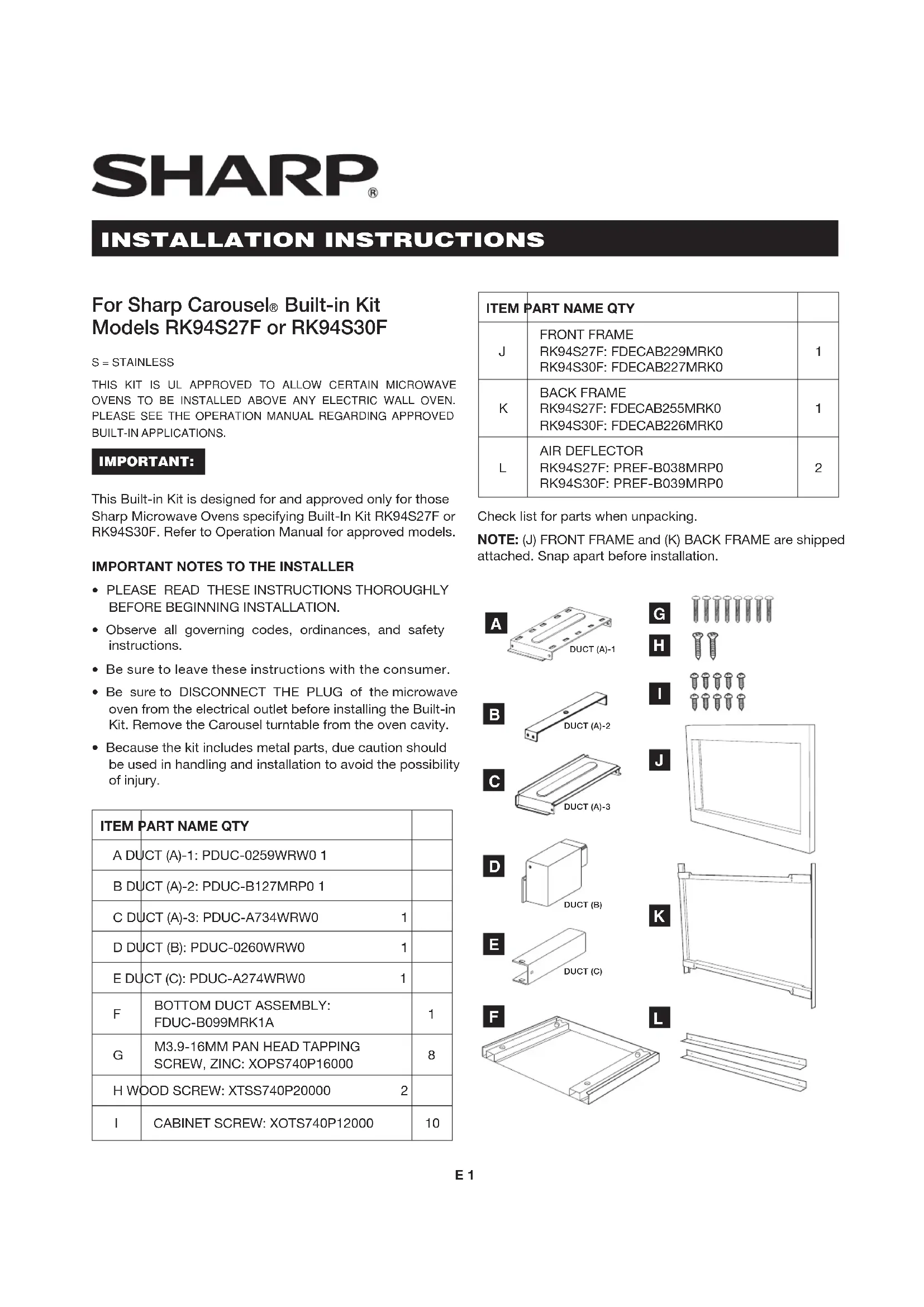
Built-in Kit Models RK94S27F or RK94S30F S = STAINLESS THIS KIT IS UL APPROVED TO ALLOW CERTAIN MICROWAVE OVENS TO BE INSTALLED ABOVE ANY ELECTRIC WALL OVEN. PLEASE SEE THE OPERATION MANUAL REGARDING APPROVED BUILT-IN APPLICATIONS. IMPORTANT: This Built-in Kit is designed for and approved only for those Sharp Microwave Ovens specifying Built-In Kit RK94S27F or RK94S30F. Refer to Operation Manual for approved models.
- Observe all governing codes, ordinances, and safety instructions.
- Be sure to leave these instructions with the consumer.
- Be sure to DISCONNECT THE PLUG of the microwave oven from the electrical outlet before installing the Built-in Kit. Remove the Carousel turntable from the oven cavity.
- Because the kit includes metal parts, due caution should be used in handling and installation to avoid the possibility of injury.
E DUCT (C): PDUC-A274WRW0 1
Check list for parts when unpacking. NOTE: (J) FRONT FRAME and (K) BACK FRAME are shipped attached. Snap apart before installation.
Provide an opening in the wall or cabinet as indicated in Figure 1. The depth should be a minimum of 20
/8" (511.2 mm). If the Depth (E) dimension is greater than 21" (533.4 mm), the outlet location may be in any area on the rear wall. The oor of the opening should be constructed of plywood strong enough to support the weight of the oven (approximately 100 lbs/45 kg) and should be level for proper operation of the oven. NOTE: While the proper function of the oven does not require that the opening be enclosed (with sides, ceiling and rear partition), this may be required by local code, and it is suggested that the local code be checked for any such requirement. The opening in the wall or cabinet must be within the following dimensions, centered horizontal to the cabinet. RK94S27F RK94S30F A 20" (508 mm) 20" (508 mm) B 26
/4" (641.3 mm) E Min. 20
/8" (511.2 mm) F 5" (127 mm) 5" (127 mm) G 10" (254 mm) 10" (254 mm) Outlet should NOT be in the shaded area as indicated on Figure 1. NOTE:
- If the dimension of DEPTH (E) is more than 21" (533.4 mm), the outlet location may be any area on the rear wall.
STEP 2 - EXHAUST DUCT ASSEMBLY INSTALLATION
A. Insert the edge of DUCT (B) into the hold lip of DUCT (C). Secure together by using a SCREW (I) provided in the kit. See Figure 2. DUCT (C) DUCT (B) SCREW (I) FIGURE 2 B. Position DUCT (A)-1 on the top of the oven inserting edge of DUCT (BC) assembly into hole lip of DUCT (A)-
1. Tighten 2 SCREWS (I), securing DUCT (A)-1 to DUCT
(BC) assembly. See Figure 3. SCREW (I)
DUCT (BC) SCREW (I) FIGURE 3 C. Position DUCT (A)-2 on the top of the oven and insert it into the hold lip of DUCT (A)-1. Secure DUCT (A)-2 to DUCT (A)-1 using 2 SCREWS (I) provided. See Figure 4. SCREW (I)SCREW (I)DUCT (A)-2DUCT (A)-1 FIGURE 4 NOTE: Floor of opening should be 90˚ to front cabinet frame.E 3
STANDARD INSTALLATION INSTRUCTIONS
D. Position DUCT (A)-3 on top of the oven and insert it into DUCT (A)-2. Secure DUCT (A)-3 using 3 SCREWS (I) provided. See Figure 5. SCREW (I) SCREW (I) SCREW (I)
FIGURE 5 E. Remove SCREWS from the upper right and left corners at the rear of the oven. Place duct assembly on the top of the unit as shown and secure the duct assembly to the oven using the 2 SCREWS just removed from the oven. See Figure 5A. SCREW SCREW FIGURE 5A
STEP 3 - SURFACE INSTALLATION
A. BOTTOM DUCT ASSEMBLY: Place the Bottom duct in the center of the opening so that gap "A" is equal to gap "B". When the BOTTOM DUCT ASSEMBLY is positioned properly, the front edge of the duct will be ush with the front of the cabinet. Secure with 2 SCREWS (H) See Figure 6. GAP "A" NOTE: CENTER BOTTOM
THE OPENING DETAIL A GAP "B"
BOTTOM DUCT ASSEMBLY
SCREW (H) FIGURE 6 B. CABINET INSTALLATION: Place the oven adjacent to the wall or cabinet opening. Plug the power cord into the electrical outlet. Carefully guide the assembled oven into the prepared opening. Slide the oven on the BOTTOM DUCT ASSEMBLY. See Figure 7. FIGURE 7E 4
STANDARD INSTALLATION INSTRUCTIONS
C. CABINET INSTALLATION: Avoid pinching the cord between the oven and the wall. Adjust the position of the oven so that the feet of the oven are tted into the holes of the BOTTOM DUCT ASSEMBLY. See Figure 8. DUCT RECESS BOTTOM DUCT ASSEMBLY FOOT FIGURE 8 D. DISASSEMBLY: The FRONT FRAME and BACK FRAME come pre-assembled with ball studs engaged in the receivers. Separate the FRONT FRAME from the BACK FRAME. Place the assembly facedown on a protected surface. At the location of the ball stud, insert a athead screwdriver between the FRONT FRAME and the BACK FRAME and gently pry up to disengage the ball stud from the receiver. Repeat for each corner. See Figure 9. FIGURE 9 E. BACK FRAME INSTALLATION: Position BACK FRAME equal space top to bottom, side to side. Mark for 4 holes, center punch and pre-drill with
MOUNTING HOLES MOUNTING HOLES MOUNTING HOLES MOUNTING HOLES FIGURE 10 F. FRONT FRAME INSTALLATION: Place the FRONT FRAME onto the BACK FRAME and align ball studs and receivers. Secure the FRONT FRAME to the BACK FRAME by rmly pushing the FRONT FRAME onto the BACK FRAME, engaging the 4 snap attachments. See Figures 11-12. SNAP ATTACHMENT FIGURE 11 FIGURE 12E 5
The opening in the wall or cabinet must be within the following dimensions: OPENING RK94S27F RK94S30F A 25
/8" (765.2 mm) Height (C) 22
/2" (38.8 mm) G 5" (127 mm) 5" (127 mm) Minimum Depth (I) 20" (508 mm) 20" (508 mm) Outlet should NOT be in the shaded area H as indicated in Figure 1. Mountingcleat
⁄4" (31.8 mm) spaces above and below the trim to allow for necessary intake and exhaust air ow to ensure appliance does not overheat. Do not reduce this spacing as doing so will void the warranty for any issues resulting from a lack of airow. NOTE:
- Please allow minimum 3" (76 mm) wood gap between the microwave oven cutout and the appliance cutout below the microwave oven. See Figure 2.
- The oor of the opening should be constructed of plywood strong enough to support the weight of the oven and oor load (approximately 100 pounds/45 kg). The oor should be level and 90˚ with the face of the cabinet for proper installation and operation of the oven. Be sure to check the local building code as it may require that the opening be enclosed with sides, ceiling and rear partition. The proper functioning of the oven does not require the enclosure.
STEP 2 - EXHAUST DUCT ASSEMBLY INSTALLATION
A. Insert the edge of DUCT (B) into the hold lip of DUCT (C). Secure together by using a SCREW (I) provided in the kit. See Figure 3. DUCT (C) DUCT (B) SCREW (I) FIGURE 3E 6
FLUSH INSTALLATION INSTRUCTIONS
B. Position DUCT (A)-1 on the top of the oven inserting edge of DUCT (BC) assembly into hole lip of DUCT (A)-
1. Tighten 2 SCREWS (I), securing DUCT (A)-1 to DUCT
(BC) assembly. See Figure 4. SCREW (I)
DUCT (BC) SCREW (I) FIGURE 4 C. Position DUCT (A)-2 on the top of the oven and insert it into the hold lip of DUCT (A)-1. Secure DUCT (A)-2 to DUCT (A)-1 using 2 SCREWS (I) provided. See Figure 5. SCREW (I) SCREW (I)
FIGURE 5 D. Position DUCT (A)-3 on top of the oven and insert it into DUCT (A)-2. Secure DUCT (A)-3 using 3 SCREWS (I) provided. See Figure 6. SCREW (I)SCREW (I)SCREW (I)DUCT (A)-3DUCT (A)-2 FIGURE 6 E. Remove SCREWS from the upper right and left corners at the rear of the oven. Place duct assembly on the top of the unit as shown and secure the duct assembly to the oven using the 2 SCREWS just removed from the oven. See Figure 6B. SCREWSCREW FIGURE 6B
STEP 3 - EXHAUST DUCT ASSEMBLY INSTALLATION
A. Place the Exhaust Duct Assembly in the center of the opening. Align the front edge of the duct with the front of the cabinet. Align the front edge of the right side of the duct with the front of the shelf. See Figure 7. B. Secure the Exhaust Duct Assembly with 2 SCREWS (H). See Figure 7. Exhaust duct assembly right side aligns to front edge of shelf Screw HScrew H FIGURE 7E 7
A. Place the oven adjacent to the wall or cabinet opening. Plug the power cord into the electrical outlet. B. Carefully guide the assembled oven into the prepared opening. Slide the oven onto the Exhaust Duct Assembly. See Figure 8. Avoid pinching the cord between the oven and the wall. Adjust the position of the oven so that the feet of the oven are tted into the recesses of the Exhaust Duct Assembly and the door opens properly. See Figure 9. Screw D Screw D FIGURE 8 Exhaust duct assembly Foot Duct recess FIGURE 9 C. DISASSEMBLY: The FRONT FRAME and BACK FRAME come pre-assembled with ball studs engaged in the receivers. Separate the FRONT FRAME from the BACK FRAME. Place the assembly facedown onto a protected surface. At the location of the ball stud, insert a athead screwdriver between the FRONT FRAME and the BACK FRAME and gently pry up to disengage the ball stud from the receiver. Repeat for each corner. See Figure 10. FIGURE 10 D. BACK FRAME INSTALLATION: Position BACK FRAME equal space top to bottom, side to side. Mark for 4 holes on the installed wood cleats, center punch and pre-drill with
⁄16” drill bit. Secure frame with 4 SCREWS (G). See Figure 11. Equal gap top, bottomEqual gapside to sideMounting holesMounting holesMounting holesMounting holesScrew GScrew GScrew GScrew G FIGURE 11E 8 E. Install Air Deectors top and bottom. Center (left and right) the Air Deectors above and below the installed BACK FRAME. Secure Air Deectors with 4 SCREWS (G). See Figure 12. Mark holes and pre-drill the wood cleats with
⁄16” drill bit. FIGURE 12 F. FRONT FRAME INSTALLATION: Place the FRONT FRAME onto the BACK FRAME and align ball studs and receivers. Secure the FRONT FRAME to the BACK FRAME by rmly pushing the FRONT FRAME onto the BACK FRAME, engaging the 4 snap attachments. See Figures 13-14. Snap Attachment FIGURE 13 FIGURE 14
34-1/2” MIN. FLOOR FLOOR