
80RDE - Fridge Marvel - Free user manual and instructions
Find the device manual for free 80RDE Marvel in PDF.

| Product Type | Drawer Refrigerator (Refrigerated Drawer Cabinet) |
| Brand | Marvel |
| Model | 80RDE |
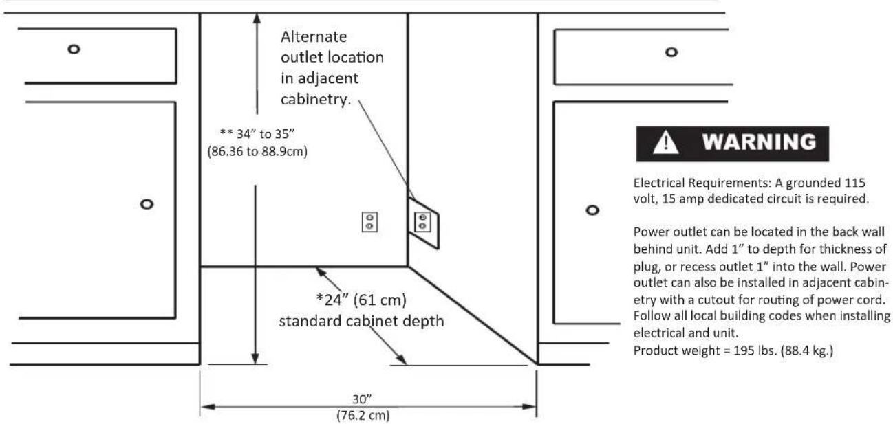
| Width | 30 in (76.2 cm) |
| Adjustable Height | 33.75 in to 34.75 in (85.7 to 88.3 cm) |
| Power Supply | 115 V, 15 A, dedicated circuit, grounded outlet |
| Temperature Range | 33 °F to 47 °F (1 °C to 8 °C) |
| Number of Drawers | 2 |
| Control Display | Sentry System™ with digital display |
| Functions | Temperature adjustment, Sabbath mode, alarms (drawer open, temperature, power outage), LED interior lighting |
| Maintenance | Clean condenser annually, front grille 1 to 2 times per year |
| Interior Cleaning | Mild soapy solution, no abrasive products |
| Safety | Anti-tip device, unplug before maintenance, no extension cord |
| Warranty | 1 year parts and labor, then 4 years parts for cooling system |
| Available Options | E-Z Store storage system, stainless steel drawer dividers |
Frequently Asked Questions - 80RDE Marvel
User questions about 80RDE Marvel
0 question about this device. Answer the ones you know or ask your own.
Ask a new question about this device
Download the instructions for your Fridge in PDF format for free! Find your manual 80RDE - Marvel and take your electronic device back in hand. On this page are published all the documents necessary for the use of your device. 80RDE by Marvel.
USER MANUAL 80RDE Marvel
Refrigerated Printer Models
60RDE
6ORDEP
80RDE
6ORDE (Outdoor)
MARVEL
CONTENTS
Unpacking your refrigerated drawer unit. 3
Removing the packaging. 3
Warranty Registration.. 3
Installing your refrigerated drawer unit. 4
Selecting the location 4
Outdoor Installation 4
Cabinet Clearances 4
Leveling legs. 4
5
Installing the anti tip device. 6
Energy Saving Tips 6
Dimensions Indoor Model 60RDE 60RDEP. 7
Recommended Rough in Opening Dimensions Indoor Model 60RDE 60RDEP. 7
Dimensions Indoor Model 60RDE Overlay Door. 8
Recommended Rough in Opening Dimensions Indoor Model 60RDE Overlay Door. 8
Dimensions Outdoor Model 6ORDE. 9
Recommended Rough in Opening Dimensions Outdoor Model 6ORDE. 9
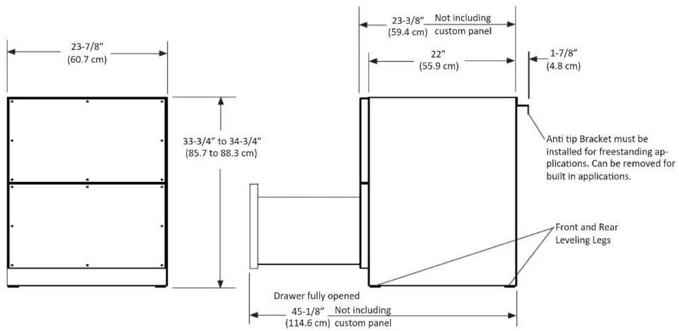
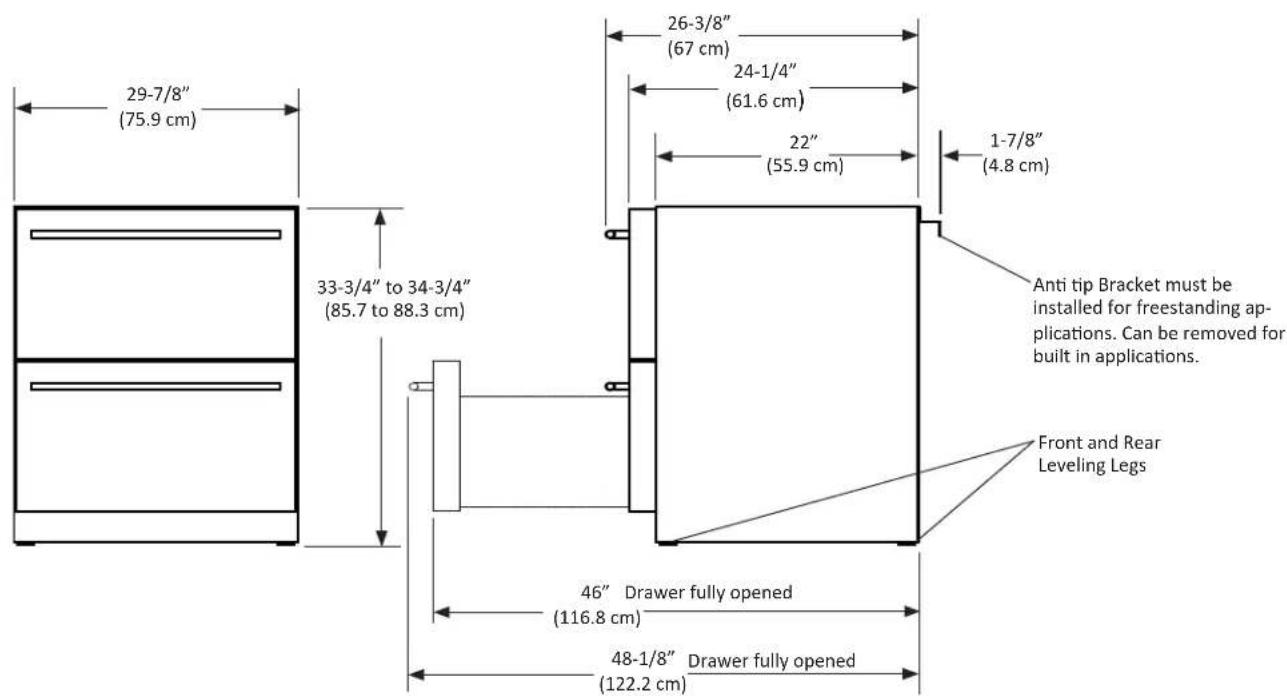
Dimensions Indoor Model 80RDE. 10
Recommended Rough in Opening Dimensions Indoor Model 80RDE. 10
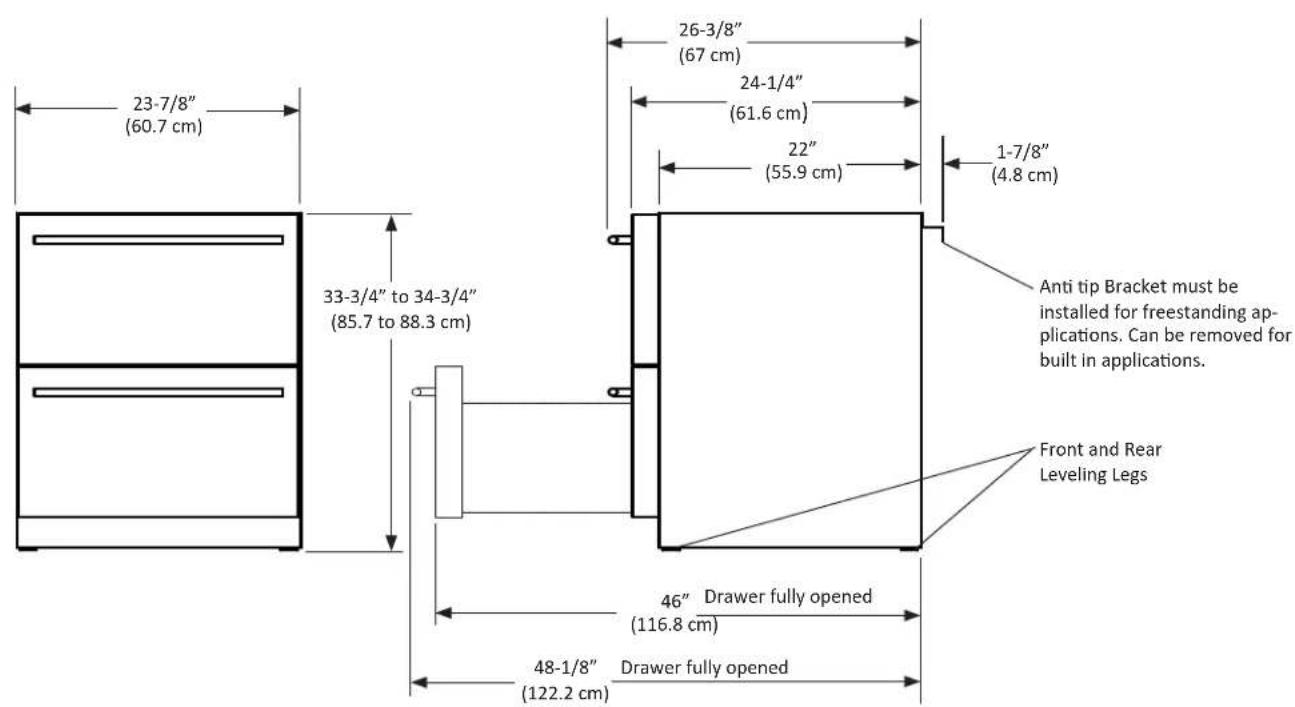
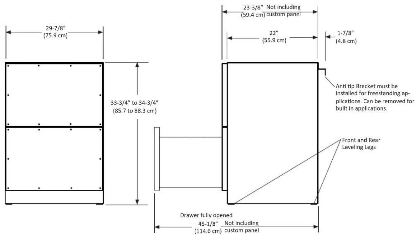
Dimensions Indoor Model 80RDE Overlay Door. 11
Recommended Rough in Opening Dimensions Indoor Model 80RDE Overlay Door. 11
Full Overlay Panel Installation Instructions. 12
Using Your Refrigerated Drawers 14
Starting Your Appliance 14
-
Set Your Temperature Mode 14
-
Set the Desired Temperature 143
Load Your Appliance. 14
Interior Light 14
- Defrost Cycle 143
Sabbath Mode. 14
Warning Alarms. 14
Sentry System™ Quick Reference. 15
Care and Cleaning. 17
E-Z Store Storage System (Optional) 17
Drawer Dividers (Optional) 17
Troubleshooting Guide 18
Obtaining Service. 18
Household Product Warranty. 19


AGA MARVELis committed to building a quality product in an environmentally friendly manner. Our processes are tightly controlled and closely monitored. We have achieved certifications in ISO 9001 for quality assurance, ISO 14001 for environmental management, and OHSAS 18001 for occupational health and safety from Lloyd's Register Quality Assurance.
Important Safety Instructions
Warnings and safety instructions appearing in this guide are not meant to cover all possible conditions and situations that may occur. Common sense, caution, and care must be exercised when installing, maintaining, or operating this appliance.
Recognize Safety Symbols, Words, and Labels.

CAUTION
CAUTION-Hazards or unsafe practices which could result in personal injury or property or product damage.

WARNING
WARNING-Hazards or unsafe practices which could result in personal injury.
NOTE
NOTE-Important information to make a problem free installation.
Remove Packaging
Your refrigerated drawers have been packed for shipment with all parts that could be damaged by movement securely fastened. Cut the banding material at the bottom of the carton, unfold the cartoning at the bottom and remove the carton from the appliance. Remove the plastic bag, styrofoam corner posts and any tape holding the drawers closed and internal components in place.
The owners manual is shipped inside the drawer in a plastic bag along with the warranty registration card.
Important
Keep your carton packaging until your refrigerated drawers have been thoroughly inspected and found to be in good condition. If there is damage, the packaging will be needed as proof of damage in transit. Afterwards please dispose of all items responsibly in particular the plastic bags which can be a suffocation hazard.
Note to Customer
This merchandise was carefully packed and thoroughly inspected before leaving our plant. Responsibility for its safe delivery was assumed by the retailer upon acceptance of the shipment. Claims for loss or damage sustained in transit must be made to the retailer.
DO NOT RETURN DAMAGED MERCHANDISE TO THE MANUFACTURER - FILE THE CLAIM WITH THE RETAILER.
NOTE
If the unit was shipped or has been laying on its back for any period of time allow the refrigerator to sit upright for a period of at least 24 hours before plugging in. This will assure oil returns to the compressor. Plugging the refrigerator in immediately may cause damage to internal parts.
Warranty Registration
It is important you send in your warranty registration card immediately after taking delivery of your refrigerated drawers.
The following information will be required when registering your unit.
Model Number
Serial Number
Date of Purchase
Dealer's name and address
The model number and serial number can be found on the serial plate which is located on the bottom of the cabinet liner in the left front corner. Open the bottom drawer to full extension to view it. See Figure 1.
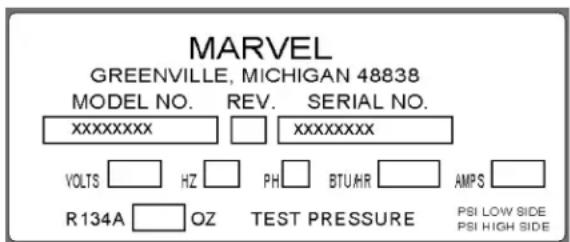
Figure 1

CAUTION
Help Prevent Tragedies
Child entrapment and suffocation are not problems of the past. Junked or abandoned refrigerators are still dangerous - even if they sit out for "just a few days".
If you are getting rid of your old refrigerator, please follow the instructions below to help prevent accidents.
Before you throw away your old refrigerator or freezer:
- Take off the doors or remove the drawers.
- Leave the shelves in place so children may not easily climb inside.
Select Location
The proper location will ensure peak performance of your appliance. We recommend a location where the unit will be out of direct sunlight and away from heat sources. To assure your product performs to specifications the recommended installation location temperature range is from 55 to 100^ (13 to 38^ ).

CAUTION
Outdoor Installation
Only the 6ORDE model is suitable for outdoor installations.
Building codes may require a ground fault circuit interrupter electrical receptacle to supply electrical power to the refrigerator for outdoor applications, (see "Electrical Connection" section).
Do not install in an environment where the unit will be exposed to direct sun exposure as this may result in unsatisfactory performance.
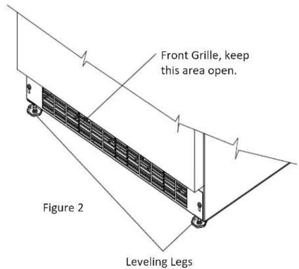
Cabinet Clearance
Ventilation is required from the bottom front section of the unit. Keep this area open and clear of any obstructions. Adjacent cabinets and counter top can be installed around the unit as long as the grille and drawer access remain unobstructed.

CAUTION
FrontGrille
Do not obstruct the front grille. The openings within the front grille allow air to flow through the condenser heat exchanger. Restrictions to this air flow will result in increased energy usage and loss of cooling capacity. For this reason it is important this area to not be obstructed and the grille openings kept clean. AGA MARVEL does not recommend the use of custom made grilles as air flow may be restricted because of inadequate openings. (See Figure 1).
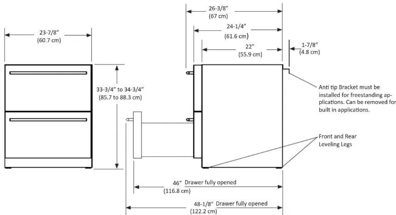
Leveling Legs
Adjustable legs at the front and rear corners of the unit should be set so the unit is firmly positioned on the floor and level from side to side and front to back. The overall height of your Marvel refrigerator may be adjusted from 33 - 3 / 4'' (85.7cm) with the leveling legs turned in, and up to 34 - 3 / 4'' (88.3cm) with the leveling legs extended. The 30'' wide product (80RDE) has a center leg at the rear of the cabinet that must also be used to stabilize the cabinet. (See Figure 3).
To adjust the leveling legs, place the refrigerator on a solid surface and protect the floor beneath the legs to avoid scratching the floor. With the assistance of another person, lean the refrigerator back to access the front leveling legs. Raise or lower the legs to the required dimension by turning the legs. Repeat this process for the rear by tilting the refrigerator forward using caution to prevent the door from opening. On a level surface check the refrigerator for levelness and adjust accordingly.
The front grille (toe kick) screws may be loosened and adjusted to the desired height. When adjustment is complete tighten the two toe kick screws. (See Figure 4).
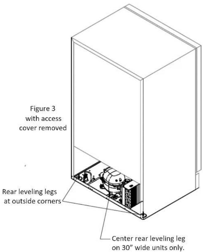
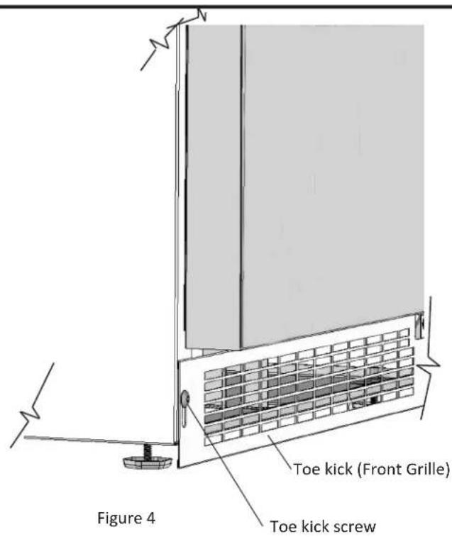
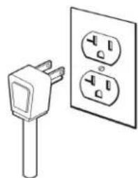
Figure 5
The unit must be installed according to your local building codes and ordinances.
NOTE
Ground Fault Circuit Interrupters (GFCI) are prone to nuisance tripping which will cause the unit to shut down. GFCI's are generally not used on circuits which power equipment that must run unattended for long periods of time, unless required to meet local building codes and ordinances.

CAUTION
- Do not splash or spray water from a hose on the refrigerator! Doing so may cause an electrical shock, which may result in severe injury or death.
- This unit should not, under any circumstances, be installed to an un-grounded electrical supply.
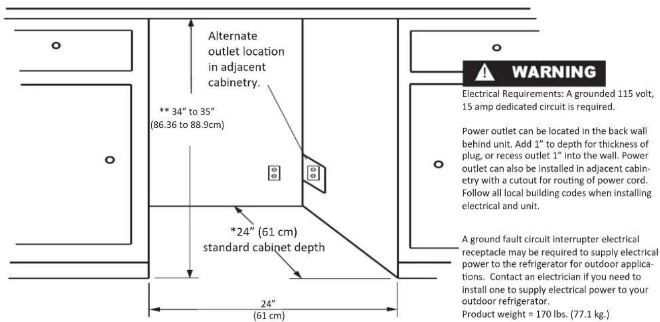
Electrical Connection
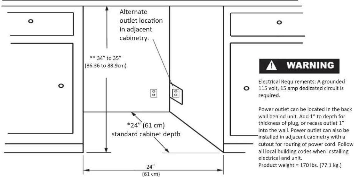
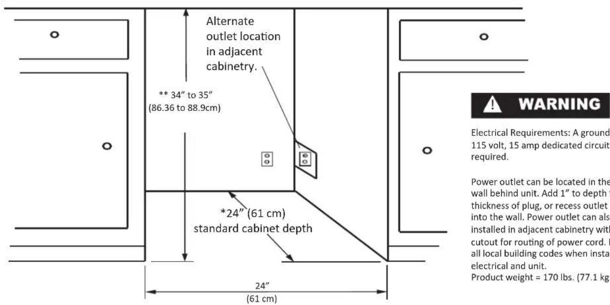
A grounded 115 volt, 15 amp dedicated circuit is required.
This product is factory equipped with a power supply cord that has a three-pronged, grounded plug. It must be plugged into a mating grounding type receptacle in accordance with the National Electrical Code and applicable local codes and ordinances (see Figure 3). If the circuit does not have a grounding type receptacle, it is the responsibility and obligation of the customer to provide the proper power supply. The third ground prong should not, under any circumstances, be cut or removed.

CAUTION
Do not use an extension cord with this appliance.
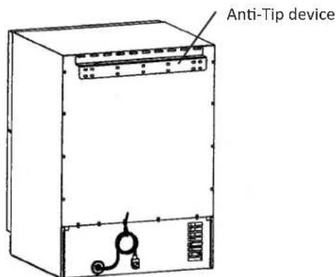
Figure 6

CAUTION
Anti - Tip Device
A cabinet "anti-tip" device is mounted to the back of your refrigerated drawer unit. If your installation is a built-in under counter application with a counter top directly above the unit this item can be removed, it does not need to be applied. If your unit is a freestanding application with no counter top directly above the top of the unit, you must apply this feature to prevent the unit from tipping forward when the drawers are pulled out. The anti-tip device is installed on the back of the unit. The anti-tip device reduces the chance of personal injury as well as property damage when properly installed between the back of the unit and the adjacent wall. Please see the following instructions for installing the anti-tip device.
- Push the unit against the wall so the anti-tip bracket is flush to the wall adjacent to the back panel. Level the unit with the leveling legs provided in the cabinet bottom. (See Leveling Legs on page 4).
- Using a pencil and the bracket as a template, trace the bracket on the wall, making sure 2 of the screw holes are aligned with a stud in the wall.
- Pull the unit away from the wall.
- Remove the screws that connect the upper and lower sections of the anti-tip bracket.
- Place the bracket on the wall and mark and drill 316 dia. Pilot holes for the provided 14 lag screws. Mount the lower section to the wall with the 14 lag screws.
- Move the unit into place aligning the screw holes between the upper and lower brackets and secure with the screws removed in step 4.
The following suggestions will minimize the cost of operating your refrigeration appliance.
- Do not install your appliance next to a hot appliance, (cook- er, dishwasher, etc.). heating air duct, or other heat sources.
- Install product out of direct sunlight.
- Assure the toe grille vents at front of unit beneath drawer is not obstructed and kept clean to allow ventilation for the refrigeration system to expel heat.
- Plug your appliance into a dedicated power circuit. (Not shared with other appliances).
- When initially loading your new product, or whenever large quantities of warm contents are placed within refrigerated storage compartment, minimize drawer openings for the next 12 hours to allow contents to pull down to compartment set-point temperature.
- Maintaining a relatively full storage compartment will require less appliance run time than an empty compartment.
- Assure drawer closing is not obstructed by contents stored in your appliance.
- Allow hot items to reach room temperature before placing in product.
- Minimize drawer openings and duration of drawer openings.
- Use the warmest temperature control set-point that meets your personal preference and provides the proper storage for your stored contents.
- When on vacation or away from home for extended periods, set the appliance to warmest acceptable temperature for the stored contents.
- Set the control to the "off" position if cleaning the unit requires the drawer to be open for an extended period of time.
- Annually clean condenser heat exchange coil located in machine compartment underneath unit, (see "Care and Cleaning" page 17).
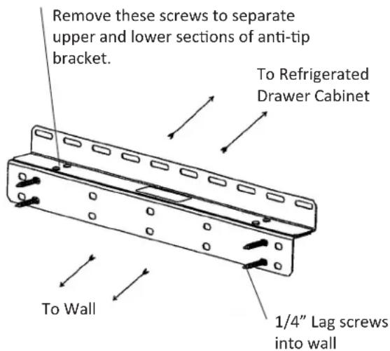
Figure 7
RECOMMENDED ROUGH IN OPENING DIMENSIONS, 60RDE AND 60RDEP
Depth dimension may very depending on each individual installation.
* Minimum rough in opening required is to be larger than the adjusted height of the cabinet.
RECOMMENDED ROUGH IN OPENING DIMENSIONS,INDOOR MODEL 60RDE OVERLAY DOOR
Depth dimension may very depending on each individual installation.
* Minimum rough in opening required is to be larger than the adjusted height of the cabinet.
RECOMMENDED ROUGH IN OPENING DIMENSIONS, OUTDOOR MODEL 6ORDE
Depth dimension may very depending on each individual installation.
* Minimum rough in opening required is to be larger than the adjusted height of the cabinet.
RECOMMENDED ROUGH IN OPENING DIMENSIONS, INDOOR MODEL 80RDE
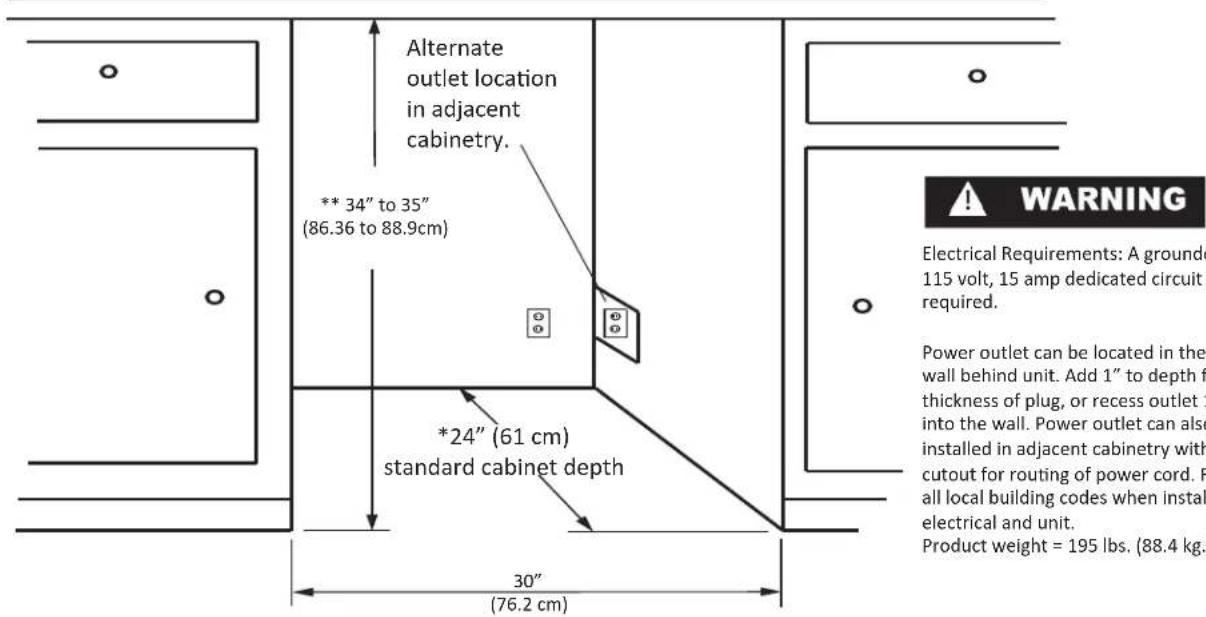
Depth dimension may very depending on each individual installation.
* Minimum rough in opening required is to be larger than the adjusted height of the cabinet.
RECOMMENDED ROUGH IN OPENING DIMENSIONS, INDOOR MODEL 80RDE OVERLAY DOOR
Depth dimension may very depending on each individual installation.
* Minimum rough in opening required is to be larger than the adjusted height of the cabinet.

CAUTION
Determine Wood Screw Requirements
- A #10 pan head wood screw should be used to properly secure the overlay panel. A total of 8 screws per drawer for the 60 unit and 10 screws per drawer for the 80 unit will be required. (See Figure 11). Necessary screws are supplied with unit.
- Use only pan head screws.
- If your overlay panel is thinner than 5/8 (15.9 mm) you will need to purchase shorter screws.
Step 1: Remove Drawers from unit.
- Remove drawer from the unit. Begin by pulling out the drawer. Locate the drawer lock which can be found on the outside of the cabinet slide (see Figure 7). Push the back of the drawer lock forward and then down, releasing the drawer from the cabinet slide (see Figure 8). Repeat this on the opposite side of the drawer. Lift the drawer up from the slides at a 90 degree angle to fully extricate the drawer from the cabinet (See Figure 9).
- Remove the gasket from the drawer front. (See Figure 10). Do this by pulling the gasket out of the channel that holds it to the drawer front. This will expose the clearance holes for mounting the overlay panel. (See Figure 14).
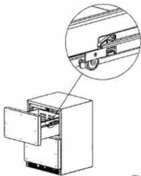
Figure 8
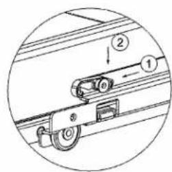
Figure 9
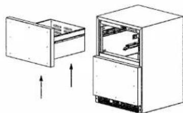
Figure 10
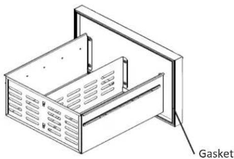
Figure 11
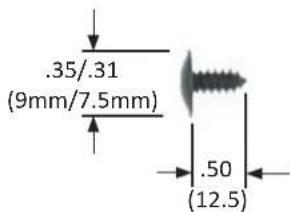
Figure 12
Step 2: Size the Overlay Panel
Cut the overlay panel to the dimensions shown below. Use Figure 12 for the 60RDE Printer, and Figure 13 for the 80RDE printer.
This is also a convenient time to locate and drill the holes for your handle. Most often the handle is to match that of the surrounding cabinetry. If your handle attaches from the back-side of the custom panel, locate the mounting holes while the panel is attached to the drawer and cabinet. After the panel is removed from the drawer, drill the mounting holes from the front, to the recommended diameter of the handle manufacturer. Counter bore the back-side of the panel so the screw heads do not interfere with the surface of the drawer.
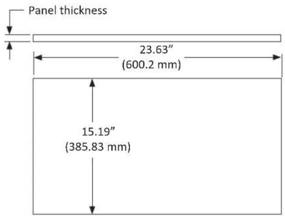
Figure 13 Face of 60RDE Overlay Panel
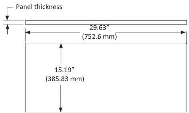
Figure 14 Face of 80RDE Overlay Panel
Step 3: Attach the Overlay Panel to the Printer
- Set the overlay panel on drawer front face and align edges. (See Figure 14 below). Clamp panel in position and mark pilot hole locations. Pick the required pilot hole size from "Table A" below and drill the pilot holes ensuring not to drill all the way through the overlay panel.
Table A: Pilot Hole Drill Sizes for Wood Screws
| Material Type #8 Wood Screw |
| Hardwood 1/8 Dia. Pilot Hole |
| Softwood 7/64 Dia. Pilot Hole |
- Insert wood screws through clearance holes and tighten to secure overlay panel.
- Reinstall gasket into channel. Make sure the corners are fully inserted.
Step 4: Reinstall the Drawers
- Fully extend drawer slides and place drawer on slides. Be sure that drawer sits evenly on both slides.
- Lock drawers into drawer slides. Push drawer locks down and then back to re lock the drawer into the slide.

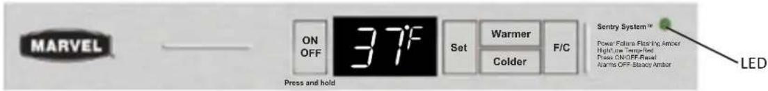
Figure 16
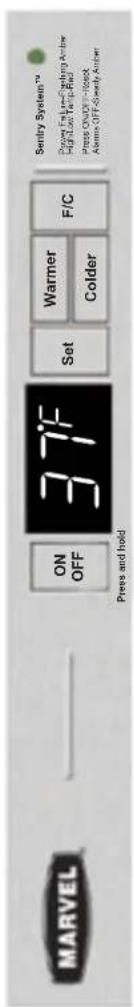
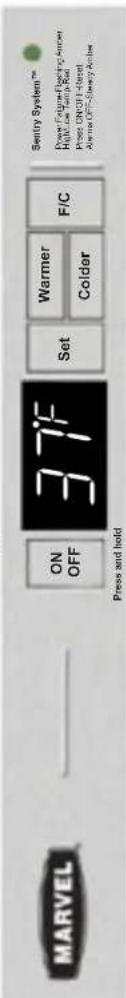
Start Your Appliance
Your refrigerated drawers have been fitted with a Sentry System™ refrigeration monitor. It is located at the top front of the cabinet and can be accessed by opening the top drawer. Your appliance will start upon initial plug-in. On start the Sentry System™ monitor will flash amber. This is normal. Press the "ON/OFF" button and the appliance resets and the LED turns green. (Refer to Figure 15 above). To turn the unit ON/OFF, press and hold the "ON/OFF" key for a minimum of 5 seconds.
Set Your Temperature Mode
This product can display either Fahrenheit or Celsius. To do so, press the "F/C" button on the display panel to change from one to the other.
Set the desired temperature
The available temperature range of the unit is from 33^ to 47^ (1^ to 8^) . This range allows flexibility of temperature preferences and provides the ideal storing and serving temperatures. The temperature set point can be lowered or raised by first pushing the "SET" button on the display pad. A "SET" icon will be displayed in the temperature display. Pressing and releasing either the "WARMER" or "COLDER" buttons located on the display pad will raise or lower the set temperature by one (1) degree at a time. As with any refrigeration product, there will be slight temperature variance at different locations within the cabinet.
Load Your Appliance
Load your appliance with your desired items. Please note that it may take up to 24 hours for your refrigerator to reach the desired temperature once loaded. This will primarily depend on the amount of contents loaded into the refrigerator and the amount of opening and closings of the drawers. Consider this when initially loading the drawers. Best results will be obtained by first allowing the drawers to "pull down" to your set temperature before loading the drawers.
Interior Light
The upper and lower interior lights make it easy to view your food and beverages. The light will always come on when either drawer is opened, except when unit is in Sabbath Mode.
Defrost Cycle
In order to maintain optimal performance, your refrigerator must periodically enter a defrost cycle to clear frost buildup. During the defrost cycles, the display will show DEF, and changes to setpoint and ^ F / C setting may not be made.
Sabbath Mode
Your refrigerated drawers are equipped with a Sabbath Mode feature. By activating this mode, you will be disabling all displays, audible alarms and lights. To activate the Sabbath Mode, press and hold the "SET" button while pressing the "°F/C" button four (4) times within seven (7) seconds. To disable the Sabbath Mode, repeat the process. The Sabbath Mode will deactivate automatically after 72 hours.
Warning Alarms
The Sentry System™ monitor will let you know if your unit is not functioning properly for the following reasons. Door ajar, high or low temperature, and power failure. These alarms are explained below.
Door Ajar Alarm
If the drawer has been left open for over five (5) minutes, the alarm will sound and the LED will flash green. This will stop as soon as the drawer is closed, or can be reset by pressing the "ON/OFF" button.
High and Low Temperature
If your unit reaches temperatures outside normal operating temperatures for your set point for more than one (1) hour, an alarm will sound and the LED will flash red. This will warn you that your contents have seen temperatures that may not be conducive for long-term storage. This alarm can be reset by pressing the "ON/OFF" button.
Power Failure
If your unit experiences a power failure, the LED will flash amber until the alarm is reset by pressing the "ON/OFF" button.
Reset Alarms
Press the "ON/OFF" button for approximately one (1) second. This will reset all audible and display alarms when the button is released.
Enable/Disable Sentry System™ Alarms
Press and hold the "SET" key for five (5) seconds to enable or disable the Sentry System™ alarms. LED will display a steady green when enabled or a steady amber when disabled.
Quick Reference Guide
The quick reference guide on page 15 and 16 can be removed from this manual and retained near the appliance for quick access to the Sentry System™ functions.
Sentry System™ "Basic" Function "Quick" Reference
Note: All keypad presses are confirmed with an audible tone when released.
| Function Function | Access Control Confirmation / Comment | |
| Turn Unit On & Off | Pressing and holding the "On/Off" key for five seconds will turn the unit "ON" or "Off". | The display will be blank when the refrigeration system is off. Lights will still function, but will time-out in 15 minutes after each activation if drawer is left open, to prevent overheating. |
| Adjust and View Temperature set-point | To adjust the temperature set-point, press the "SET" key and current set-point will be displayed. Use the "WARMER" or "COLDER" keys to adjust set-point temperature. | "SET" will appear in temperature display when in set-point mode. "SET" mode will automatically time-out in ten (10) seconds if no keypad activity occurs, or you may exit "SET" mode by pressing the "SET" key.a second time. |
| Display "Actual" Temperature | The display represents real time monitoring. Some temperature fluctuation around the set-point will be noticeable as the refrigeration system cycles on and off to maintain the desired temperature. | Temperature variation in "compartment" air, above and below set-point, is a normal effect of refrigeration system cycling on and off. Stored items will not experience the full temperature swing of the compartment air due to the dampening effect of their thermal mass. |
| Select "F or ℃ Display | Pressing the "F/℃" key will toggle the display between Fahrenheit and Centigrade temperature display. | i.e. 55°F = 13°C |
| Sabbath Mode | Press and hold the "SET" key while pressing the "F/℃" key four (4) times in seven (7) seconds. | The display will flash "SA" seven (7) times, then the unit will enter Sabbath Mode. The display, audible alarms, LED, and lights will be disabled. Sabbath Mode will automatically time-out in 72 hours., or can be exited by repeating the enabling process. |
| Sentry System™ alarms | No action required. System monitoring is automatically enabled unless system has been disabled (see below). | Sentry System™ LED displays a steady green when Sentry System™ is enabled. |
| Drawer Ajar Alarm | No action required if Sentry System™ is enabled. | Audible alarm will sound 3 times every 30 seconds, the LED will flash green. Close drawer to reset alarm. |
| High/Low Temp Alarm | No action is required if Sentry System™ is enabled. NOTE: This alarm may occur when changing set-points and/or high usage, this is normal. | Alarm will sound 6-times every minute and LED will flash red if product temperature excursions occur for a duration outside acceptable limits. |
| Power Failure Alarm | No action required if Sentry System™ is enabled. NOTE: Alarm will occur upon initial installation, since unit was run at the factory to verify quality, this is normal. | LED will flash amber whenever power is interrupted to unit. There is no audible signal. Press ON/OFF button to reset alarm. |
| Reset Alarms | Close drawer to reset "DOOR AJAR" alarm. Press the "ON/OFF" key to reset all other alarms. | Note that although pressing the "ON/OFF" key resets the alarms, the alarm will resume if the "alarm condition" still exists. |
| Enable / Disable Sentry System™alarms | Press and hold the "SET" key for five (5) seconds to enable or disable the Sentry System™ alarms. | LED displays a steady green when alarms are enabled. LED displays a steady amber when they are disabled. |
Sentry System™ "Troubleshooting" Function "Quick" Reference
Note: All keypad presses are confirmed with an audible tone when released.
| Function Function | Access Control Confirmation / Comment | |||||
| Show Room Mode | Enable the showroom mode by pressing and holding the “ON/OFF” key while performing a “Power On Reset” (POR). i.e. disconnect and reconnect the power supply to the unit. Exit Showroom Mode by initiating a POR only. | Show Room Mode will disable the refrigeration system and fans while allowing the internal lights, display, and user interface panel to function. Lights will time-out after 15 minutes of continuous on-time while in Show Room Mode as a safety feature. The 15 minute light on time can be reactivated by closing and opening the door or by pressing the “LIGHT” key. | ||||
| Error Codes | E1 Compressor fault, (high/low amps) | |||||
| E2 Condenser fan motor fault, (high/low amps) | ||||||
| E3 Evaporator thermistor “sensor B” fault, (out of range) | ||||||
| E4 Display thermistor “sensor A” fault, (out of range) | ||||||
| Please call a qualified service technician if any of these codes are displayed. | ||||||
| Service Diagnostics | To enter and exit Service Diagnostics Mode, press and hold the “WARMER” key while pressing the “COLDER” key four (4) times in five (5) seconds. Service Diagnostics Mode will automatically exit after five (5) minutes of no keypad entry. Display Error Code Reference: The microprocessor in the control continually monitors critical refrigeration system components for proper operation. If component parameters exceed normal operation specifications, the display will automatically flash the respective error code as follows: | Service Diagnostics Mode enables service technicians to identify the firmware and software versions, test status of “model specific” system components and sensors, and change state of components where applicable, (i.e. -compressor “ON/OFF” etc.). While in Service Diagnostics Mode, tests are incremented by pressing the “SET” key and specific component state can be changed to “on” or “off” by pressing the “WARMER” or “COLDER” keys respectively. The following component tests are available: Available Status Indicators | ||||
| Test # | Component Description OK Off/ | Open | On/Shorted | |||
| 0 Temperature Sensor, Upper 0-00 01 | ||||||
| 1 Temperature Sensor, Lower 1-10 11 | ||||||
| 2 Compressor n/a 20 21 | ||||||
| 3 Interior / Ice Maker Fan n/a 30 31 | ||||||
| 4 Reverse Gas Solenoid n/a 40 41 | ||||||
| 5 Condenser Fan | n/a | 50 | 51 | |||
| 6 Million Heater | n/a 60 €1 | |||||
| 7 Door A Sense | n/a | 70 | 71 | |||
| 8 Door B Sense | n/a 80 €1 | |||||
| 9 Door C Sense | n/a | 90 | 91 | |||
| NOTE: The Door Sense is located between the Upper Compartment Display and the “ON/OFF” key and can be tested with any magnet. Door sense “C” (Test #9) is in the menu but not available on drawer units. | ||||||
Condenser
The condenser underneath the cabinet does not require frequent cleaning; however, satisfactory cooling depends on adequate ventilation over this heat exchanger. It is recommended to annually clean the condenser by vacuuming and brushing. To access the condenser, the unit must be pulled out from the installation, and the lower machine compartment access cover removed.

WARNING
Disconnect the power cord before cleaning the condenser.
Be sure that nothing obstructs the required air flow openings in front of the cabinet. At least once or twice a year, brush or vacuum lint and dirt from the front grille area (see page 4).
Cabinet
The painted cabinet can be washed with either a mild soap and water and thoroughly rinsed with clear water. NEVER use abrasive scouring cleaners.
Interior
Wash interior compartment with mild soap and water. Do NOT use an abrasive cleaner, solvent, polish cleaner or undiluted detergent.
Care of Unit
- Avoid leaning on the drawer fronts, you may bend the drawer slides or tip the unit.
- Exercise caution when sweeping, vacuuming or mopping near the front of the unit. Damage to the grille can occur.
- Periodically clean the interior of the unit as needed.
- Periodically check and/or clean the front grille as needed.
AVAILABLE OPTIONS FOR YOUR MARVEL DRAWER REFRIGERATOR
E-Z Stor Storage System
Removable stainless steel bins with clear plastic lids can be moved to prep, cook, or serving areas as desired. Available for 60RDE and 80RDE upper and lower drawers.
P/N 42245441 for 60 upper or lower drawers
P/N 42245442 for 80 upper drawer
P/N 42245443 for 80 lower drawer
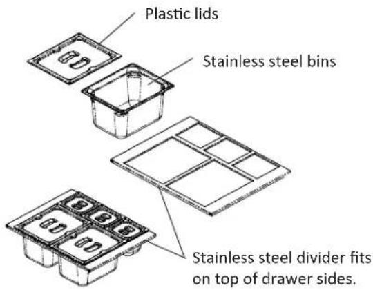
Figure 17 E-Z-Store Storage System
For further information on available options visit the AGA MARVEL web site at www.agamarvel.com or contact your AGA MARVEL dealer.
NOTE
When installing these options in the drawers the standard drawer divider will have to be removed.
Drawer Dividers
Fully adjustable stainless steel drawer dividers allow for optimum storage and organization of storage space.
P/N 42245444 for 60RDE upper drawer
P/N 42245445 for 60RDE lower drawer
P/N 42245446 for 80RDE upper drawer
P/N 42245447 for 80RDE lower drawer
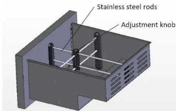
Figure 18
Drawer Dividers
Before You Call for Service
If the unit appears to be malfunctioning, read through this manual first. If the problem persists, check the troubleshooting guide below. Locate the problem in the guide and refer to the cause and its remedy before calling for service. The problem may be something very simple that can be solved without a service call. However, it may be required to contact your dealer or a qualified service technician.
If Service is Required:
- If the product is within the first year warranty period please contact your dealer or call AGA MARVEL Customer Service at 800.223.3900 for directions on how to obtain warranty coverage in your area.
- If the product is outside the first year warranty period, AGA MARVEL Customer Service can provide recommendations of service centers in your area. A listing of authorized service centers is also available at www.agamarvel.com under the service and support section.

WARNING
Electrocution Hazard - Never attempt to repair or perform maintenance on the unit until the main electrical power has been disconnected. Turning the unit control "OFF" does not remove electrical power from the units wiring.
- In all correspondence regarding service, be sure to give the model number, serial number, located on your products serial plate, and proof of purchase.
- Try to have information or description of nature of the problem, how long the unit has been running, the room temperature, and any additional information that may be helpful in quickly solving the problem.
Table B is provided for recording pertinent information regarding your product for future reference.
Table B
| For Your Records | |
| Date of Purchase | |
| Dealer's name | |
| Dealer's Address | |
| Dealer's City | |
| Dealer's State | |
| Dealer's Zip Code | |
| Appliance Serial Number | |
| Appliance Model Number | |
| Date Warranty Card Sent (Must be within 10 days of purchase). | |
| Problem Possible Cause | Remedy | |
| Unit not cold enough. • Control set too warm. • Content temperature not stabilized. • Excessive usage or prolonged drawer openings. • Airflow to front grille blocked. •Drawer gasket not sealing properly. | too warm. •Content temperature not stabilized. •Excessive usage or prolonged drawer openings. •Airflow to front grille blocked. •Drawer gasket not sealing properly. | Adjust temperature colder, (See "Set the desired temperature" on page 14). Allow 24 hours for temperature to stabilize. •Allow temperature to stabilize for at least 24 hours. •Airflow must not be obstructed to front grille. See "clearances" on page 4. •Adjust or replace drawer gasket. |
| Unit too cold. • Control set too cold | •Drawer gasket not sealing properly. | Adjust temperature warmer. (See page 14, "set the desired temperature"). Allow 24 hours for temperature to stabilize. •Adjust or replace drawer gasket. |
| No interior light in drawer compa- ments. | •Failed LED interior light assembly. •Contact a qualified AGA MARVEL service technician. | |
| Light will not go out when drawer is closed. | •Drawer not activating light switch. •Unit not level, level unit, (See page 4, "level- ing legs"). | |
| Noise or Vibration. • Unit not level. | •Level unit, see "Leveling Legs" on page 4. | |
| Unit will not run. • Unit turned off. | •Power cord not plugged in. •No power at outlet. | Turn unit on. See "Start your Appliance" on page 14. •Plug in power cord. •Check house circuit. |
Entire Product
Limited One Year Parts and Labor Warranty
AGA MARVEL warrants that it will supply all necessary parts and labor to repair or replace in the end user's home or office, any component which proves to be defective in material or workmanship, subject to the condition and exclusions stated below, for a period of one year from the date of purchase by the end user.
Additional Second Through Fifth Year Limited Parts Only Warranty
During the four years following expiration of the one year limited warranty, AGA MARVEL will supply replacement parts for the hermetically sealed refrigeration system which consists of the compressor, condenser, drier, accumulator, bypass valve, connecting tubing and the evaporator that are proven to be defective due to workmanship or materials subject to the conditions and exclusions below.
The above warranties do not cover:
- Shipping costs of replacement parts or returned defective parts.
- Customer education or instructions on how to use the appliance.
- Any content loss due to product failure.
- Removal or installation of product.
Nor do the above warranties cover failure of this product or its components due to:
- Transportation or subsequent damages.
- Commercial use or use other than normal household or small office.
- Improper installation, misuse, abuse, accident or alteration, use of wiring not conforming to electrical codes, low or high voltages, failure to provide necessary maintenance, or other unreasonable use.
Parts or Service
Not Supplied or Designated by AGA MARVEL
The above warranties also do not apply if:
- The original bill of sale, deliver date, or serial number cannot be verified.
Defective parts are not returned for inspection if so requested by AGA MARVEL. - The refrigeration equipment is not in the possession of the original end use purchaser.
The warranties set forth herein are the only warranties extended by AGA MARVEL. Any implied warranties, including the implied warranty of merchantability, are limited to the duration of these express warranties. In no event shall AGA MARVEL be liable for any consequential or incidental damages or expenses resulting from breach of these or any other warranties, whether express or implied.
Some states do not allow the exclusion or limitation of consequential damages or a limitation on how long an implied warranty lasts, so the above exclusion or limitation may not apply to you. This warranty gives you specific legal rights and you may have other rights that may vary from state to state.
No person, firm, or corporation is authorized to make any other warranty or assume any other obligation for AGA MARVEL. These warranties apply only to products used in any of the fifty states of the United States and the District of Columbia.
To obtain performance of this warranty, report any defects to:
AGAMARVEL
1260 E. VanDeinse St.
Greenville MI 48838
Phone: 800.223.3900
MARVEL
www.agamarvel.com
AGAMARVEL
1260 E. VanDeinse St.
Greenville MI 48838
800.223.3900
41011754-EN Rev P
10/31/11
- CONTENTS
- Important Safety Instructions
- Recognize Safety Symbols, Words, and Labels.
- CAUTION
- WARNING
- NOTE
- Remove Packaging
- Important
- Note to Customer
- Warranty Registration
- Help Prevent Tragedies
- Select Location
- Outdoor Installation
- Cabinet Clearance
- FrontGrille
- Leveling Legs
- Electrical Connection
- Anti - Tip Device
- The following suggestions will minimize the cost of operating your refrigeration appliance.
- RECOMMENDED ROUGH IN OPENING DIMENSIONS,INDOOR MODEL 60RDE OVERLAY DOOR
- Determine Wood Screw Requirements
- Step 1: Remove Drawers from unit.
- Step 2: Size the Overlay Panel
- Step 3: Attach the Overlay Panel to the Printer
- Step 4: Reinstall the Drawers
- Start Your Appliance
- Set Your Temperature Mode
- Set the desired temperature
- Load Your Appliance
- Interior Light
- Defrost Cycle
- Sabbath Mode
- Warning Alarms
- Door Ajar Alarm
- High and Low Temperature
- Power Failure
- Reset Alarms
- Enable/Disable Sentry System™ Alarms
- Quick Reference Guide
- Sentry System™ "Basic" Function "Quick" Reference
- Sentry System™ "Troubleshooting" Function "Quick" Reference
- Condenser
- Cabinet
- Interior
- Care of Unit
- AVAILABLE OPTIONS FOR YOUR MARVEL DRAWER REFRIGERATOR
- E-Z Stor Storage System
- Drawer Dividers
- Before You Call for Service
- If Service is Required:
- Entire Product
- Limited One Year Parts and Labor Warranty
- Additional Second Through Fifth Year Limited Parts Only Warranty
- Parts or Service
- Not Supplied or Designated by AGA MARVEL
- AGAMARVEL
Brand : Marvel
Model : 80RDE
Category : Fridge