
MPRO6WCM - Wine cellar Marvel - Free user manual and instructions
Find the device manual for free MPRO6WCM Marvel in PDF.

| Product Type | Refrigerated Wine Cellar |
| Brand | Marvel |
| Model | MPRO6WCM |
| Bottle Capacity | Approximately 32 standard bottles (4 sliding shelves of 8 bottles each + lower basket) |
| Dimensions (H x W) | 77.0 cm x 59.5 cm (30 5/16" x 23 7/16") |
| Weight | 59.1 kg (130 lbs) |
| Electrical Supply | 115 V, 15 A, dedicated circuit, grounded plug |
| Temperature Range | 4 °C to 18 °C (40 °F to 65 °F) |
| Door Type | Glass or custom overlay panel |
| Temperature Control | MicroSentry™ digital display with precise adjustment |
| Interior Lighting | LED (replacement by qualified technician) |
| Shelves | 4 sliding shelves for single-layer bottle storage |
| Alarms | Door open (>5 min) and temperature sensor failure (code E1) |
| Cleaning | Front grille to be dusted regularly; interior with mild soapy solution |
| Warranty | 1 year parts and labor, then an additional 5 years on sealed cooling system (parts only) |
| Installation | Built-in under counter or freestanding; adjustable leveling legs; ventilation through front grille |
| Recommended Ambient Temperature | 13 °C to 38 °C (55 °F to 100 °F) |
| Certifications | ISO 9001, ISO 14001, OHSAS 18001 |
Frequently Asked Questions - MPRO6WCM Marvel
User questions about MPRO6WCM Marvel
0 question about this device. Answer the ones you know or ask your own.
Ask a new question about this device
Download the instructions for your Wine cellar in PDF format for free! Find your manual MPRO6WCM - Marvel and take your electronic device back in hand. On this page are published all the documents necessary for the use of your device. MPRO6WCM by Marvel.
USER MANUAL MPRO6WCM Marvel
Installation Operation and Maintenance Instructions
Refrigerated Wine Cellars
30WCM (Marvel) 61WCM (Marvel) MPRO3WCM (Professional) MPRO6WCM (Professional)
Note: Wine Cellars are designed exclusively for the storage of wine. Wine Cellars cannot attain storage temperatures suitable for fresh food storage.


CONTENTS
Unpacking your wine cellar.... 3
Removing interior packaging.... 3
Warranty Registration 3
Installing your wine cellar.... 4
Selecting the location.... 4
Cabinet Clearances 4
Leveling legs 4
Electrical Connection 5
Using Your MicroSentry™ Control.... 6
Dimensions for 30WCM glass door....7
Recommended Rough in Opening Dimensions for 30WCM glass door....7
Dimensions for 30WCM glass overlay door....8
Recommended Rough in Opening Dimensions for 30WCM glass overlay door....8
Dimensions for 30WCM solid overlay door....9
Recommended Rough in Opening Dimensions for 30WCM solid overlay door....9
Dimensions for MPRO3WCM glass door.... 10
Recommended Rough in Opening Dimensions for MPRO3WCM glass door.... 10
Dimensions for 61WCM glass door 11
Recommended Rough in Opening Dimensions for 61WCM glass door.... 11
Dimensions for 61WCM glass overlay door.... 12
Recommended Rough in Opening Dimensions for 61WCM glass overlay door.... 12
Dimensions for 61WCM solid overlay door.... 13
Recommended Rough in Opening Dimensions for 61WCM solid overlay door.... 13
Dimensions for MPRO6WCM glass door.... 14
Recommended Rough in Opening Dimensions for MPRO6WCM glass door.... 14
Full Overlay Panel Installation Instructions.... 15
Features 18
Energy Saving Tips 21
Care and Cleaning 21
Cleaning the cabinet.... 21
Cleaning the interior.... 21
Cleaning the wine shelves.... 21
Cleaning the door gasket.... 21
Replacing the light bulb.... 21
Troubleshooting Guide.... 22
Obtaining Service 22
Household Product Warranty.... 23


AGA MARVELis committed to building a quality product in an environmentally friendly manner. Our processes are tightly controlled and closely monitored. We have achieved certifications in ISO 9001 for quality assurance, ISO 14001 for environmental management, and OHSAS 18001 for occupational health and safety from Lloyd's Register Quality Assurance.
Important Safety Instructions
Warnings and safety instructions appearing in this guide are not meant to cover all possible conditions and situations that may occur. Common sense, caution, and care must be exercised when installing, maintaining, or operating this appliance.
Recognize Safety Symbols, Words, and Labels.

WARNING
WARNING-Hazards or unsafe practices with high probability of personal injury or property / product damage.

CAUTION
CAUTION-Hazards or unsafe practices which could result in personal injury or property or product damage.
NOTE
NOTE-Important information to help assure a problem free installation and operation.
Remove Interior Packaging
Your wine cellar has been packed for shipment with all parts that could be damaged by movement securely fastened. Remove internal packing materials and any tape holding internal components in place. The owners manual is shipped inside the product in a plastic bag along with the warranty registration card, and other accessory items.
Important
Keep your carton and packaging until your wine cellar has been thoroughly inspected and found to be in good condition. If there is damage, the packaging will be needed as proof of damage in transit. Afterwards please dispose of all items responsibly in particular the plastic bags which can be a suffocation hazard.
Note to Customer
This merchandise was carefully packed and thoroughly inspected before leaving our plant. Responsibility for its safe delivery was assumed by the retailer upon acceptance of the shipment. Claims for loss or damage sustained in transit must be made to the retailer.
DO NOT RETURN DAMAGED MERCHANDISE TO THE MANUFACTURER - FILE THE CLAIM WITH THE RETAILER.

CAUTION
If the unit was shipped or has been laying on its back for any period of time allow the wine cellar to sit upright for a period of at least 24 hours before plugging in. This will ensure oil returns to the compressor. Plugging the wine cellar in immediately may cause damage to internal parts.
Warranty Registration
It is important you send in your warranty registration card immediately after taking delivery of your wine cellar.
The following information will be required when registering your unit.
Service Number
Serial Number
Date of Purchase
Dealer's name and address
The service number and serial number can be found on the serial plate which is located inside the wine cellar on the left side toward the top of the liner. See Figure 1.
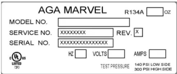
Figure 1

CAUTION
Help Prevent Tragedies
Child entrapment and suffocation are not problems of the past. Junked or abandoned refrigerators are still dangerous - even if they sit out for “just a few days”.
If you are getting rid of your old refrigerator, please follow the instructions below to help prevent accidents.
Before you throw away your old refrigerator or freezer:
• Take off the doors or remove the drawers.
- Leave the shelves in place so children may not easily climb inside.
Select Location
The proper location will ensure peak performance of your appliance. We recommend a location where the unit will be out of direct sunlight and away from heat sources. To ensure your product performs to specifications the recommended installation location temperature range is from 55 to 100°F (13 to 38°C).
Cabinet Clearance
Ventilation is required from the bottom front section of the unit. Keep this area open and clear of any obstructions. Adjacent cabinets and counter top can be installed around the unit as long as the front grille remains unobstructed.

CAUTION
Front Grille
Do not obstruct the front grille. The openings within the front grille allow air to flow through the condenser heat exchanger. Restrictions to this air flow will result in increased energy usage and loss of cooling capacity. For this reason it is important this area to not be obstructed and the grille openings kept clean. AGA MARVEL does not recommend the use of custom made grilles as air flow may be restricted because of inadequate openings. (See Figure 2).
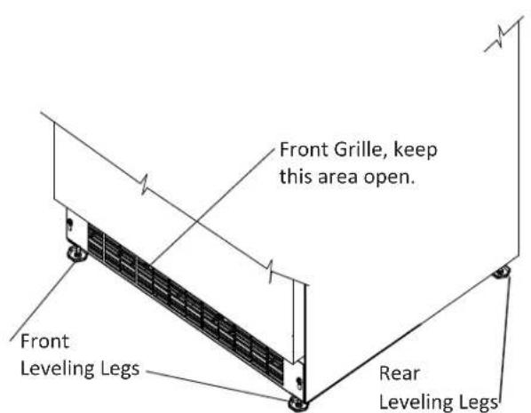
Figure 2
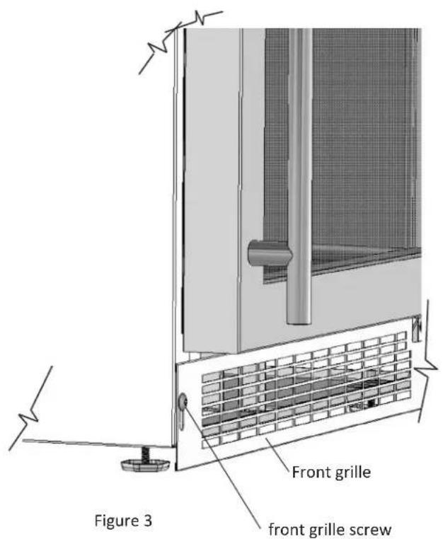
Leveling Legs
Adjustable legs at the front and rear corners of the unit should be set so the unit is firmly positioned on the floor and level from side to side and front to back. The overall height of your Marvel refrigerator may be adjusted from 33 ^3/4 " (85.7cm) with the leveling legs turned in, and up to 34 ^3/4 " (88.3cm) with the leveling legs extended.
To adjust the leveling legs, place the refrigerator on a solid surface and protect the floor beneath the legs to avoid scratching the floor. With the assistance of another person, lean the refrigerator back to access the front leveling legs. Raise or lower the legs to the required dimension by turning the legs. Repeat this process for the rear by tilting the refrigerator forward using caution to prevent the door from opening. On a level surface check the refrigerator for levelness and adjust accordingly.
The front grille screws may be loosened and the front grille adjusted to the desired height. When adjustment is complete tighten the two front grille screws. (See Figure 3).

WARNING
- Do not splash or spray water from a hose on the wine cellar. Doing so may cause an electrical shock, which may result in severe injury or death.
- This unit should not, under any circumstances, be installed to an un-grounded electrical supply.
Electrical Connection:
A grounded 115 volt, 15 amp dedicated circuit is required.
This product is factory equipped with a power supply cord that has a three-pronged, grounded plug. It must be plugged into a mating grounding type receptacle in accordance with the National Electrical Code and applicable local codes and ordinances (see Figure 4). If the circuit does not have a grounding type receptacle, it is the responsibility and obligation of the customer to provide the proper power supply. The third ground prong should not, under any circumstances, be cut or removed.

CAUTION
Electrical Extension cords should not be used. They can be hazard-
ous and cause deficient operation. The wall receptacle should be located near the product and be a polarized type with adequate ground protection. The product must be installed to your local building codes and ordinances.
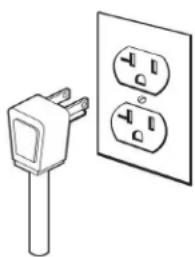
natural_image
Simple line drawing of an electrical plug and two socket (no text or symbols)Figure 4
NOTE
Ground Fault Circuit Interrupters (GFCI) are prone to nuisance tripping which will cause the unit to shut down. GFCI's are generally not used on circuits with powered equipment that must run unattended for long periods of time, unless required to meet local building codes and ordinances.
Starting your refrigerator
Plug the refrigerator power cord into a wall outlet. Your refrigerator will begin cooling after power is applied.
If your refrigerator does not start, check that the refrigerator is turned on and the set temperature is cold enough.
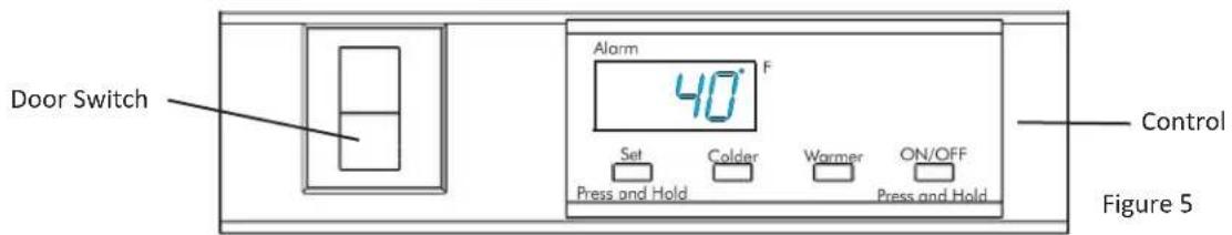
Turning your refrigerator ON or OFF
If the refrigerator is on, the refrigerator temperature will be shown on the display. To turn the refrigerator off, press and hold the "ON/OFF" button for three (3) seconds. "OFF" will appear on the display.
If the refrigerator is not on, "OFF" will be shown on the display. To turn the refrigerator on, press and hold the "ON/OFF" button for three (3) seconds. The refrigerator temperature will be shown on the display.
Set temperature
To set the refrigerator temperature, press and hold the "SET" button. When the "SET" button is pressed, the display will show the set temperature. While holding the "SET" button, press the "WARMER" or "COLDER" buttons to adjust set temperature.
Refrigerator operation
The available temperature range of the refrigerator is 40^ to 65^ ( 4^ to 18^ C).
It may take up to 24 hours for your refrigerator to reach desired temperature. This will depend on amount of content loaded and number of door opening and closings.
For best results allow refrigerator to "pull down" to desired set temperature before loading. Once contents are loaded, allow at least 48 hours for temperature to stabilize before making any adjustments to the set temperature.
Alarms
Your MicroSentry™ refrigerator control will monitor refrigerator function and alert you with a series of audible and visual alarms.

- Door Ajar Alarm: If the door has been left open for over five (5) minutes, the alarm will sound in one (1) second intervals. The
display panel will flash "do" and the Alarm LED located at the top left of the display below the word "Alarm" will be illuminated. This will stop as soon as the door is closed.

• Temperature Sensor Fault: If the controller detects that the temperature sensor is not properly functioning, a temperature
sensor alarm will sound in one (1) second intervals. "E1" will flash on the display panel and the Alarm LED located at the top left of the display below the word "Alarm" will be illuminated. Please call AGA MARVEL Customer Service or your dealer if this error code is displayed.
Alarm Mute
Press any key to mute the audible portion of an alarm.
NOTE-This action will only mute the alarm. If the condition that caused the alarm continues, the alarm code will continue to flash and will sound for 20 seconds every 60 minutes.

ROUGH IN OPENING DIMENSIONS, FOR 30WCM GLASS DOOR


CAUTION
Electrical Requirements: A grounded 115 volt, 15 amp dedicated circuit is required.
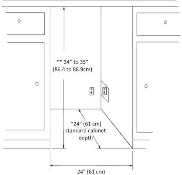
Power outlet can be located in the back wall behind unit. Add 1" to depth for thickness of plug, or recess outlet 1" into the wall. Power outlet can also be installed in adjacent cabinetry with a cutout for routing of power cord. Follow all local building codes when installing electrical and unit. Product weight = 100 lbs. (45.5 kg.)
* Depth dimension may vary depending on each individual installation.
** Minimum rough in opening required is to be larger than the adjusted height of the cabinet.
* To face of door with-out custom panel
ROUGH IN OPENING DIMENSIONS FOR 30WCM AND MPRO3WCM
GLASS OVERLAY DOOR

CAUTION
Electrical Requirements: A grounded 115 volt, 15 amp dedicated circuit is required.
Power outlet can be located in the back wall behind unit. Add 1" to depth for thickness of plug, or recess outlet 1" into the wall. Power outlet can also be installed in adjacent cabinetry with a cutout for routing of power cord. Follow all local building codes when installing electrical and unit. Product weight = 100 lbs. (45.5 kg.)
* Depth dimension may vary depending on each individual installation.
** Minimum rough in opening required is to be larger than the adjusted height of the cabinet.
* To face of door without custom panel
ROUGH IN OPENING DIMENSIONS FOR 30WCM SOLID OVERLAY DOOR

CAUTION
Electrical Requirements: A grounded 115 volt, 15 amp dedicated circuit is required.
Power outlet can be located in the back wall behind unit. Add 1" to depth for thickness of plug, or recess outlet 1" into the wall. Power outlet can also be installed in adjacent cabinetry with a cutout for routing of power cord. Follow all local building codes when installing electrical and unit.
Product weight = 100 lbs. (45.5 kg.)
* Depth dimension may vary depending on each individual installation.
** Minimum rough in opening required is to be larger than the adjusted height of the cabinet.
ROUGH IN OPENING DIMENSIONS, FOR MPRO3WCM GLASS DOOR

CAUTION
Electrical Requirements: A grounded 115 volt, 15 amp dedicated circuit is required.
Power outlet can be located in the back wall behind unit. Add 1" to depth for thickness of plug, or recess outlet 1" into the wall. Power outlet can also be installed in adjacent cabinetry with a cutout for routing of power cord. Follow all local building codes when installing electrical and unit. Product weight = 100 lbs. (45.5 kg.)
* Depth dimension may vary depending on each individual installation.
** Minimum rough in opening required is to be larger than the adjusted height of the cabinet.

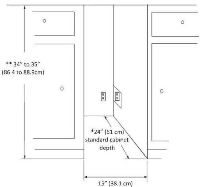
ROUGH IN OPENING DIMENSIONS FOR 61WCM GLASS DOOR


CAUTION
Electrical Requirements: A grounded 115 volt, 15 amp dedicated circuit is required.
Power outlet can be located in the back wall behind unit. Add 1" to depth for thickness of plug, or recess outlet 1" into the wall. Power outlet can also be installed in adjacent cabinetry with a cutout for routing of power cord. Follow all local building codes when installing electrical and unit. Product weight = 130 lbs. (59.1 kg.)
* Depth dimension may vary depending on each individual installation.
** Minimum rough in opening required is to be larger than the adjusted height of the cabinet.
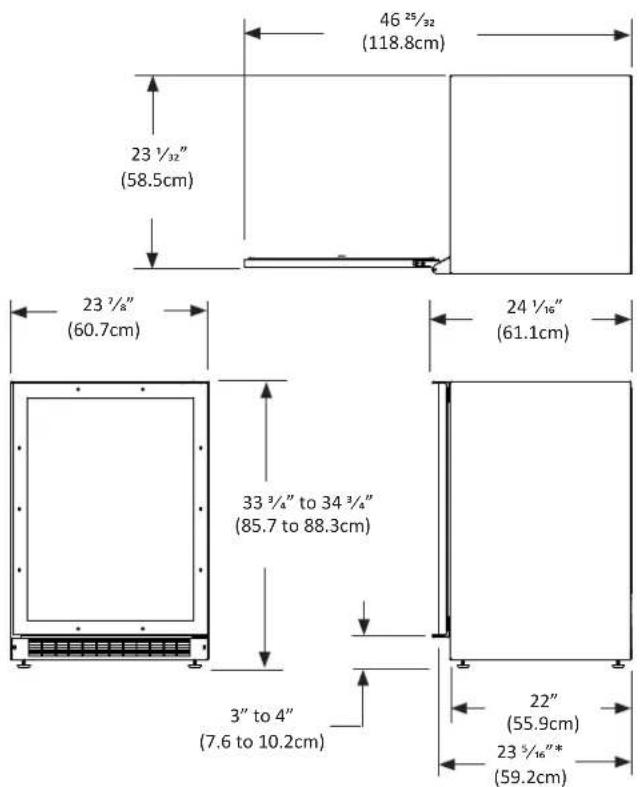
* To face of door with-out custom panel
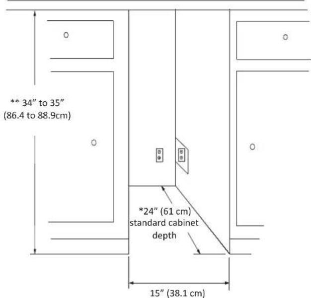
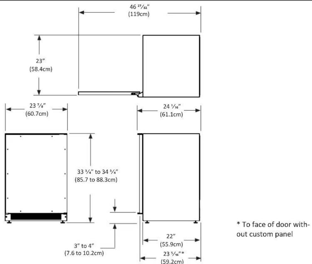
ROUGH IN OPENING DIMENSIONS FOR 61WCM AND MPRO6WCM
GLASS OVERLAY DOOR
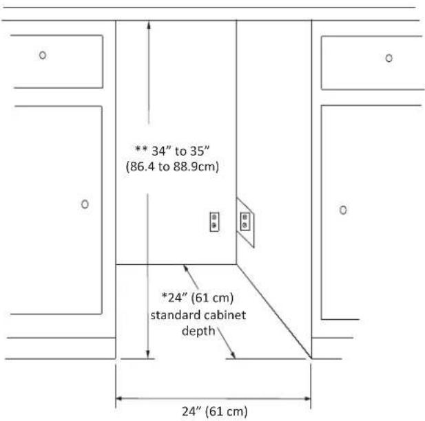

CAUTION
Electrical Requirements: A grounded 115 volt, 15 amp dedicated circuit is required.
Power outlet can be located in the back wall behind unit. Add 1" to depth for thickness of plug, or recess outlet 1" into the wall. Power outlet can also be installed in adjacent cabinetry with a cutout for routing of power cord. Follow all local building codes when installing electrical and unit. Product weight = 130 lbs. (59.1 kg.)
* Depth dimension may vary depending on each individual installation.
** Minimum rough in opening required is to be larger than the adjusted height of the cabinet.
ROUGH IN OPENING DIMENSIONS FOR 61WCM SOLID OVERLAY DOOR

CAUTION
Electrical Requirements: A grounded 115 volt, 15 amp dedicated circuit is required.
Power outlet can be located in the back wall behind unit. Add 1" to depth for thickness of plug, or recess outlet 1" into the wall. Power outlet can also be installed in adjacent cabinetry with a cutout for routing of power cord. Follow all local building codes when installing electrical and unit. Product weight = 130 lbs. (59.1 kg.)
* Depth dimension may vary depending on each individual installation.
** Minimum rough in opening required is to be larger than the adjusted height of the cabinet.
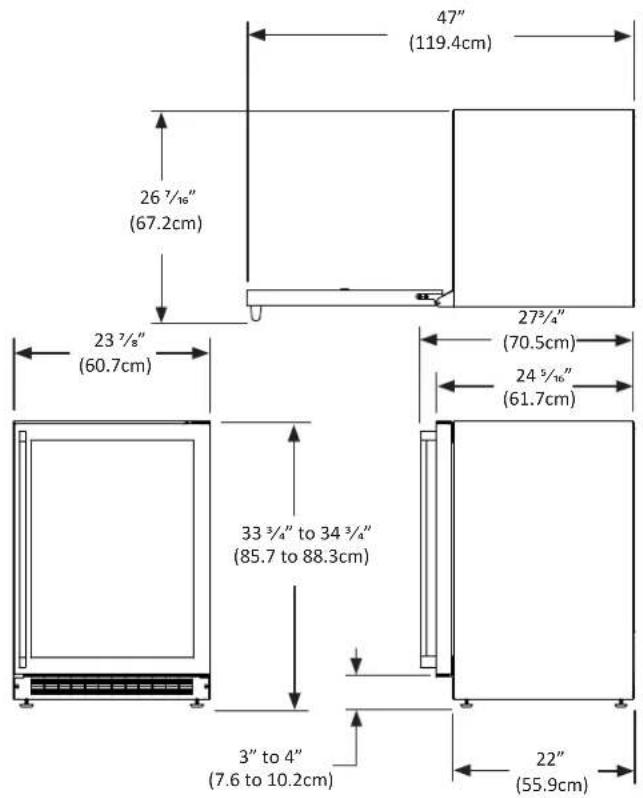
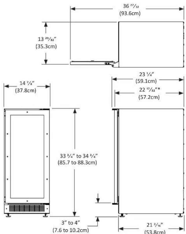
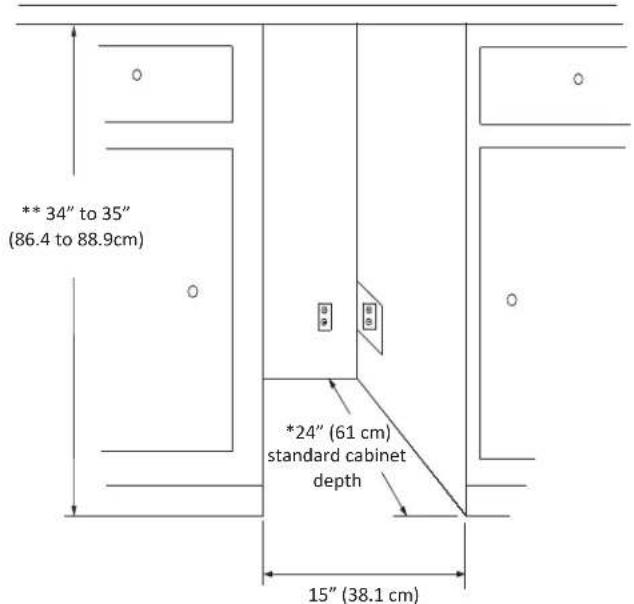
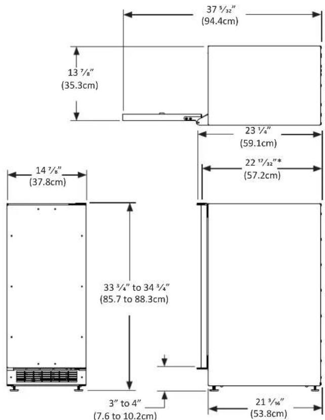
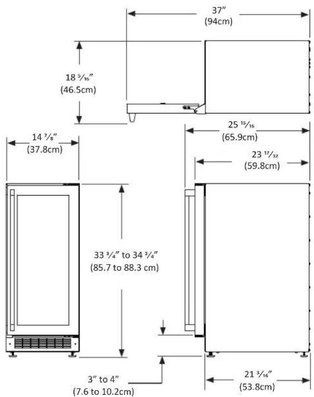
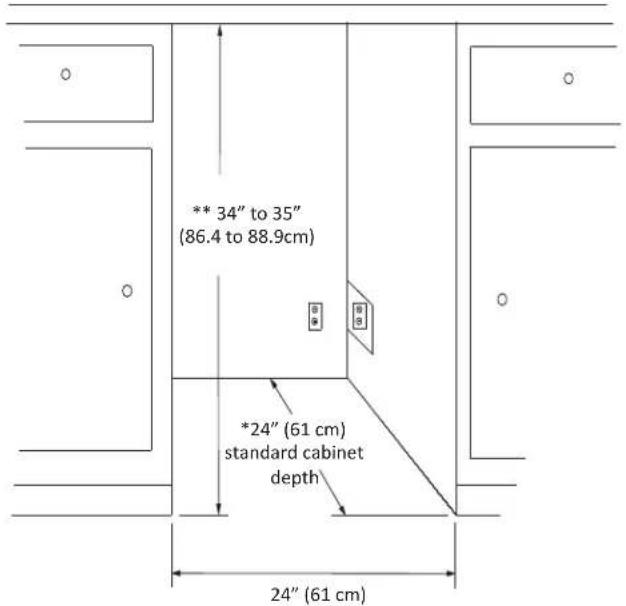
ROUGH IN OPENING DIMENSIONS FOR MPRO6WCM GLASS DOOR

CAUTION
Electrical Requirements: A grounded 115 volt, 15 amp dedicated circuit is required.
Power outlet can be located in the back wall behind unit. Add 1" to depth for thickness of plug, or recess outlet 1" into the wall. Power outlet can also be installed in adjacent cabinetry with a cutout for routing of power cord. Follow all local building codes when installing electrical and unit. Product weight = 130 lbs. (59.1 kg.)
* Depth dimension may vary depending on each individual installation.
** Minimum rough in opening required is to be larger than the adjusted height of the cabinet.

CAUTION
Step 1: Verify door alignment
Verify that the door is aligned correctly with the cabinet prior to fabricating the custom panel. Failure to do so could result in mis-alignment of the custom panel with the hinge bracket. The door should be parallel to the sides and top of the refrigerator. If alignment is necessary the door may be adjusted by loosening the 2 screws which secure the upper and/or lower hinge adapter brackets located on the top and bottom of the door, and adjusting the door side to side. Use a 5/32'' allen wrench for this procedure. (See Figure 6 below). When finished aligning the door, tighten the screws securely.
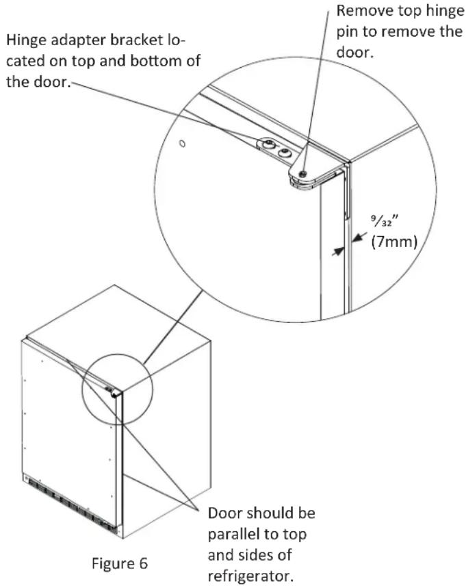
Step 2: Remove door
Remove the top hinge pin from the hinge with an 18 " allen wrench. Remove the door by angling the top of the door outward and lifting the door off the bottom hinge.
(See detail in Figure 6).
Step 3: Remove gasket
Lay the door on its front being careful not to scratch it. To gain access to the screw holes remove the door gasket by peeling up and out of the channel.
Step 4: Cut overlay panel
Depending on the wine cellar model cut the overlay panel to the dimensions shown. Use Figure 7 and Table A for solid door models or use Figure 8 and Table B for glass door models.
NOTE
For overlay with lock option panel thickness to be 34 " (19mm) maximum to 58 " (16mm) minimum.

CAUTION
Weight of the overlay panel should not exceed 20 pounds (9.1 kilograms).
NOTE
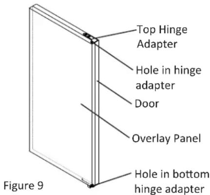
For the door to close properly, it is necessary to maintain a minimum space of 932 " (7mm) between the door and cabinet flange (See Figure 6). This space can be adjusted by adjusting the top and bottom hinge adapter brackets.
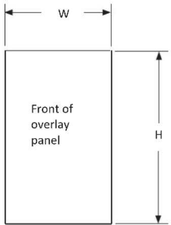
Figure 7 Solid Door Models
| Model W | H | |
| 30WCM | 14^5/8" (37.1cm) | 30^5/16" (77cm) |
| 61WCM | 23^5/8" (60cm) | 30^5/16" (77cm) |
Table A Solid Door Models
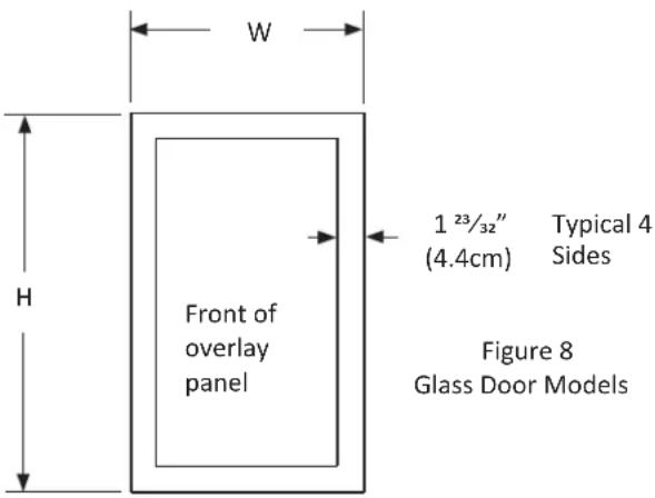
| Model W H | ||
| 30WCM MPRO3WCM | 14^5/16" (36.4cm) | 30^5/16" (77cm) |
| 61WCM MPRO6WCM | 23^7/16" (59.5cm) | 30^5/16" (77cm) |
Table B Glass Door Models
Step 5: Drill hinge clearance holes in overlay panel
Set the overlay panel on the door front, align the edges, and clamp together. Clamp the panel firmly but be careful not to damage the door or the panel. Mark center of hinge adapter hole on wood panel, top and bottom. (See Figure 9.) Remove wood panel from door and drill 5/16'' (8mm) diameter clearance holes into the overlay panels 3/4'' (20mm) deep. These will be clearance holes for the top and bottom hinge pins.
This is also a convenient time to locate and drill the holes for your handle. Most often the handle is to match that of the surrounding cabinetry. If your handle attaches from the back-side of the custom panel, locate the mounting holes while the panel is attached to the door and cabinet. After the panel is removed from the door, drill the mounting holes from the front, to the recommended diameter of the handle manufacturer. Counter bore the back-side of the panel so the screw heads do not interfere with the surface of the door.
Step 6: Drill panel mounting holes
Re-clamp the panel to the door per step 5 and drill the screw pilot holes for attaching the overlay panel to the door. Select the size of the hole from Table C. Be careful not to drill the pilot holes through the overlay panel, (1/2" (12.7mm) deep for 3/4" (19mm) and 5/8" (15.7mm) panels).
| Material Type #8 | Wood Screw |
| Hardwood 18'' (3.2mm) Diameter. Pilot Hole | |
| Softwood 764 (2.8mm) Diameter. Pilot Hole | |
Table C
NOTE
If your refrigerator has a door lock proceed to Step 7. If your refrigerator does not have a door lock proceed to Step 9.
Step 7: Mark and drill lock hole.
Locate and mark with a pencil the location of the lock hole on the overlay panel, this is the hole in the top corner of the handle side of the door. Remove the clamp and remove the overlay panel from the door. On the backside of the panel where you marked the lock location drill a ^13/16 " (20.5mm) diameter counter bore ^7/16 " (11.0mm) deep into the overlay panel. Drill a ^15/_32 " (12.0mm) diameter hole through the overlay panel centered on the counter bore being careful not to splinter the wood on the face side of the panel. (See Figure 10).
Step 8: Assemble the lock parts
Two (2) lock extensions are supplied with the lock. Use the longer extension for a 34 " thick overlay panel and the shorter one for a 58 " thick panel. Assemble the lock extension, cam stop washer, spring washer, and set screw to the lock as shown in Figure 10 and 11. Install this assembly into the overlay panel and secure with the retaining nut using a 15mm socket. Make sure the key slot in the lock is vertical.
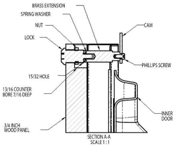
Figure 10
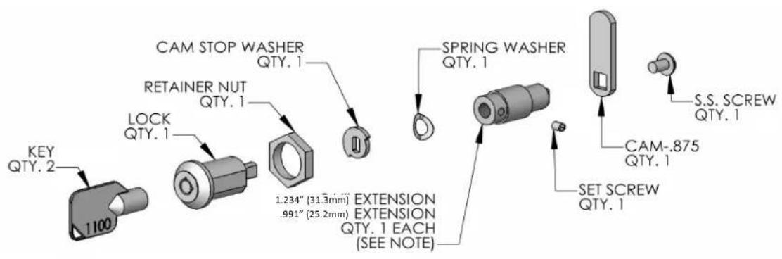
Figure 11
Step 9: Secure overlay panel to the door.
With the #10 wood screws provided, fasten the overlay panel to the door. (See Figure 12).
Step 10: Install lock cam (Models with locks only).
Attach the lock cam to the back of the lock assembly with the phillips head machine screw provided. Orient the lock cam vertically when installing on the lock.
Press the door gasket into the door channel. Make certain the gasket corners are fully inserted. If applicable insert the key into the lock and make certain the lock operates properly.
Step 12: Install the door
Install the top and bottom hinge adapter bushings back into the hinge adapters that were removed in step 6. Install the door by reversing the procedure from step 2. Install the top hinge pin so the screw head is flush with the top surface of the hinge If applicable insert key into lock and verify the lock cam works properly with the catch bracket on the front of the refrigerator cabinet.
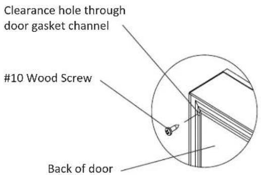
Figure 12
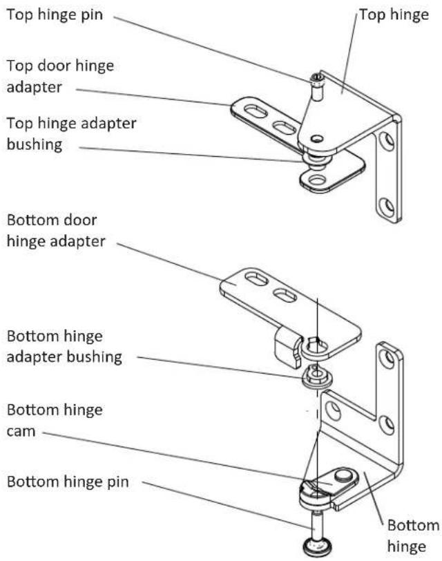
Figure 13 Right hand hinges shown
Insert Wine Bottles
The five (5) pull-out shelves each hold four (4) bottles. See Figure 14 for typical wine bottle spacing. Care should be taken when storing extra tall bottles in the wine cradle at the bottom of the compartment because they may prevent the door from closing.
Loading Tips and Suggestions
The bottles on the top rack directly under the light will be exposed to a slightly higher temperature when the light is on. Position your wines accordingly and REMEMBER TO TURN OFF THE LIGHT WHEN IT IS NO LONGER NEEDED.
Keep wines that you plan to use for everyday drinking and entertaining on the front half of the racks where labels are completely visible. Place wines for aging or longer term storing in the rear.
Pull-out Racks
The five (5) pull-out wine racks may be pulled out approximately seven (7) inches to facilitate adding or removing bottles. DO NOT lean on or press down heavily on the wine shelves. Doing so may damage the shelves and the wine bottles stored on them. Pull the wine racks out gently and carefully to minimize unsettling your wine collection. Avoid pulling out more than one rack at any time to maintain stability.
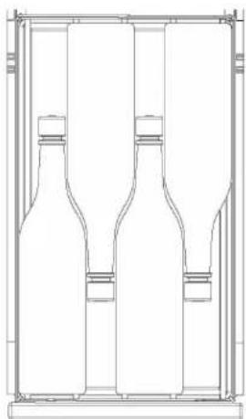
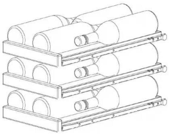
Single Bottle Racks
The single level roll out racks allow you to easily view and access your inventory without disturbing other bottles (see Figure 16).
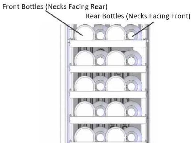
Figure 14
natural_image
3D rendering of stacked cylindrical components in a metal rack structure (no text or symbols visible)Figure 15
natural_image
Technical line drawing of a three-cylinder bottle assembly (no text or symbols)Figure 16
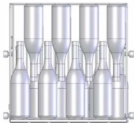
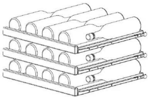
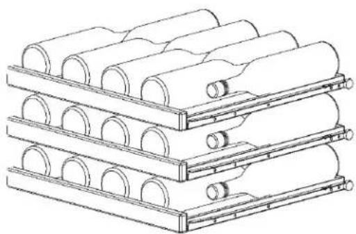
Insert Wine Bottles
The four (4) pull-out shelves each hold eight (8) bottles. See Figure 17 for typical wine bottle spacing. Care should be taken when storing extra tall bottles in the wine cradle at the bottom of the compartment because they may prevent the door from closing.
Loading Tips and Suggestions
Two (2) magnums can be placed in the bottle cradle as long as they are positioned horizontally.
The bottles on the top rack directly under the light will be exposed to a slightly higher temperature when the light is on. Position your wines accordingly and REMEMBER TO TURN OFF THE LIGHT WHEN IT IS NO LONGER NEEDED.
Keep wines that you plan to use for everyday drinking and entertaining on the front half of the racks where labels are completely visible. Place wines for aging or longer term storing in the rear.
Pull-out Racks
The four (4) pull-out wine racks may be pulled out approximately seven and a half (7.5) inches to facilitate adding or removing bottles. DO NOT lean on or press down heavily on the wine shelves. Doing so may damage the shelves and the wine bottles stored on them. Pull the wine racks out gently and carefully to minimize unsettling your wine collection. Avoid pulling out more than one rack at any time to maintain stability.
Single Bottle Racks
The single level roll out racks allow you to easily view and access your inventory without disturbing other bottles (see Figure 19).
Front Bottles (Necks Facing Rear)
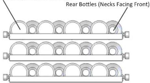
Figure 17
natural_image
3D technical illustration of stacked cylindrical components in a multi-tiered storage or assembly (no text or symbols visible)Figure 18
natural_image
3D technical illustration of five identical cylindrical mechanical components arranged in a row (no text or symbols visible)Figure 19
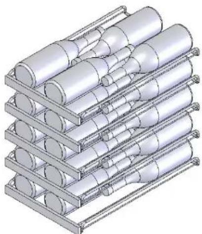
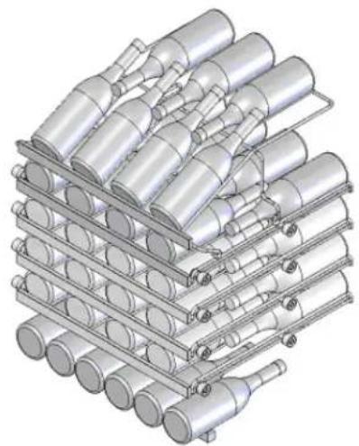
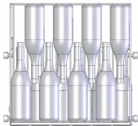
Insert Wine Bottles
The roll-out shelves each hold from 4 or 8 bottles per rack depending on model. See Figure 20 and 21 for typical wine bottle spacing. Care should be taken when storing extra tall bottles in the wine cradle at the bottom of the compartment because they may prevent the door from closing.
Loading Tips and Suggestions
Keep wines that you plan to use for everyday drinking and entertaining on the front half of the racks where labels are completely visible. Place wines for aging or longer term storing in the rear.
Roll-out Racks
The roll-out wine racks may be pulled out approximately 14 inches to facilitate adding or removing bottles. Do NOT lean on or press down heavily on the wine shelves. Doing so may damage the shelves and the wine bottles stored on them. Pull the wine racks out gently and carefully to minimize unsettling your wine collection. Avoid pulling out more than one rack at any time to maintain stability.
The single level roll-out racks allow you to easily view and access your inventory without disturbing other bottles.
natural_image
Stacked cylindrical mechanical components in a rack, no text or symbols visibleFigure 20 MPRO3WCM 4 bottles of wine per rack
natural_image
Stacked cylindrical storage racks with circular ends, no text or symbols visibleFigure 21 MPRO6WCM 8 bottles of wine per rack
The following suggestions will minimize the cost of operating your refrigeration appliance.
- Do not install your appliance next to a hot appliance, (cooker, dishwasher, etc.). heating air duct, or other heat sources.
- Install product out of direct sunlight.
- Assure the toe grille vents at front of unit beneath door is not obstructed and kept clean to allow ventilation for the refrigeration system to expel heat.
- Plug your appliance into a dedicated power circuit. (Not shared with other appliances).
- When initially loading your new product, or whenever large quantities of warm contents are placed within refrigerated storage compartment, minimize door openings for the next 12 hours to allow contents to pull down to compartment set-point temperature.
- Maintaining a relatively full storage compartment will require less appliance run time than an empty compartment.
- Assure door closing is not obstructed by contents stored in your appliance.
- Allow hot items to reach room temperature before placing in product.
- Minimize door openings and duration of door openings.
- Use the warmest temperature control set-point that meets your personal preference and provides the proper storage for your stored contents.
- For wine storage products:
When serving temperatures are not required, return the compartment(s) set-point to the ideal red and white wine long term storage temperature of 13^ C / 55^ F. - Minimize use of display lighting option on glass door products, (light stays on with door closed).
- When on vacation or away from home for extended periods, set the appliance to warmest acceptable temperature for the stored contents.
- Set the control to the "off" position if cleaning the unit requires the door to be open for an extended period of time.
Care and Cleaning
Front Grille
Periodically brush and vacuum the front grille area to maintain proper air flow through the condenser coil. See page 4, Figure 2.
Cabinet
The painted cabinet can be washed with mild soap and water and thoroughly rinsed with clear water. NEVER use abrasive scouring cleaners.
Interior
Wash interior compartment with mild soap and water. Do NOT use an abrasive cleaner, solvent, polish cleaner or undiluted detergent.
Pull-out Racks
The racks may be cleaned with mild soap and water and a soft cloth. Do NOT use any abrasive cleaners.
Glass Door
Use a glass cleaner or mild soap and water and soft cloth to clean the glass door model. Do NOT use any abrasive cleaners.
Door Gasket
The vinyl gasket may be cleaned with mild soap and water, a baking soda solution or a mild scouring powder.
Light Bulb Replacement

WARNING
DISCONNECT THE POWER CORD BEFORE ATTEMPTING LIGHT BULB REPLACEMENT. Failure to do so may result in an electrical shock that could severely injure you.
The 30WCM and 61WCM use one, 15 watt incandescent light bulb to illuminate the interior of the wine cellar. The light bulb is a very reliable electrical component, but should it not function properly, please call the dealer where you purchased your wine cellar from for a replacement light bulb. Use only an original equipment light bulb from your dealer or AGA MARVEL.

WARNING
Do NOT under any circumstance use a light bulb that exceeds 15 watts!
To replace the light bulb, disconnect power to the unit. Unscrew the old light bulb located behind the display housing at the top of the unit. Set the old light bulb aside. Screw the new light bulb into place. Reconnect power to the unit. Check to see if the light bulb operates properly to complete the installation.
The light bulb is not covered by your warranty. A replacement bulb can be obtained from your dealer or from AGA MARVEL.
The MPRO3WCM and MPRO6WCM models use an LED to illuminate the interior of the refrigerator. This component is very reliable, but should it fail, contact a qualified service technician for replacement of the LED.
In the Event of a Power Failure
If a power failure occurs, try to correct it as soon as possible. Minimize the number of door openings while the power is off so as not to adversely affect the unit's temperature.
Before You Call for Service
If the unit appears to be malfunctioning, read through this manual first. If the problem persists, check the troubleshooting guide below. Locate the problem in the guide and refer to the cause and its remedy before calling for service. The problem may be something very simple that can be solved without a service call. However, it may be required to contact your dealer or a qualified service technician.
If Service is Required:
- If the product is within the first year warranty period please contact your dealer or call AGA MARVEL Customer Service at 800.223.3900 for directions on how to obtain warranty coverage in your area.
- If the product is outside the first year warranty period, AGA MARVEL Customer Service can provide recommendations of service centers in your area. A listing of authorized service centers is also available at www.agamarvel.com under the service and support section.

WARNING
Electrocution Hazard - Never attempt to repair or perform maintenance on the unit until the main electrical power has been disconnected. Turning the unit control "OFF" does not remove electrical power from the units wiring.
- In all correspondence regarding service, be sure to give the service number, serial number, located on your product's serial plate, (see page 3) and proof of purchase.
- Try to have information or description of nature of the problem, how long the unit has been running, the room temperature, and any additional information that may be helpful in quickly solving the problem.
- Table D is provided for recording pertinent information regarding your product for future reference.
| For Your Records | |
| Date of Purchase | |
| Dealer's name | |
| Dealer's Address | |
| Dealer's City | |
| Dealer's State | |
| Dealer's Zip Code | |
| Appliance Serial Number | |
| Appliance Service Number | |
| Date Warranty Card Sent (Must be within 10 days of purchase). | |
Table D
| Problem Possible Cause Remedy | ||
| Unit not cold enough.Adjust temperatures (See “Set Temperatures” on page 6). | Control set too warm.Content temperature not stabilized.Excessive usage or prolonged door openings.Airflow to front grille blocked.Door gasket not sealing properly. | Adjust temperature colder. Allow 24 hours for temperature to stabilize.Allow temperature to stabilize for at least 24 hours, with minimal door openings.Airflow must not be obstructed to front grille. See “clearances” on page 4.Check door alignment and/or adjust or replace door gasket. |
| Unit too cold.Adjust temperatures (See “Set Temperatures” on page 6). | Control set too cold.Door gasket not sealing properly. | Adjust temperature warmer. (See page 6, “set temperature”). Allow 24 hours for temperature to stabilize.Check door alignment and/or adjust or replace door gasket. |
| No interior light. • Failed light bulb. • Replace light bulb, see page 21. | ||
| Light will not go out when door is closed. | Door not activating light switch. | Verify cabinet is level, refer to page 4 for leveling instructions.Verify the door is aligned properly, refer to page 15 for instructions. |
| Noise or Vibration. • Unit not level. • Level unit, see “Leveling Legs” on page 4. | ||
| Unit will not run. • Unit turned off. | Power cord not plugged in.No power at outlet. | Turn unit on. See “Start your Appliance” on page 6.Plug in power cord.Check house circuit. |
Entire Product
Limited One Year Parts and Labor Warranty
AGA MARVEL warrants that it will supply all necessary parts and labor to repair or replace in the end user's home or office, any component which proves to be defective in material or workmanship, subject to the condition and exclusions stated below, for a period of one year from the date of purchase by the end user.
Additional Second Through Fifth Year Limited Parts Only Warranty
During the four years following expiration of the one year limited warranty, AGA MARVEL will supply replacement parts for the hermetically sealed refrigeration system which consists of the compressor, condenser, drier, accumulator, bypass valve, connecting tubing and the evaporator that are proven to be defective due to workmanship or materials subject to the conditions and exclusions below.
The above warranties do not cover:
- Shipping costs of replacement parts or returned defective parts.
- Customer education or instructions on how to use the appliance.
- Any content loss due to product failure.
- Removal or installation of product.
Nor do the above warranties cover failure of this product or its components due to:
- Transportation or subsequent damages.
- Commercial use or use other than normal household or small office.
- Improper installation, misuse, abuse, accident or alteration, use of wiring not conforming to electrical codes, low or high voltages, failure to provide necessary maintenance, or other unreasonable use.
Parts or Service
Not Supplied or Designated by AGA MARVEL
The above warranties also do not apply if:
- The original bill of sale, deliver date, or serial number cannot be verified.
- Defective parts are not returned for inspection if so requested by AGA MARVEL.
- The refrigeration equipment is not in the possession of the original end use purchaser.
The warranties set forth herein are the only warranties extended by AGA MARVEL. Any implied warranties, including the implied warranty of merchantability, are limited to the duration of these express warranties. In no event shall AGA MARVEL be liable for any consequential or incidental damages or expenses resulting from breach of these or any other warranties, whether express or implied.
Some states do not allow the exclusion or limitation of consequential damages or a limitation on how long an implied warranty lasts, so the above exclusion or limitation may not apply to you. This warranty gives you specific legal rights and you may have other rights that may vary from state to state.
No person, firm, or corporation is authorized to make any other warranty or assume any other obligation for AGA MARVEL. These warranties apply only to products used in any of the fifty states of the United States and the District of Columbia.
To obtain performance of this warranty, report any defects to:
AGA MARVEL
1260 E. VanDeinse St.
Greenville MI 48838
Phone: 800.223.3900


www.agamarvel.com
AGA MARVEL
1260 E. VanDeinse St.
Greenville MI 48838
800.223.3900
41012684-EN Rev E 8/12/13
All specifications and product designs subject to change without notice. Such revisions do not entitle the buyer to corresponding changes, improvements, additions, replacements or compensation for previously purchased products.
natural_image
Illustration of a white electrical plug and two separate electrical socket (no text or symbols)Figure 4
natural_image
3D illustration of stacked cylindrical components in a rack structure (no text or symbols)Figure 15

natural_image
Technical line drawing of a three-cylinder bottle assembly (no text or symbols)Figure 16
natural_image
Three parallel cylindrical mechanical components with circular holes, shown from different angles (no text or symbols)Figure 17

natural_image
3D rendering of stacked cylindrical mechanical components (no text or symbols visible)Figure 18
natural_image
3D technical illustration of a multi-cylinder bottle assembly with no visible text or symbolsFigure 19
Supports coulissants
natural_image
Technical line drawing of stacked cylindrical components in a rack (no text or symbols)Figure 20 MPRO3WCM 4 bottles of wine per rack
natural_image
Stacked cylindrical storage racks with circular ends, no text or symbols visibleFigure 21 MPRO6WCM 8 bottles of wine per rack
- Installation Operation and Maintenance Instructions
- CONTENTS
- Important Safety Instructions
- Recognize Safety Symbols, Words, and Labels.
- WARNING
- CAUTION
- NOTE
- Remove Interior Packaging
- Important
- Note to Customer
- Warranty Registration
- Help Prevent Tragedies
- Select Location
- Cabinet Clearance
- Front Grille
- Leveling Legs
- Electrical Connection:
- Starting your refrigerator
- Turning your refrigerator ON or OFF
- Set temperature
- Refrigerator operation
- Alarms
- Alarm Mute
- Step 1: Verify door alignment
- Step 2: Remove door
- Step 3: Remove gasket
- Step 4: Cut overlay panel
- Step 5: Drill hinge clearance holes in overlay panel
- Step 6: Drill panel mounting holes
- Step 7: Mark and drill lock hole.
- Step 8: Assemble the lock parts
- Step 9: Secure overlay panel to the door.
- Step 10: Install lock cam (Models with locks only).
- Step 12: Install the door
- Insert Wine Bottles
- Loading Tips and Suggestions
- Pull-out Racks
- Single Bottle Racks
- Roll-out Racks
- The following suggestions will minimize the cost of operating your refrigeration appliance.
- Care and Cleaning
- Cabinet
- Interior
- Glass Door
- Door Gasket
- Light Bulb Replacement
- In the Event of a Power Failure
- Before You Call for Service
- If Service is Required:
- Entire Product
- Limited One Year Parts and Labor Warranty
- Additional Second Through Fifth Year Limited Parts Only Warranty
- Parts or Service
- Not Supplied or Designated by AGA MARVEL
- AGA MARVEL
- Supports coulissants
Brand : Marvel
Model : MPRO6WCM
Category : Wine cellar