
DPAC7008 - Air Conditioning DANBY - Free user manual and instructions
Find the device manual for free DPAC7008 DANBY in PDF.
Download the instructions for your Air Conditioning in PDF format for free! Find your manual DPAC7008 - DANBY and take your electronic device back in hand. On this page are published all the documents necessary for the use of your device. DPAC7008 by DANBY.
USER MANUAL DPAC7008 DANBY
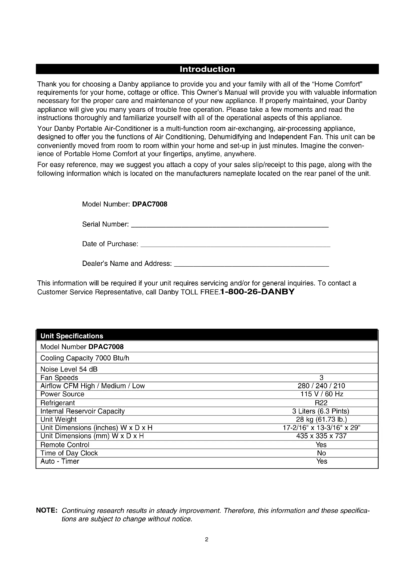
Power Cord Storage Removable Water Tank Air Filter CoverIntroduction Thank you for choosing a Danby appliance to provide you and your family with all of the “Home Comfort” requirements for your home, cottage or office. This Owner’s Manual will provide you with valuable information necessary for the proper care and maintenance of your new appliance. If properly maintained, your Danby appliance will give you many years of trouble free operation. Please take a few moments and read the instructions thoroughly and familiarize yourself with all of the operational aspects of this appliance. Your Danby Portable Air-Conditioner is a multi-function room air-exchanging, air-processing appliance, designed to offer you the functions of Air Conditioning, Dehumidifying and Independent Fan. This unit can be conveniently moved from room to room within your home and set-up in just minutes. Imagine the conven- ience of Portable Home Comfort at your fingertips, anytime, anywhere. For easy reference, may we suggest you attach a copy of your sales slip/receipt to this page, along with the following information which is located on the manufacturers nameplate located on the rear panel of the unit. Model Number: DPAC7008 Serial Number: ___________________________________________________ Date of Purchase: _________________________________________________ Dealer’s Name and Address: ________________________________________ This information will be required if your unit requires servicing and/or for general inquiries. To contact a Customer Service Representative, call Danby TOLL FREE.
NOTE: Continuing research results in steady improvement. Therefore, this information and these specifica- tions are subject to change without notice. Unit Specifications Model Number DPAC7008 Cooling Capacity 7000 Btu/h Noise Level 54 dB Fan Speeds 3 Airflow CFM High / Medium / Low 280 / 240 / 210 Power Source 115 V / 60 Hz Refrigerant R22 Internal Reservoir Capacity 3 Liters (6.3 Pints) Unit Weight 28 kg (61.73 lb.) Unit Dimensions (inches) W x D x H 17-2/16" x 13-3/16" x 29” Unit Dimensions (mm) W x D x H 435 x 335 x 737 Remote Control Ye s Time of Day Clock No Auto - Timer Ye sThe power cord supplied with this air conditioner contains a current leakage detection device designed to reduce the risk of fire. Please refer to the section "Power Supply Cord" for details. In the event the power supply cord is damaged, it cannot be repaired it must be replaced with a new cord from the Product Manufacturer.
- Under no circumstances should this device be used to turn the air conditioner on or off.
- The ‘RESET’ button must always be pushed in (engaged) for correct operation.
- The power supply cord must be replaced if it fails to reset when the ‘TEST’ button is pushed in.
- If the power supply cord is damaged, it cannot be repaired. It must be replaced with a new cord obtained from the Product Manufacturer. Important Safety Instructions Electrical Specifications
1. Check available power supply and resolve any
wiring problems BEFORE installation and opera- tion of this unit. All wiring must comply with local and national electrical codes and be installed by a qualified electrician. If you have any questions regarding the following instructions, contact a qualified electrician.
2. This appliance draws 6.5 nameplate amps under
Cooling Mode and may be used in any properly wired, general purpose 15 amp household grounded receptacle.
3. For your safety and protection, this unit is
grounded through the power cord plug when plugged into a matching wall outlet. If you are not sure whether the wall outlets in your home are properly grounded, please consult a qualified electrician.
4. DO NOT USE PLUG ADAPTERS OR REGULAR
EXTENSION CORDS WITH THIS UNIT. If it is necessary to use an extension cord with this unit, use an approved “air conditioner” extension cord only (available at most hardware stores). 5. To avoid the possibility of personal injury, alwaysdisconnect the power supply to the unit, beforeinstalling and/or servicing. Table 1 Suggested Individual Branch Circuit Nameplate Amps AWG Wire Size*
AWG- American Wire Gage* Based on copper wire at 60°C temperature rating. Table 2 Receptacle and Fuse Types Rated Volts 125 Amps 15 Wall Outlet Fuse Size 15 Time Delay Fuse Plug Type (or circuit breaker)
The power cord supplied with this air conditioner contains a device that senses damage to the power cord. To test if your power supply cord is working properly, you must do the following;
1. Connect the power supply cord to an electrical
2. The power supply cord is inclusive of two buttons
located on the head of the plug. One button is marked ‘TEST’, the other button is marked ‘RESET’. Press the ‘TEST’ button, you will hear a click as the ‘RESET’ button pops out.
3. Press the ‘RESET’ button, you will hear a click as
4. The power supply cord is now energized and
supplying electricity to the air conditioner. (On some products this is also indicated by a light on the plug head). CAUTION Do not leave this unit unattended in a space where people or animals who cannot react to a failed unit are located. A failed unit can cause extreme overheating or death in such an enclosed, unattended space.
Power Supply Cord WARNING!
Improper connection of the ground- ing plug can result in a risk of; Fire, Electric Shock and/or Injury to Persons associated with the Appliance. Check with a qualified electrician or service representative if you are in doubt that the appliance is properly grounded.Accessories Installation Accessories Fig. 1 Description Quantity Flexible exhaust hose, collar & adapter .....1/set
Adjustable window door slider kit .............1/set from 22 9/16" (67.5 cm) up to 48 7/16" (123 cm) Direct Drain Adapter (not shown) ..............1 pc.
- The garden hose for elongated direct drain appli- cations is not included with this unit. NOTE: The exhaust window kit must be installed at all times when the unit is operating under the AIR CONDITIONING mode.
CAUTION To avoid installation/operation difficulties, read these instructions thoroughly. Electric Shock Hazard To avoid the possibility of personal injury, disconnect power to the unit before installing or servicing. Energy-Saving Tips Your Danby appliance is designed to be highly efficient in energy savings. Follow these recom- mendations for greater efficiency:
1) Select a thermostat setting that suits your com-
fort needs and leave at that chosen setting.
2) The air filter is very efficient in removing airborne
particles. Keep the air filter clean at all times.
3) Use drapes, curtains or shades to keep direct
sunlight from penetrating and heating room, but do not allow drapes or curtains to obstruct the air flow around the unit.
4) Start your air conditioner before the outdoor air
becomes hot and uncomfortable. This avoids an initial period of discomfort while the unit is cool- ing off the room. Use of the automatic start/stop programmable TIMER feature can be a major asset in this regard if utilized to the fullest extent.
5) When outdoor temperatures are cool enough,
turn the air conditioner off and use the FAN MODE on HIGH, MEDIUM or LOW. This circu- lates indoor air, providing some cooling comfort and utilizes less electricity. Window Exhaust Adapter Adjustable Window Slider Kit 22 9/16" (67.5 cm)~ 48 7/16" (123 cm) Flexible Exhaust Hose Fig. 1 Installation Accessories Adapter IMPORTANT There should be at least 11.8" (30 cm) clearance between the unit and any other objects or building structure and should be installed on a level sur- face. The unit does not have to be vented outside during Dehumidifer or Fan Only mode operation. Hose CollarDirect Drain Instructions
1. Remove the internal water tank; gently lift then
pull outward as shown in Figure 2.
2. Locate the direct drain hose Figure 3 (a), and
proceed to remove the black plug located at the end of the hose Figure 3 (b).
3. Route the end of the hose under the side of the
water tank, then through the hole provided on the face of the tank and place the water tank back into the cabinet (As shown in Figure 4).
required , attach the included drain hose adapter (Fig 4) to the end of the drain tube and attach a section of garden hose (not included) to suit your continuous drain option requirements. Important: Ensure that the drain hose section does not interfere with the correct positioning of the water tank inside the cabinet. Please Note: Remember to reverse the above direct drain instructions when relocating the unit to a location where continuous drain is not possible. Failure to replace and recap the direct drain hose may resulting in flooding of the immediate area.
Fig.2 Fig.4 Water Tank Safety Feature This unit is equipped with a fail-safe switch mecha- nism which prevents the unit from condensing water in the event the internal water tank is accidentally displaced and/or is full. If this situation occurs, the (RED) WATER FULL indicator light will illuminate. This condition will remain steady until the external water tank is emptied. NOTE: No cooling will occur until the internal tank is emptied and/or re-positioned. It may take several minutes before the compressor resumes normal operation. CAUTION During air conditioning and dehumidifier mode, if the compressor cycle is interrupted (water full condition, unplugged, power failure,etc.) and reinstated imme- diately thereafter, (within 3-5 minutes) a “compressor protection circuit” is automatically activated. The compressor cannot operate during “compressor pro- tection” mode. (this is normal) It may take 3-5 min- utes before the “protection circuit” self-deactivates. DO NOT ATTEMPT TO START THE UNIT (COM- PRESSOR) DURING THIS PERIOD.
CAUTION Always empty the external water tank before attempting to move or re-locate the unit to another location. Direct Drain Adapter Direct Drain TubeCF MODE
Cool Mode: Illuminates while the unit is operating in air conditioning mode. Fan Only Mode: Illuminates while unit is operating in ‘Fan Only’ mode. Dehumidifier (Dry) Mode: Illuminates while the unit is operating in dehumidi- fication mode.
timer setting has been initiated. Water Full: Illuminates to indicate that the inter water tank is full and will have to be emptied. TEMPERATURE DISPLAY: Displays current ambient room (fan mode only) or set temperature in Celsius or Fahrenheit scale.
Fahrenheit: Signifies the temperature is currently displayed in Fahrenheit. AUTO-OFF: Signifies the auto- off timer setting has been initiated. POWER SWITCH: Turns unit On / MODE : Allows you to scroll through and select the desired operating mode. FAN : Select from three different fan settings; High Medium and Low. AUTO-TIMER Adjust : TIMER-ON: Used to initiate the AUTO- ON (start) timer and adjust Timer On settings forward (0.5 hour increments). TIMER-OFF: Used to initiate the AUTO-OFF (stop) timer and adjust Timer Off settings forward (0.5 hour TEMPERATURE Adjust: Continually depress to adjust tempera- ture settings forward (1°C / °F incre- ments). Continually depress to adjust tempera- ture settings backward (1°C / °F incre- ments). Note : This appliance allows you to select the tem- perature scale to be displayed in either the “Celsius” or Fahrenheit” according to your preference. To change temperature scale displayed on the con- trol panel display, press and hold and arrow buttons simultaneously to alternate between the “Celsius” & “Fahrenheit” scale. 7Air Conditioning Operating Instructions: IMPORTANT: The exhaust hose must be properly vented (outdoors) during air conditioning mode.
switch on the unit, and the previous set tempera- ture will be shown in the temperature display area of the control panel.
2) Press the MODE key
Fig B. until the COOL indi- cator light illuminates on the control panel Fig C. Each depression of the MODE key will advance to a different mode setting (Cool - Dehumidifier - Fan ).
3) Press the appropriate increase or decrease
buttons Fig D to select a suitable operating temperature setting. Temperature settings are adjustable between 17°C (62.6°F) ~ 30°C (86°F ).
4) Press the FAN key
Fig E to select the desired fan speed setting (High -Med -Low ). Your selection will appear on the control panel (each depression of the fan key will advance to a different setting).
- Cooling stops automatically when the set temperature is achieved. Cooling resumes when the room temperature rises above the “set” temperature level.
MODE MODE MODE High Medium Low Fig FFig BFig AFig DFig E MODE Fig C orFan Operating Instructions: Note: During Fan mode, the exhaust hose does not have to be vented outdoors.1) Press the (on/off) key pad to switch on theunit. Fig G
2) Press the MODE key
Fig H until the FAN indica-tor illuminates on the control panel Fig I . Eachdepression of the MODE key will advance to adifferent mode setting (Cool -Dehumidifier- Fan ).
3) Press the FAN key Fig J to select the desired
FAN SPEED setting. Your selection will appearon the control panel. Each depression of the fankey will advance to a different fan speed (High-Med -Low ) as shown in Fig K.
High Medium Low MODE
MODE Fig M Dehumidifier Operating Instructions: Note: During dehumidifier mode, the exhaust hose does not have to be vented outdoors.1) Press the (on/off) key pad to switch on theunit. Fig G
2) Press the MODE key
Fig L until the DRY indica-tor illuminates on the control panel Fig M . Eachdepression of the MODE key will advance to adifferent mode setting (Cool -Dehumidifier- Fan ).
Important : There is no fan speed or temperatureadjustment during dehumidifier mode. The fanspeed is factory set for ‘High’ and the dehumidifieroperates continuously (non-stop) regardless ofambient humidity level or set temperature.Fig JFig KFig L
MODE 9Auto-Timer Instructions: The AUTO-TIMER feature offers a unique selection of multiple choice, fully automatic on and/or off (start/stop) programs between 0.5 - 24 hrs under any one mode of your Home Comfort unit. The programs are as follows: a) Auto -Off: Pre-select a time that will turn off the unit automatically (between 0.5 - 24 hrs.). b) Auto-On: Pre-select a time that will turn on the unit automatically (between 0.5 - 24 hrs.). c) Auto-On & Auto-Off:Pre-select a time that will turn the unit ON / OFF (automatically) at speci- fied times (between 0.5 - 24 hrs). Note: These functions must be performed daily, as the program is automatically canceled/erased after the program has ended . Setting the AUTO-OFF TIMER Before setting the AUTO-OFF timer, the unit must be (operational) turned on.
1) Press the TIMER-OFF key pad (
Fig N) to ini- tiate the AUTO-OFF time sequence. The “AUTO- OFF” indicator ( Fig O) will illuminate on the con- trol panel and the timer digits ( Fig P) will appear.
o adjust Timer-Off settings forward by 0.5 hour increments (between
3) The timer setting will remain in the display win-
dow for three seconds before automatically reverting back to the temperature display.
4) To view the timer setting at any time; press the
TIMER-OFF key pad again and the timer length you selected will be shown in the display window.
DSetting the AUTO-ON TIMER You must select all appropriate settings required to operate under the AUTO TIMED program before ini- tiating the AUTO-ON program;
- Select the appropriate MODE under which you want the unit to operate (Cool, Dehumidify or Fan).
- Select the appropriate FAN SPEED set- ting, under which you want the unit to operate; Hi, Medium or Low. (excluding Dehumidifying, as this mode has one (1) pre-set fan speed setting only).
- To set the AUTO-ON timer, the unit must be turned “off” (non-operational).
1) Press the (on/off) key pad to switch on the
2) Select all appropriate operational settings (see
3) Press the (on/off) key pad to switch the unit
Fig T) to initi- ate the AUTO-ON time sequence. The “AUTO- ON” indicator light ( Fig U) will illuminate on the control panel and the timer digits ( Fig V) will appear in the display window.
o adjust Timer On settings forward by 0.5 hour increments (0.5 ~ 24 hours).
6) To view the timer setting at any time; press the
TIMER-OFF key pad again and the timer length you selected will be shown in the display window.
- The unit will start automatically at the specified AUTO-ON set time.
- To cancel or override the AUTO-ON program, simply turn on the unit anytime prior to when the AUTO-ON time is scheduled to operate. Setting the AUTO-ON & OFF timer Follow the above steps to set the auto-on timer then proceed to set the auto-off timer (see page 11). When setting the auto-on and auto off timer, the operation (running) time of the unit is the difference between the auto-on and auto-off set timer lengths. For example,to have the unit automatically power on two hours from now, then operate for one hour and power off; Set the auto-on timer length to 2 hours, and set the auto-off timer length to 3 hours, this sets the timer program for 1 hour of operation.
4) Used to increase or decrease the temperature to
select a suitable operating temperature setting.
5) Lock: Prevents the remote control settings from
being inadvertently being changed.
timer and adjust Timer On settings forward (0.5/1h)
8) TIMER-OFF: Used to initiate the AUTO-OFF
(stop) timer and adjust Timer Off settings forward (0.5/1h) To operate the hand held remote control will require two “AAA” Alkaline batteries (included). Batteries should be replaced when: a) No signal (beep) is heard when attempting to program the main unit. b) The main unit does not respond to a command issued by the remote. Battery replacement:
1. Slide the rear cover on the remote in the general
direction of the arrow. Continue pulling (gently) until the cover seperates completely from the unit.
2. Insert (2) batteries (AAA) following the same ori-
entation (polarity) depicted inside the battery cham- ber (+/-).
3. Re-install rear cover.
4. If the remote control will not be used for extend-
ed periods of time (vacations, etc.), batteries should be removed. The remote operates within a range of 8 meters (26 ft.) from the receiver located inside the main unit. Any obstruction between the receiver and remote may cause signal interference, limiting the ability to program the main unit. Note:
Electronic Display12 Care and Maintenance
1) Do Not use gasoline, benzene, thinner or any
other chemicals to clean this unit ,as these sub- stances may cause damage to the finish and deformation of plastic parts.
2) Never attempt to clean the unit by pouring water
directly over any of the surface areas, as this will cause deterioration of electrical components and wiring insulation. Storage and End of Season Care If the unit will not be in use for a long period oftime or is to be stored.
1. Remove the water tank and place a trip tray
beneath sump drain tube Fig 7 (c).
2. Remove the black plug Fig 7 (d) to manually
release the water from the internal reservoir. CAUTION: Failure to replace and recap the direct sump drain tube prior to using the unit may resulting in flooding of the immediate area. Removal and Cleaning of the Air Filter If the air filter becomes clogged with dust/dirt, air flow is restricted and reduces cooling efficiency. The air filter should be cleaned every two (2) weeks. More frequent cleaning may be necessary depend- ing upon indoor air quality. NOTE: The air filter is located at the (upper) rear side of the unit.
1) To remove the air filter: Pull the air filter cover
upward in the direction of the arrow Fig 8 and remove the air filter.
2) Dust/Dirt clogged in the filter can be removed by
vacuum cleaning the soiled areas.
4) The filter can also be washed in lukewarm soapy
water while rubbing it lightly with a brush. A mild detergent (dishwashing soap) is recommended.
5) Rinse the filter well using clean water. Allow
time to dry before reinstalling into the unit.
6) Replace the air filter and cover.
7) Replacement air filter information is available
by the Customer Service Department at: 1-800-26-DANBY (1-800-263-2629) CAUTION Never operate the unit without the air filter in place as this may result in damage to the unit. CAUTION Before cleaning or servicing this unit, it is recom- mended that the unit be disconnected from any electrical supply outlet.
Fig.7LIMITED AIR CONDITIONER WARRANTY This quality product is warranted to be free from manufacturer’s defects in material and workmanship, provided that the unit is used under the normal operating conditions intended by the manufacturer. This warranty is available only to the person to whom the unit was originally sold by Danby or by an authorized distributor of Danby, and is non-transferable.
Plastic parts, are warranted for thirty (30) days only from purchase date, with no extensions provided. First 12 Months During the first twelve (12) months, any electrical parts of this product found to be defective, including any sealed system units, will be repaired or replaced, at warrantor’s option, at no charge to the ORIGINAL purchaser. To obtain Danby reserves the right to limit the boundaries of “In Home Service” to the proximity of an Authorized Service Depot. Any appliance Service requiring service outside the limited boundaries of “In Home Service” , it will be the consumer’s responsibility to transport the appliance (at their own expense) to the original retailer (point of purchase) or a service depot for repair. Contact your dealer from whom your unit was purchased, or contact your nearest authorized Danby service depot, where service must be performed by a qualified service technician. If service is performed on the units by anyone other than an authorized service depot, or the unit is used for commercial application, all obligations of Danby under this warranty shall be at an end. EXCLUSIONS Save as herein provided, Danby Products Limited (Canada) or Danby Products Inc. (U.S.A.), there are no other warranties, conditions, representations or guaran- tees, express or implied, made or intended by Danby Products Limited or its authorized distributors and all other warranties, conditions, representations or guar- antees, including any warranties, conditions, representations or guarantees under any Sale of Goods Act or like legislation or statue is hereby expressly exclud- ed. Save as herein provided, Danby Products Limited (Canada) or Danby Products Inc. (U.S.A), shall not be responsible for any damages to persons or property, including the unit itself, howsoever caused or any consequential damages arising from the malfunction of the unit and by the purchase of the unit, the purchaser does hereby agree to indemnify and save harmless Danby Products Limited from any claim for damages to persons or property caused by the unit. GENERAL PROVISIONS No warranty or insurance herein contained or set out shall apply when damage or repair is caused by any of the following:
2) Damage in transit or when moving the appliance.
3) Improper power supply such as low voltage, defective house wiring or inadequate fuses.
4) Accident, alteration, abuse or misuse of the appliance such as inadequate air circulation in the room or abnormal operating conditions, (extremely high or low room temperature).