DG4300 - Generator DEWALT - Free user manual and instructions
Find the device manual for free DG4300 DEWALT in PDF.

| Product Type | Portable Generator |
| Brand | DEWALT |
| Model | DG4300 |
| Alternator | Brushless, Bipolar |
| Max AC Output | 4300 W |
| Rated AC Output | 3800 W |
| Rated Voltage | 120/240 V (selectable) |
| Rated Current (120/240 V) | 31.7 / 15.9 A |
| Frequency | 60 Hz |
| Phase | Single Phase |
| Engine | Honda GX240, 8 HP |
| Fuel Tank Capacity | 5 gal (18.9 L) |
| Recommended Fuel | Unleaded gasoline (86 octane or higher) |
| Oil Capacity | 1.16 US pt (1.10 L) |
| Recommended Oil | SAE 10W-30 API SF or SG |
| Low Oil Shutdown | Yes |
| Starting System | Recoil (Rope Start) |
| Outlets | 2 x GFCI 120 V 20 A, 1 x Locking 120 V 30 A, 1 x Locking 120/240 V 20 A |
| Idle Control | Yes |
| Dimensions (L x W x H) | 24.4 x 21.7 x 20.1 in (62 x 55.1 x 51.1 cm) |
| Dry Weight | 159 lb (72.1 kg) |
| Warranty | 2 years |
| Electrical Protection | Main circuit breaker, thermal circuit breakers, GFCI |
| Grounding | Required (grounding bolt) |
Frequently Asked Questions - DG4300 DEWALT
User questions about DG4300 DEWALT
0 question about this device. Answer the ones you know or ask your own.
Ask a new question about this device
Download the instructions for your Generator in PDF format for free! Find your manual DG4300 - DEWALT and take your electronic device back in hand. On this page are published all the documents necessary for the use of your device. DG4300 by DEWALT.
USER MANUAL DG4300 DEWALT
DEWALT Industrial Tool Co., 701 East Joppa Road, Baltimore, MD 21286 Printed in Japan (JUL02) Form No. 612541-00 DG2900 etc.
Copyright © 2002
The following are trademarks for one or more D≡WALT power tools: the yellow and black color scheme; the "D" shaped air intake grill; the array of pyramids on the handgrip; the kit box configuration; and the array of lozenge-shaped humps on the surface of the tool.
Before returning this product call
1-800-4-DEWALT
IF YOU SHOULD EXPERIENCE A PROBLEM WITH YOUR DEWALT PURCHASE, CALL 1-800-4 DEWALT.
IN MOST CASES, A DEWALT REPRESENTATIVE CAN RESOLVE YOUR PROBLEM OVER THE PHONE.
IF YOU HAVE A SUGGESTION OR COMMENT, GIVE US A CALL.
YOUR FEEDBACK IS VITAL TO THE SUCCESS OF DEWALT'S QUALITY IMPROVEMENT PROGRAM.
Questions? See us on the World Wide Web at www.dewalt.com
INSTRUCTION MANUAL
GUIDE D'UTILISATION
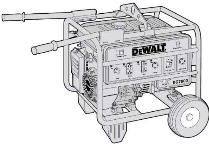
Generator with Electric Start DG6000E, DG7000E
natural_image
Line drawing of a DeWALT gas generator with wheels and control panel (no text or symbols on the device itself)HONDA 13 HP, OHV GX ENGINE
IDLE CONTROL, LOW OIL SHUT OFF
SUPER QUIET MUFFLER
HIGH AMP SURGE CAPACITY IDEAL FOR STARTING COMPRESSORS
MAINTENANCE FREE
BRUSHLESS ALTERNATOR
JOBSITE TESTED FRAME
WITH PANEL PROTECTION BARS
120V / 240V - 20/ 30 AMP RECEPTACLES
120V -20 AMP GFCI RECEPTACLES
1 YEAR FREE SERVICE CONTRACT
2 YEAR WARRANTY
DG7000 GENERATOR SHOWN
Product Specifications
Model DG2900 DG4300
Alternator
| Type Brushless, 2-Pole Brushless, 2-Pole | ||
| Excitation | Condenser | Condenser |
| Max AC Output 2900 4300 | ||
| Rated AC Output 2400 3800 | ||
| Rated Current (120/240 volt) | 20 Amp | 31.7/15.9 Amp |
| Phase | Single | Single |
| Frequency | 60 Hz | 60 Hz |
| Engine | ||
| Model | GX160 | GX240 |
| Horse Power | 5.5 | 8 |
| Fuel Tank Capacity | 3 Gal | 5 Gal |
| Recommended Fuel | Unleaded Gasoline(86 Octane or Higher) | Unleaded Gasoline(86 Octane or Higher) |
| Oil Capacity 0.63 US qt. | 1.16 US qt. | |
| Recommended Oil | SAE 10W-30 API SF or SG | SAE 10W-30 API SF or SG |
| Low Oil Shutdown | Yes | Yes |
| Starting system | Recoil | Recoil |
| Receptacles | ||
| 120 Volt 20 Amp GFCI Duplex | Yes (1) | Yes (2) |
| 120 Volt 20 Amp Twist-Locking (GFCI protected) | Yes (1) | No |
| 120 Volt 30 Amp Twist-Locking | No Yes (1) | |
| 120/240 Volt 20 Amp Twist-Locking | No Yes (1) | |
| 120/240 Volt 30 Amp Twist-Locking | No | No |
| General | ||
| Dimensions* (in.)(LxWxH) | (22.4x19.1x18.9) | (24.4x21.7x20.1) |
| Dry Weight* | 99 lb (44.9 kg) | 159 lb (72.1 kg) |
| Model | DG6000/DG6000E | DG7000/DG7000E |
| Alternator | ||
| Type Brushless, 2-Pole Brushless, 2-Pole Excitation Condenser | Condenser | |
| Max AC Output 6000 7000 Rated AC Output 5000 6000 | ||
| Rated Current (120/240 volt) | 41.7/20.8 Amp | 50/25 Amp |
| Phase | Single | Single |
| Frequency | 60 Hz | 60 Hz |
| Engine | ||
| Model | GX340 | GX390 |
| Horse Power | 11 | 13 |
| Fuel Tank Capacity | 5 Gal | 5 Gal |
| Recommended Fuel | Unleaded Gasoline(86 Octane or Higher) | Unleaded Gasoline(86 Octane or Higher) |
| Oil Capacity 1.16 US qt. | 1.16 US qt. | |
| Recommended Oil | SAE 10W-30 API SF or SG | SAE 10W-30 API SF or SG |
| Low Oil Shutdown | Yes | Yes |
| Starting system | Recoil/Elec. Start | Recoil/Elec. Start |
| Receptacles | ||
| 120 Volt 20 Amp GFCI Duplex | Yes (2) | Yes (2) |
| 120 Volt 20 Amp Twist-Locking (GFCI protected) | No | No |
| 120 Volt 30 Amp Twist-Locking | Yes (2) | Yes (2) |
| 120/240 Volt 20 Amp Twist-Locking | No | No |
| 120/240 Volt 30 Amp Twist-Locking | Yes (1) | Yes (1) |
| General | ||
| Dimensions* (in.)(LxWxH) | (26x21.7X20.5) | (26x21.7X20.5) |
| Dry Weight* | 185 lb (83.9 kg) | 200 lb (90.7 kg) |
* Dimensions and dry weight do not include wheel kit or battery compartment.
SAFETY INSTRUCTIONS FOR GENERATORS
SAVE THESE INSTRUCTIONS FOR FUTURE USE
⚠ WARNING! Read and understand all instructions. Familiarity and proper training are required for the safe operation of generators. A generator operated improperly or by untrained personnel can be dangerous. Become familiar with all of the generator's controls, output receptacles and connections. Know how to stop generator in case of emergency. Failure to follow all instructions listed below may result in electrical shock, property damage, and/or serious personal injury or death. This manual contains IMPORTANT SAFETY INSTRUCTIONS for models DG2900, DG4300, DG6000, DG7000, DG60000E and DG7000E. It is important to SAVE THESE INSTRUCTIONS.
Do not operate the generator unless it is fully assembled.
NOTE: All D EWALT generators come with a Honda engine owner's manual. The Honda manual overrides this manual on all engine topics. Honda engine manuals are available through DEWALT at 1-800-4-DEWALT.
⚠ WARNING! CARBON MONOXIDE HAZARDS
Exhaust contains poisonous carbon monoxide, a colorless and odorless gas. Breathing exhaust can cause loss of consciousness and may lead to death. If you run the generator in an area that is confined, or even partially enclosed, the air you breathe could contain a dangerous amount of exhaust gas. To keep exhaust from building up, provide adequate ventilation. Do not operate the generator in a room, cave, or tunnel unless professionally installed exhaust hoses are used.
⚠ WARNING! ELECTRIC SHOCK HAZARDS
The generator produces enough electrical power to cause serious shock or electrocution if misused. Using a generator or an electrical device in wet conditions — near water, on wet grass, in damp areas, in rain or snow — could result in electrocution. Keep the generator dry at all times. This generator is not designed to be stored outdoors unprotected from the weather. Moisture or ice can cause a malfunction or short in electrical components, which could result in electrocution. Test GFCI outlets and accessories before each use. Check all electrical components on the control panel before each use.
Do not connect this generator to any building's electrical system unless a licensed electrician has installed an isolation switch. Failure to do so can result in property damage or death.
⚠ WARNING! FIRE & BURN HAZARDS
The exhaust system gets hot enough to ignite some materials. Keep generator at least 1 meter (3 feet) away from buildings and other equipment during or immediately after operation. Never enclose generator in any structure. Keep all flammable materials away from the generator.
The muffler becomes very hot during operation and remains hot for some time after the engine stops. Do not touch the muffler while the engine is running or hot. Allow the engine and the muffler to cool before storing. See storing instructions on page 2 of this manual.
Gasoline is highly flammable and poisonous. Always stop the engine and allow the muffler to cool before refueling. Never refuel while smoking or in the vicinity of an open flame or sparks. Never smoke near the generator. Always check for spilled fuel or fuel leaks. Make sure that any spilled fuel has been wiped up before starting the generator.
When operating or transporting the generator, be sure that it is kept upright. If the unit tilts, fuel may leak from the carburetor or fuel tank.
GROUNDING THE GENERATOR
Grounding the generator helps prevent electric shock from a ground fault condition. To ground the generator you will need a ground wire and grounding stake. These are not supplied with the generator. The ground wire should be a #8, stranded-copper wire. The grounding point should be copper or brass.
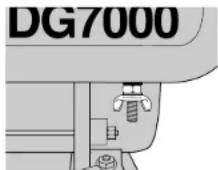
FIGURE 1: GROUNDING PLUG
-
Locate the ground plug below the generator control panel (shown in figure 1).
-
Attach a ground wire to the ground plug.
-
Drive the grounding point into the ground.
-
Attach the ground wire to the grounding point.
The generator should be grounded to a good ground source in compliance with National Electric Codes standards and local regulations. In some areas, generators are required to be registered with local utility companies.
⚠ WARNING! Use only grounded extension cords. Use only three wire or double-insulated power tools.
⚠ WARNING! Do not use metal pipe that is being used to carry combustible materials or gasses for the grounding point.
GROUND FAULT CIRCUIT INTERRUPT (GFCI)
On DeWALT generator models (DG2900, DG4300, DG6000, DG7000, DG6000E, and DG7000E), all 20 Amp receptacles are protected by a ground fault circuit interrupt (GFCI). On the DG2900, both receptacles are linked to the GFCI duplex. The GFCI shuts off the power to the receptacle when it senses small imbalances caused by current leakage to the ground.
⚠️ CAUTION: Each GFCI should be tested for proper operation every time the generator is used.
TO TEST A GFCI:
Start the generator. Turn the auto idle switch (figure 13H) off. (See page 4 for control panel layout information.) Push in the TEST button (A) on the receptacle. The RESET button (B) will pop out. Power is now off at the receptacle. If the RESET button does not pop out, the GFCI is not working. Do
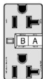
FIGURE 2
GFCI
RECEPTACLE
not run generator until the problem can be corrected. To restore power to receptacle, push the RESET button in. If the RESET button pops out during operation, stop the generator and check the generator and equipment for defects.
USE OF EXTENSION CORDS
Only use grounded extension cords that are rated for outdoor use and equipment with a third-wire ground. If using a twist-locking receptacle, you must connect through a GFCI Protected spider box or use an in-line GFCI adapter.
When a long extension cord is used to connect an appliance or tool to the generator, a voltage drop occurs. The longer the cord, the greater the voltage drop. This results in less voltage being supplied to the appliance or tool and increases the amount of current (amp) draw or reduces performance. A heavier cord with a larger wire size will reduce the voltage drop. Be sure to choose a cord that will supply enough voltage to operate your tool or appliance. The tables below indicate appropriate gauge for extension cords and the voltage drop caused by the use of extension cords, given different electrical loads.
⚠️ CAUTION: Operating equipment at low voltage can cause it to overheat. Using an excessively long extension cord can cause the cord to overheat.
⚠ WARNING: Keep electrical cords in good condition. Do not use worn, bare, or frayed cords because they can cause electrical shock.
Minimum Guage for Extension Cord Sets
| Volts Total Length of Cord in Feet | ||||
| 120V | 0–25 | 26–50 | 51–100 | 101–150 |
| 240V | 0–50 | 51–100 | 101–200 | 201–300 |
| Ampere Rating AWG | ||||
| 0–10 (A) | 16 | 16 | 14 | 14 |
| 10–13 (A) | 16 | 16 | 14 | 12 |
| 13–16 (A) | 14 | 14 | 12 | 12 |
| 16–25 (A) | 12 | 12 | 12 | 10 |
| 25–30 (A) | 10 | 10 | 10 | Not Recommended |
Extension
| Cord | Amp | Voltage | Drop |
| Length Load 16 AWG 14 AWG 12 AWG 10 AWG | |||
| 10A 2.0 | 1.3 | 0.8 0.5 | |
| 25 15A 3.0 | 1.9 | 1.2 0.8 | |
| Foot 20A 4.0 | 2.5 | 1.6 1.1 | |
| 30A 6.0 | 3.8 2.3 1.6 | ||
| 10A 4.0 | 2.5 | 1.6 1.1 | |
| 50 15A 6.0 | 3.8 | 2.3 1.6 | |
| Foot 20A 8.0 | 5.0 | 3.1 2.1 | |
| 30A 12.0 | 7.5 4.7 3.2 | ||
| 10A 8.0 | 5.0 | 3.1 2.1 | |
| 100 15A 12.0 | 7.5 | 4.7 3.2 | |
| Foot 20A 16.0 | 10.0 | 6.2 4.2 | |
| 30A 24.0 | 15.0 9.3 6.3 | ||
| 10A 12.0 | 7.5 | 4.7 3.2 | |
| 150 15A 18.0 | 11.3 | 7.0 4.7 | |
| Foot 20A 24.0 | 15.0 | 9.3 6.3 | |
| 30A 36.0 | 22.5 14.0 9.5 | ||
FAMILIARIZATION
Transporting
⚠️ CAUTION: Units are heavy. Observe safe lifting procedures when transporting.
Before transporting generator, it is important to turn off both the engine switch and the fuel petcock. Keep generator level at all times to prevent fuel spillage. Fuel vapor or spilled fuel may ignite.
⚠ WARNING: Contact with a hot engine or exhaust system can cause serious burns or fire. Let the engine and muffler cool before transporting the generator.
Storage
Make sure that the generator storage area is free of excessive humidity and dust. Store the generator in dry, well-ventilated area.
⚠ WARNING: Contact with a hot engine or exhaust system can cause serious burns or fires. Let the engine and muffler cool before storing the generator.
Accessories
Accessories available for generators include wheels, handles, a lifting hook, and frame. The battery frame is required for use with electric start generators (D6000E and D7000E).
Assembly of Accessories
NOTE: Two people are needed for these installations. Install the wheel kit before adding gasoline or engine oil to prevent damage to the engine. If you are installing accessories after running the generator, be sure that the gas tank is empty, and that the fuel petcock is turned to the off position, that is, horizontal to the ground. Be sure that the oil is drained from the engine. you may use figures 3 and 4 to check that the accessory kit contains the appropriate pieces.
NOTE: After approximately 20 hours of operation, accessory bolts may loosen. Tighten them as needed.
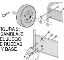
WHEEL KIT ASSEMBLY
(FIGURE 5)
Carefully tilt the generator so that it rests on the engine side. Install the two stands at the lower
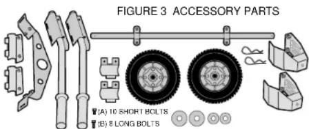
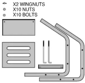
FIGURE 4: BATTERY FRAME PARTS, ELECTRIC START ONLY
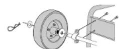
FIGURE 5
WHEEL KIT
AND
FOOT
ASSEMBLY
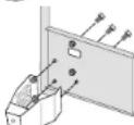
FIGURE 6: HANDLE AND LIFT HOOK ASSEMBLY
natural_image
Mechanical assembly diagrams showing two configurations with arrows indicating force or movement (no text or symbols present)chassis. Install the wheel axle to the upper chassis. Use the short bolts (figure 3A) for these two steps. Insert the two larger washers, on on each end of the axle. Slide the tires on the axle. Insert the two small washers on the outside of the wheels. Insert cotter pins into the holes in the axle. Place the generator upright so that it is resting on the wheels and stands.
HANDLE KIT ASSEMBLY (FIGURE 6)
Install handles on the engine side of the generator by placing the handle assembly on the top horizontal bars, and then inserting the bottom clamp. Use the long bolts (figure 3B) to secure the bottom clamp to the top clamp. Tighten the bolts until the assembly is snug or until the gap between the top and bottom clamps is closed.
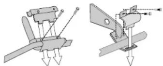
LIFTING HOOK ASSEMBLY (FIGURE 6)
Insert the lifting hook under the two horizontal bars, and position it according to the complete generator diagram at the beginning of this manual. Place the top clamp over the horizontal bars and fasten to the lifting hook using the long bolts (figure 3B). Tighten the bolts firmly until the gap between the top clamp and the lifting hook is closed. For correct location of lifting hook for the DG4300, DG6000 and DG7000, DG6000E and DG700E, please refer to the separate insert.
ELECTRIC START BATTERY FRAME ASSEMBLY
⚠ WARNING: Read and follow all safety instructions included with the battery.
You must use a 12V, 18-35 AH or more battery. It should measure no more than 8" long X 5-1/4" wide X 7" tall.
Attach the battery tray and guard to frame rods as shown in figure 7. Place the battery on the battery tray so that the bracket will not interfere with battery terminals as shown in figure 8. Insert the bent rods into holes in the battery tray. Align the battery bracket with threaded ends of rods. Be sure that the bracket will not contact the terminals of the battery. If the battery bracket contacts the battery terminals, it could cause a short. Use wing nuts to tighten the battery bracket.
Attach the starter cable leads shown in figure 8 to the battery. Route the leads so that they do not hang loosely between the generator and the battery terminals. Attach the red, positive cable to the positive battery terminal and attach the black, negative cable to the negative battery terminal. The leads are equipped with a nut, washer and bolt for securely attaching leads to battery terminals.
⚠ CAUTION: Keep the insulated covering on the starter cable leads until you attach them to the battery terminals. Starting the generator with start cable leads exposed could cause electric shock, fire, or explosion.
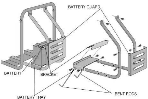
FIGURE 7: BATTERY FRAME ASSEMBLY
NOTE: Use a battery rated at 12V — 18-35AH or more. Battery dimensions can be no greater than 8" X 5-1/4" X 7" (L X W X H).
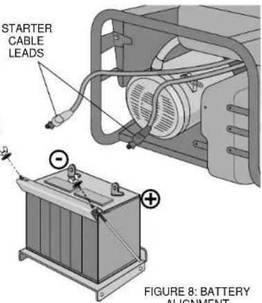
FIGURE 8: BATTERY ALIGNMENT
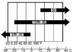
FIGURE 9: ENGINE OIL AND AMBIENT TEMPERATURE
Pre-operation check
Before starting the generator, check the oil and fuel levels. Test the GFCI outlets as directed on page 1 of this manual. Be sure that the air cleaner is functioning. Check that battery terminals are tight and un-corroded. Follow the guidelines below when adding oil and fuel.
ENGINE OIL
NOTE: There is no oil in the engine crankcase when the generator is shipped. You must add oil before starting the engine. Check the oil level before each use with the generator on a level surface and the engine stopped.
Engine oil is a major factor affecting engine performance and service life. Non-detergent and 2-stroke oils will damage the engine and are not recommended. Use 4-stroke motor oil that meets or exceeds the requirements for API service classification SF or SG. Always check the API SERVICE label on the oil container to be sure it includes the letters SF or SG. SAE 10W-30 is recommended for general, all-temperature use. Other viscosities shown in figure 9 may be used when the average temperature in your area is within the indicated range.
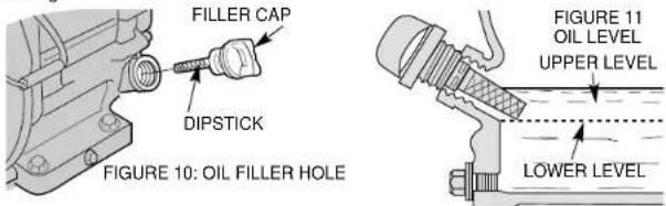
CHECKING THE OIL (FIGURES 10 AND 11)
- Remove the oil filler cap and wipe the dipstick clean.
- Check the oil level by inserting the dipstick into the filler neck without screwing it in.
- If the test shows no oil markings, the oil is low.
- If the level is low, add the recommended oil to the upper mark on the dipstick.
OIL CAPACITY
DEWALT Model Quarts Liters
DG2900.63.60
DG4300 1.16 1.10
DG6000/DG6000E 1.16 1.10
DG7000/DG7000E 1.16 1.10
NOTE: If the oil level is too low, the oil alert system will shutdown the engine and prevent engine from restarting.
FUEL
⚠ WARNING! Gasoline is flammable and its vapor is explosive. To prevent fire or explosion, follow the guidelines below:
- Keep fuel out of the reach of children.
- Refuel the generator in well-ventilated area. Do not refuel while engine is running or hot. Disconnect all electrical loads and shut off the engine before refueling.
- Do not overfill the fuel tank. Always allow room for fuel vapors to expand. If you overfill the tank, fuel can overflow onto the hot engine. This can cause fire or explosion. After refueling, tightly close the fuel tank cap.
- Do not spill fuel. Fuel or fuel vapor may ignite. If fuel spills, make sure that the area is dry before starting the engine.
- Never smoke in the refueling area. Never allow open flames or sparks in area.
- Store fuel in an approved container. Store fuel in a well ventilated area free of open flames or sparks.
FUEL TANK CAPACITY
DeWALT Model Gallons Liters
DG2900 3.0 11.4
DG4300 5.0 18.9
DG6000/DG6000E 5.0 18.9
DG7000/DG7000E 5.0 18.9
Check the fuel gauge located on the top of the generator near the fuel tank and refill the tank if the fuel level is low. Refuel carefully to avoid spilling fuel. Do not fill above the shoulder of the fuel strainer (figure 12).
Use unleaded gasoline with a pump octane rating of 86 or higher. The Honda engine is certified to operate on unleaded gasoline. Unleaded gasoline produces fewer engine and spark plug
deposits and extends exhaust system line. Never use state or contaminated gasoline. Avoid getting dirt or water in the fuel tank. Always keep the fuel strainer in place while refueling.
FIGURE 12:
FUEL STRAINER
OXYGENATED FUELS
Some conventional gasolines are blended with alcohol or an ether compound. These gasolines are collectively referred to as oxygenated fuels. To meet clean air standards, some areas of the United States and Canada use oxygenated fuels to help reduce emissions.
If you use an oxygenated fuel, be sure it is unleaded and meets the minimum octane rating requirements. Before using an oxygenated fuel, try to confirm the fuel's contents. Some states/provinces required this information to be posted on the pump. The following are the EPA approved percentages of oxygenates:
Ethanol (ethyl or grain alcohol) 10% by volume. You may use gasoline containing up to 10% ethanol by volume. Gasoline containing ethanol may be marketed under the name "Gasohol."
MTBE (methyl tertiary butyl ether) 15% by volume. You may use gasoline containing up to 15% MTBE by volume.
Methanol (methyl or wood alcohol) 5% by volume. You may use gasoline containing up to 5% methanol by volume as long as it also contains cosolvents and corrosion inhibitors to protect the fuel system. Gasoline containing more than 5% methanol by volume may cause starting and/or performance problems. It may also damage metal, rubber, and plastic parts of the generator or your fuel system.
If you notice any undesirable operating symptoms, try another service station or switch to another brand of gasoline.
NOTE: Fuel system damage or performance problems resulting from the use of an oxygenated fuel containing more than the percentages of oxygenates mentioned above are not covered under warranty.
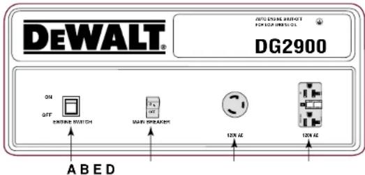
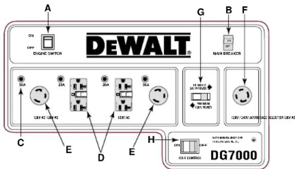
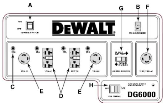
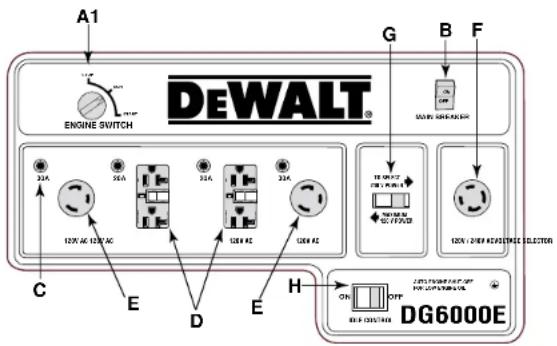
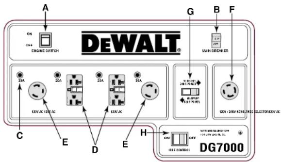
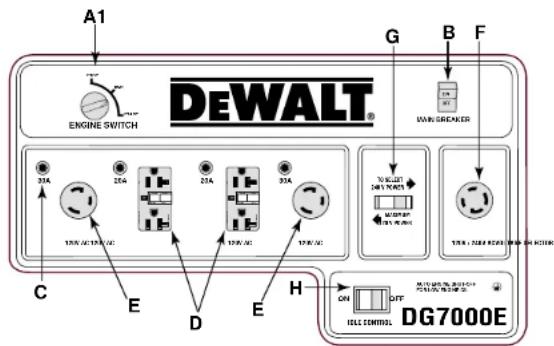
Control Panel
Refer to figure 13 on page 4-5 for layout of generator control panels.
ENGINE ON/OFF SWITCH
The engine switch (A) must be in the on position to start. To stop the engine, place switch in the off position. For electric start models (DG6000E and DG7000E), place the engine switch in the stop position to stop the generator. See the section titled "OPERATION" beginning on page 6 of this manual for complete starting and stopping instructions.
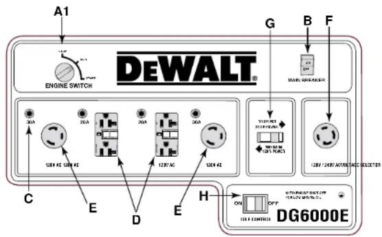
ELECTRIC START
DG6000E and DG7000E are equipped with an electric start. On these generators, the engine switch (A1) can be placed in three positions; stop, run and start. See the section titled "OPERATION" beginning on page 6 of this manual for complete starting information.
MAIN BREAKER
The main breaker (B) protects the alternator. Overloading the generator will trip the main circuit breaker. A short circuit in an electrical device being powered can also trip the main circuit
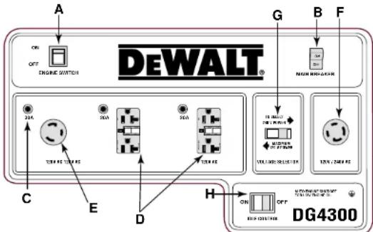
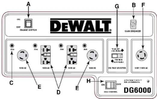
FIGURE 13: CONTROL PANEL LAYOUTS
A. Engine On/Off Switch
A1. Electric Start Engine Switch
B. Main Breaker
C. Individual Thermal Breakers
D. GFCI Duplex Receptacles (120V)
E. Twist-Lock Receptacles (120V)
F. Twist-Lock Receptacles (120V/240V)
G. Voltage Selector Switch
H. Idle Control Switch
flowchart
graph TD
    A["Engine Switch"] --> B["DEWALT®"]
    B --> C["12A 12A 12A 12A"]
    B --> D["12A 12A 12A 12A"]
    B --> E["12A 12A 12A 12A"]
    B --> F["12A 12A 12A 12A"]
    B --> G["12A 12A 12A 12A"]
    B --> H["12A 12A 12A 12A"]
    B --> I["12A 12A 12A 12A"]
    B --> J["12A 12A 12A 12A"]
    B --> K["12A 12A 12A 12A"]
    B --> L["12A 12A 12A 12A"]
    B --> M["12A 12A 12A 12A"]
    B --> N["12A 12A 12A 12A"]
    B --> O["12A 12A 12A 12A"]
    B --> P["12A 12A 12A 12A"]
    B --> Q["12A 12A 12A 12A"]
    B --> R["12A 12A 12A 12A"]
    B --> S["12A 12A 12A 12A"]
    B --> T["12A 12A 12A 12A"]
    B --> U["12A 12A 12A 12A"]
    B --> V["12A 12A 12A 12A"]
    B --> W["12A 12A 12A 12A"]
    B --> X["12A 12A 12A 12A"]
    B --> Y["12A 12A 12A 12A"]
    B --> Z["12A 12A 12A 12A"]
    B --> AA["12A 12A 12A 12A"]
    B --> AB["12A 12A 12A 12A"]
    B --> AC["12A 12A 12A 12A"]
    B --> AD["12A 12A 12A 12A"]
    B --> AE["12A 12A 12A 12A"]
    B --> AF["12A 12A 12A 12A"]
    B --> AG["12A 12A 12A 12A"]
    B --> AH["12A 12A 12A 12A"]
    B --> AI["12A 12A 12A 12A"]
    B --> AJ["12A 12A 12A 12A"]
    B --> AK["12A 12A 12A 12A"]
    B --> AL["12A 12A 12A 12A"]
    B --> AM["12A 12A 12A 12A"]
    B --> AN["12A 12A 12A 12A"]
    B --> AO["12A 12A 12A 12A"]
    B --> AP["12B/40V AC/DC/DC/DC/DC/DC/DC/DC/DC/DC/DC/DC/DC/DC/DC/DC/DC/DC/DC/DC/DC/DC/DC/DC/DC/DC/DC/DC/DC/DC/DC/DC/DC/DC/DC/DC/DC/DC/DC/DC/DC/DC/DC/DC/DC/DC/DC/DC/DC/DC/DC/ DC/DC/DC/DC/DC/DC/DC/DC/DC/DC/DC/DC/DC/DC/DC/DC/DC/DC/DC/DC/DC/DC/DC/DC/DC/DC/DC/DC/DC/DC/DC/DC/DC/DC/DC/DC/DC/DC/DC/DC/DC/DC/DC/DC/DC/DC/DC/DC/DC/DC/AC/DG7000"]
    style A fill:#f9f,stroke:#333
    style B fill:#ccf,stroke:#333
    style C fill:#cfc,stroke:#333
    style D fill:#cfc,stroke:#333
    style E fill:#cfc,stroke:#333
    style F fill:#cfc,stroke:#333
    style G fill:#cfc,stroke:#333
    style H fill:#cfc,stroke:#333
    style I fill:#cfc,stroke:#333
    style AJ fill:#cfc,stroke:#333
    style AK fill:#cfc,stroke:#333
    style AL fill:#cfc,stroke:#333
    style AM fill:#cfc,stroke:#333
    style AN fill:#cfc,stroke:#333
    style AO fill:#cfc,stroke:#333
    style AP fill:#cfc,stroke:#333
    style AQ fill:#cfc,stroke:#333
    style AR fill:#cfc,stroke:#333
    style AS fill:#cfc,stroke:#333
    style AT fill:#cfc,stroke:#333
    style AU fill:#cfc,stroke:#333
    style AV fill:#cfc,stroke:#333
    style AW fill:#cfc,stroke:#333
    style AX fill:#cfc,stroke:#333
    style AY fill:#fcc,stroke:#333
    style AZ fill:#fcc,stroke:#333
    style BA fill:#fcc,stroke:#333
    style BB fill:#fcc,stroke:#333
    style BC fill:#fcc,stroke:#333
    style BD fill:#fcc,stroke:#333
    style BE fill:#fcc,stroke:#333
    style BF fill:#fcc,stroke:#333
    style BG fill:#fcc,stroke:#333
    style BH fill:#fcc,stroke:#333
    style BI fill:#fcc,stroke:#333
    style BJ fill:#fcc,stroke:#333
    style BK fill:#fcc,stroke:#333
    style BL fill:#fcc,stroke:#333
    style BM fill:#fcc,stroke:#333
    style BN fill:#fcc,stroke:#333
    style BO fill:#fcc,stroke:#333
    style BP fill:#fcc,stroke:#333
    style BPN fill:#fcc,stroke:#333
    style BPQ fill:#fcc,stroke:#333
breaker. If the main breaker trips, disconnect the electrical loads from all receptacles. Push the circuit breaker switch to the on position. If the main breaker turns to the off position when no electrical loads are connected, see a service technician.
RECEPTACLE THERMAL BREAKERS
The receptacle circuit breakers protect the receptacles. Overloading the generator will trip the thermal circuit breaker. If an individual thermal breaker selector switch (C) moves to the tripped position as shown in figure 14, disconnect the electrical load from the receptacle. Let the circuit breaker cool down. Push the individual thermal breaker selector switch (C) to reset.
NOTE: The 120/240-Volt twist-locking receptacles do not have individual thermal breakers. The receptacle is protected by the main breaker. High ambient temperatures can cause thermal breakers to trip.

FIGURE 14
RECEPTACLE
THERMAL BREAKERS
GFCI DUPLEX RECEPTACLES (120V)
All models have at least one 120-volt ground fault circuit interrupter (GFCI). These models have 2 ground fault circuit interrupter: DG6000/DG6000E, DG4300, DG7000/DG7000E.
The GFCI protects you against hazardous electrical shock caused when your body becomes a path through which electricity travels to the ground. This could happen when you touch a cord of an appliance that is "live" through faulty mechanism, dampness or worn insulation, etc. See the section titled "SAFETY INSTRUCTIONS FOR GENERATORS" that begins on page 1 to read more about GFCI Receptacles.
TWIST-LOCKING RECEPTACLES (120-VOLT)
All models have at least one 120-Volt twist-locking receptacle.
| 120-Volt 120-Volt20 Amp 30 Amp(NEMA L5-20R) (NEMA L5-30R) |
| DG2900 1 |
| DG4300 1 |
| DG6000/DG6000E 2 |
| DG7000 /DG7000E 2 |
TWIST-LOCKING RECEPTACLES (120/240-VOLT)
The DG4300, DG6000, DG6000E, DG7000, and DG7000E models have a 120/240-Volt twist-locking receptacle.
| 120/240-Volt20 Amp 30 Amp(NEMA L14-20R) | 120/240-Volt(NEMA L14-30R) | |
| DG4300 | 1 | |
| DG6000/DG6000E | 1 | |
| DG7000/DG7000E | 1 |
VOLTAGE SELECTOR SWITCH
This switch allows the generator to operate in either single voltage (120-Volt) or dual voltage (120/240-Volt) mode. In single voltage mode only the 120-Volt duplexes and twist-locking receptacles are powered. The full rated power of the generator is shared between the 120-Volt receptacles. In dual voltage mode both the 120-Volt and 120/240-Volt receptacles are powered; however, only half the rated power is available at the 120-Volt receptacles. Full power is available at the 120/240-Volt twist-locking receptacle.
NOTE: Do not move the voltage selector switch while powering electrical devices. Disconnect all electrical loads before moving the switch. Failure to disconnect electrical loads can damage the switch.
IDLE CONTROL SWITCH
The DG4300, DG6000, DG6000E, DG7000 and DG7000E models have an idle control switch (H). The idle control switch automatically reduces engine speed 8 seconds after all electrical
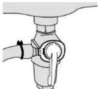
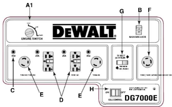
FIGURE 15: FUEL VALVE PETCOCK OPEN
FIGURE 16:
CHOKE LEVER CLOSED
FIGURE 17:
CHOKE LEVER OPEN
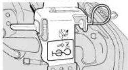
loads attached to the generator have been turned off. The engine automatically returns to full speed when an electrical load is turned back on.
To turn the idle control feature on, turn on the idle control switch. Using this feature is recommended while the generator is running to minimize fuel consumption. To avoid extended engine warm-up periods, place the switch in the off position when starting the engine and until the engine reaches operating temperature.
OPERATION
Starting Generator — Recoil Start
⚠ WARNING: Before starting the generator, be sure that you read and understand all the safety and operating instructions in this manual.
-
Disconnect all electrical loads from the generator and place the main circuit breaker in the off (open) position.
-
Turn the idle control switch (figure 13H) off.
NOTE: The DEWALT models DG4300, DG6000, DG6000E, DG7000 and DG7000E have the idle control feature. Model DG2900 does not have this feature.
-
Open the fuel valve by turning the petcock clockwise to the vertical position as shown in figure 15.
-
If the engine is cold, pull the choke lever out to the closed position shown in figure 16. If the engine is hot, set choke to open position shown in figure 17.
-
Turn engine switch (figure 13A) on.
-
Pull the starter grip slowly until you feel compression then pull briskly.
NOTE: Do not allow the starter grip to snap back. Return it slowly by hand.
NOTE: If the oil level in the engine is low, the engine will not start. If the engine does not start, check the oil level and add oil as needed.
NOTE: To ensure maximum oil lubrication, place the generator on a level surface.
-
As the engine warms up, move the choke lever to the open position shown in figure 17.
-
Allow the engine to warm up for a few minutes. Then place the main breaker (figure 13B) in the on (closed) position. Attach electrical loads.
Starting the Generator — Electric Start
⚠ WARNING: Before starting the generator, be sure you read and understand all the safety and operating instructions in this manual.
-
Follow steps 1 through 5 of the recoil start section.
-
Turn starter switch to the start position. See Figure 18.
-
Hold the switch in the start position until the engine starts.
NOTE: Do not hold the switch in the start position for more than 5 seconds. If the engine does not start, wait 10 seconds before re-trying. Failure to follow these instructions may result in damage to the starter motor due to overheating.
- When the engine starts, release the switch, allowing it to return to the run position.
NOTE: Do not turn the switch to the start position while the generator is running.
-
As the engine warms up, move the choke lever to the open position as shown in figure 17.
-
Allow the engine to warm up for a few minutes before placing the main breaker (figure 13B) in the on (closed) position. Attach electrical loads.
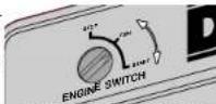
FIGURE 18: ELECTRIC START SWITCH
Stopping the Generator
To stop the engine in an emergency, move the engine switch to the off position. For electric start models (DG6000E and DG7000E) turn the engine switch to the stop position.
To Stop the Generator in Normal Use:
- Turn off and disconnect all electrical loads attached to the generator.
- Turn the engine switch off. For electric start models (DG6000E and DG7000E), turn the engine switch to stop.
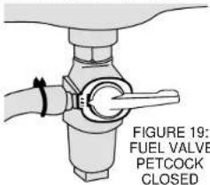
- Close the fuel valve by turning petcock counterclockwise to the horizontal position shown in figure 19.
Engine Speed
Generators require a fixed engine speed to maintain the correct voltage. Engine speed is controlled by the governor which automatically adjusts to varying loads on the engine to maintain a constant speed of 3600-3700 rpm.
NOTE: Do not adjust the governor setting of this generator. It has been set at the factory for optimum performance. Tampering may cause damage to the generator and voids the warranty. The governor may only be adjusted by an authorized service center.
Operating Heavy Loads
Limit operations requiring the maximum rated output.
| DEWALT | Model | Maximum | Output |
DG2900 2900 Watts
DG4300 4300 Watts
DG6000/DG6000E 6000 Watts
DG7000/DG7000E 7000 Watts
For continuous operation do not exceed the continuous rated output.
DEWALT Model Continuous Output
DG2900 2400 Watts
DG4300 3800 Watts
DG6000/DG6000E 5000 Watts
DG7000/DG7000E 6000 Watts
DO NOT exceed the current limit specified on the control panel for any receptacle.
High Altitude Operating
At high altitude, the standard carburetor air-fuel mixture will be too rich. Performance will decrease and fuel consumption will increase. A very rich mixture will also foul the spark plug and cause hard starting.
High altitude performance can be improved by specific modifications to the carburetor. If you always operate your engine at altitudes above 1,800 meters (6,000 feet), have your authorized service center perform a carburetor modification.
Even with a carburetor modification, engine horsepower will decrease about 3.5% for each 300 meter (1,000 foot) increase in altitude. The effect of altitude on horsepower will be greater than this if no carburetor modification is made. A decrease in engine horsepower will decrease the power output of the generator.
NOTE: When the carburetor has been modified for high altitude operation, the air-fuel mixture will be too lean for low altitude use. If the generator is used at low altitudes after a carburetor modification, the carburetor may cause the engine to overheat and result in serious engine damage. For use at low altitudes, have your authorized service center return the carburetor to original factory specifications.
High and Low Temperature Operation
Air temperature affects generator output. Output drops 1% for each 10^ F temperature rise above 60^ F. Very low temperature may cause the engine to be hard to start.
Charging Portable Power Tool Batteries
⚠ WARNING! Condenser type chargers should not be used with portable generators. Irregular generator power could cause a condenser type charger to fail. DeWALT has produced condenser type chargers in the past. (DW9104 and DW9106). If you have any questions regarding the use of a DeWALT Charger with a generator, please call 1-800-4DeWALT.
NOTE: Other battery charger manufacturers have and still produce condenser type chargers. Please contact manufacturer to see if it is safe to use chargers with portable generators.
Troubleshooting
If the engine does not start
-
Check the fuel tank for sufficient fuel. Refill with fresh gasoline if necessary.
-
Check the engine oil. Fill to the upper limit with fresh oil.
-
Ensure that the fuel petcock is open. The fuel petcock is open when the lever is perpendicular to the ground (straight up and down as in figure 15).
-
Check that the spark plug cap is securely attached to the spark plug.
-
Inspect the air filter. Clean or replace it if necessary.
-
Disconnect all electrical loads from the generator, and turn the engine switch on.
-
Follow the starting procedures in this manual on page 6.
If the engine still does not start
-
Pull the starter handle 5-6 times (for recoil start models only).
-
Remove and inspect the spark plug.
If the spark plug is dry:
-
Ensure that there is fresh fuel in the tank and that the fuel petcock is open.
-
Reinstall the spark plug and spark plug cap.
-
Try to start the engine again by following the starting procedures in this manual on page 6.
-
If the engine fails to start, take the generator to an authorized DEWALT or Honda service center.
If the spark plug is wet.
-
Clean, gap, or replace the spark plug.
-
Reinstall the spark plug and spark plug cap.
-
Try to start the engine again by following the starting procedures in this manual on page 6.
-
If the engine fails to start, take the generator to an authorized D EWALT or Honda service center.
If there is no power to the receptacles
-
Turn the circuit breaker switches off and disconnect all electrical loads from the generator.
-
Turn the circuit breakers on and test the GFCI's by following the procedures in this manual on page 1.
-
Place the voltage selector to the 120 Volt only positions (unless you are using a tool that requires 240 Volts).
-
Turn the idle control switch off.
-
Turn the circuit breaker(s) off and reconnect the electrical loads. Be sure that the plugs are securely connected to the receptacles.
-
Turn the circuit breaker(s) on.
-
If there is still no power at the receptacles, take the generator to an authorized D EWALT service center. To locate a DEWALT service center nearest to you, call 1-800-4-DEWALT
MAINTENANCE
Importance of Maintenance
Good maintenance is essential for safe, economical, and trouble-free operation. It will also help reduce air pollution.
⚠ WARNING! Improper maintenance or failure to correct a problem before operation can cause malfunction, serious injury, or death. Always follow the inspection and maintenance recommendation and schedules in this user's manual.
The following pages include a maintenance schedule, routine inspection procedures, and simple maintenance procedures using basic hand tools, to help you properly care for your generator. If you are not comfortable with any maintenance procedure, have the generator serviced by a professional technician.
Maintenance, replacement, or repair of the emission control devices and system may be performed by any engine repair establishment or individual, using parts that are "certified" to EPA standards.
Maintenance Safety
⚠ WARNING! Always follow the procedures and precautions in the owner's manual. Failure to properly follow maintenance instructions and precautions can lead to serious injury or death.
SAFETY PRECAUTIONS
⚠️ CAUTION: Make sure that the engine is off before you begin any maintenance or repairs. This will eliminate several potential hazards, including:
- carbon monoxide poisoning from engine exhaust. Be sure there is adequate ventilation whenever you operate the engine.
- burns from hot parts. Let the engine and exhaust system cool before you touch it to prevent burns.
- injury from moving parts. Wear appropriate clothing, tie back long hair, and stay alert around the generator to prevent injury from moving parts.
Read the instructions before you begin, and make sure you have the tools and skills required. Your authorized service center knows your generator best and is fully equipped to do maintenance and repair. To ensure the best quality and reliability, use only new genuine parts or their equivalents for repair or replacement.
⚠ CAUTION: To reduce the possibility of fire or explosion, be careful when working around gasoline. Use only a nonflammable solvent, not gasoline, to clean parts. Keep tobacco products, sparks, and flames away from all fuel related parts.
Emission Control System
SOURCE OF EMISSIONS
The combustion process produces carbon monoxide, oxides of nitrogen, and hydrocarbons. Control of hydrocarbons and oxides of nitrogen is very important because, under certain conditions, they react to form photochemical smog when subjected to sunlight. Carbon monoxide does not react in the same way, but it is toxic.
A Honda engine powers your DEWALT Generator. Honda uses lean carburetor settings and other systems to reduce the emissions of carbon monoxide, oxides of nitrogen, and hydrocarbons.
THE U.S. AND CALIFORNIA CLEAN AIR ACTS
EPA and California regulations require all manufacturers to furnish written instructions describing the operation and maintenance of emissions control systems.
The following instructions and procedures must be followed in order to keep the emissions from your Honda Engine within the emissions standards.
TAMPERING AND ALTERING
Tampering with or altering the emission control system may increase emissions beyond the legal limit. Among those acts that constitute tampering are:
- removal or alteration of any part of the intake, fuel, or exhaust systems.
• altering or defeating the governor linkage or speed-adjusting mechanism to cause the engine to operate outside its design parameters.
PROBLEMS THAT MAY AFFECT EMISSIONS
If you are aware of any of the following symptoms, have your engine inspected and repaired by your authorized service center.
• Hard starting or stalling after starting
- Rough idle
- Misfiring or backfiring under load
• Afterburning (Backfiring)
- Black exhaust smoke or high fuel consumption
REPLACEMENT PARTS
The emission control systems on your Honda Engine were designed, built, and certified, to conform with EPA and California Emission Regulations. We recommend the use of genuine Honda parts whenever you have engine maintenance done. These original-design replacement parts are manufactured to the same standards as the original parts, so you can be confident of their performance. The use of replacement parts that are not of the original design and quality may impair the effectiveness of your emissions control system.
A manufacturer of an aftermarket part assumes the responsibility that the part will not adversely affect emissions performance. The manufacturer or rebuilder of the part must certify that use of the part will not result in a failure of the engine to comply with emission regulations.
Maintenance Schedule
The Periodic Maintenance Schedule below lists basic maintenance intervals for the engine and generator. Please read the detailed maintenance procedures for the engine described in the Owner's Manual. Replacement copies of these manuals can be ordered from DEWALT. Please call 1-800-4 DEWALT.
NEW MACHINES
Change the engine oil and replace the air filter after the first 20 hours of operation.
PERIODIC MAINTENANCE SCHEDULE
Daily Every Every Every
Before 3 mos./ 6 mos./ year or Starting 50 hrs. 100 hrs. 300 h
| *Engine Oil | Check Level | X | |||
| Change | X | ||||
| *Air Cleaner | Check | X | |||
| Clean | X (1) | ||||
| Battery Terminals | Check | X | |||
| Clean | X (1) | ||||
| *Sediment Cup | Clean | X | |||
| *Spark Plug | Clean-Readjust | X | |||
| Replace | X | ||||
| Spark Arrester | Clean | X | |||
| Vibration Isolators | Check-Tighten | X |
Daily Every Every Every
Before 3 mos./ 6 mos./ year or
| *Valve | Check | X (2) |
| Clearance | -Readjust | X (2) |
| *Fuel tank & filter Clean | X (2) | |
| *Fuel line | Check | Every 2 years (replace if necessary)(2) |
* Emission related items
(1) Service more frequently when used in dusty areas
(2) An authorized DEWALT Service Center should service these items or authorized Honda Service Center.
For commercial use, log hours of operation to determine proper maintenance intervals.
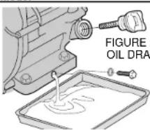
ENGINE OIL CHANGE
Drain the oil while the engine is warm to assure complete and rapid draining.
- Remove oil fill plug and drain plug to drain oil as shown in figure 20.
- Reinstall drain plug. Tighten the plug securely.
- Fill engine crankcase with recommended oil (See page 3). Check oil level (Figure 21).
- Reinstall oil filler cap.
OIL CAPACITY
| DEWALT Model | Quarts | Liters |
 | 20:IN | 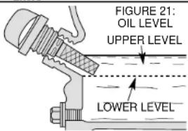 |
| DG2900 | .63 | .60 |
| DG4300 | 1.16 | 1.10 |
| DG6000/DG6000E | 1.16 | 1.10 |
| DG7000/DG7000E | 1.16 | 1.10 |
Wash your hands with soap and water after handling used oil.
Please dispose of used motor oil and containers in a manner that will not harm the natural environment. We suggest you take it in a sealed container to your local service station or recycling center for reclamation. Do not throw it in the trash, pour it on the ground or down the drain.
NOTE: Never operate the generator without oil cap tightly secured. Failure to do so could cause oil to spill out of the engine.
AIR FILTER
Adirty air cleaner will restrict airflow to the carburetor. To prevent carburetor malfunction, service the air filter regularly. Service more frequently when operating the generator in extremely dusty areas.
⚠ WARNING!: Using gasoline or flammable solvent to clean the filter element can cause a fire or explosion. Use only soapy water or nonflammable solvent.
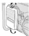
FIGURE 23: AIR FILTER REMOVAL
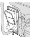

FIGURE 24: AIR FILTER CLEANING
NOTE: Never run the generator without the air cleaner. Rapid engine wear will result.
- Unsnap the air cleaner cover clips, remove the air cleaner cover, and remove the element as shown in figure 22 and 23.
- Wash the element in a solution of household detergent and warm water, then rinse thoroughly, or wash in nonflammable or high flash point solvent. Allow the element to dry thoroughly.
- Soak the element in clean engine oil and squeeze out the excess oil as shown in figure 24. The engine will smoke during initial start-up if too much oil is left in the element.
- Reinstall the air filter element cover.
FUEL SEDIMENT CUP CLEANING
The sediment cup prevents dirt or water, which may be in the fuel tank from entering the carburetor. If the engine has not been run for a long time, the sediment cup should be cleaned.
- Turn the fuel valve to the off position (horizontal to the ground). Remove the sediment cup, and O-ring as shown in figure 25.
- Clean the sediment cup, and the O-ring, in nonflammable or high flash point solvent.
- Reinstall O-ring, and sediment cup.
- Turn the fuel valve on and check for fuel leaks.
SPARK PLUG SERVICE
To service the spark plug, you will need a spark plug wrench like the one included with generator. Use recommended spark plugs: BPR6ES(NGK), W20EPR-U(DENSO). To ensure proper engine operation, the spark plug must be properly gapped and free of deposits.
⚠️ CAUTION: If the engine has been running, the muffler will be very hot. Be careful not to touch the muffler. Be sure to allow the engine to cool before you touch the spark plug.
- Remove the spark plug cap.
- Clean any dirt from around the spark plug base.
- Use a spark plug wrench to remove the spark plug.
- Visually inspect the spark plug. Replace it if the insulator is cracked or chipped. Clean the spark plug with a wire brush if you plan to reuse it.
- Measure the plug gap with the feeler gauge. Correct as necessary by carefully bending the side electrode (figure 26). The gap should be: 0.70-0.80 mm (0.028-0.031 in)
- Check that the spark plug washer is in good condition. If it is not, thread the spark plug in by hand to prevent cross threading.
- After the spark plug is seated, tighten with a spark plug wrench to compress the washer. If you are installing a new spark plug, tighten the spark plug 1/2 turn after it seats to compress the washer. If you are reinstalling a used spark plug, tighten 1/8–1/4 turn after the spark plug seats to compress the washer.
NOTE: The spark plug must be securely tightened. An improperly tightened spark plug can become very hot and could damage the engine. Never use spark plugs which have an improper heat range. Use only the recommended spark plugs or equivalent.
SPARK ARRESTER
⚠️ CAUTION: If the generator has been running, the muffler will be very hot. Allow cooling before proceeding.
NOTE: The spark arrester must be serviced every 100 hours to maintain its efficiency.
FIGURE 25: FUEL CUP CLEANING
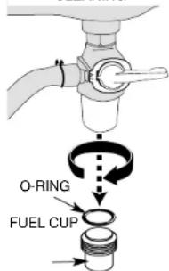
FIGURE 26: SPARK PLUG GAP
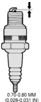
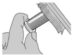
FIGURE 27: REMOVING SPARK ARRESTER
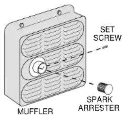
FIGURE 28
CLEANING SPARK ARRESTER
natural_image
Close-up of hands holding a cylindrical mechanical component (no visible text or symbols)- Using a Phillips-head screwdriver, remove the spark arrester screw as shown in figure 27.
- Use brush to remove carbon deposits from the spark arrester screen as shown in figure 28. Inspect the spark arrester screen for holes or tears. Replace the spark arrester if necessary.
Full Two Year Warranty
DEWALT heavy duty generators are warranted for two years from the date of purchase. We will repair, without charge, any defects due to faulty materials or workmanship. For warranty repair information, call 1-800-4-DEWALT. This warranty does not apply to accessories or damage caused where repairs have been made or attempted by others. This warranty gives you specific legal rights and you may have other rights which vary in certain states or provinces.
Gasoline engines are covered by the product manufacturer's warranty.
FREE WARNING LABEL REPLACEMENT: If your warning labels become illegible or are missing, call 1-800-4-DEWALT for a free replacement.
COMPREND LA GÉNÉRATRICE, LE NÉCESSAIRE DE ROUES ET DE POIGNÉES, LE CROCHET DE LEVAGE ET LA CLÉ À BOUGIE.
natural_image
Line drawing of a portable electricity generator (DG7000) with wheels and control panel, no text or symbols present.MOTEUR OHV GX HONDA 13 HP
COMMANDE DE RALENTI. ARRÊT AVEC NIVEAU D'HUILE BAS
flowchart
graph TD
    A["Engine Switch"] --> B["Main Breaker"]
    B --> C["Control Panel DG7000"]
    C --> D["Control Panel"]
    D --> E["Main Breaker"]
    E --> F["Control Panel"]
    style A fill:#f9f,stroke:#333
    style B fill:#ccf,stroke:#333
    style C fill:#cfc,stroke:#333
    style D fill:#fcc,stroke:#333
    style E fill:#cff,stroke:#333
natural_image
Close-up of hands performing a mechanical tool with a threaded component (no text or symbols visible)natural_image
Line drawing of a portable electricity generator (DG7000) with visible control panel and wheels, no text or symbols present.MOTOR HONDA OHV GX DE 13 HP
CONTROL DE ESPERA
APAGADO AUTOMÁTICO DEBIDO A BAJO NIVEL DE ACEITE
AMORTIGUADOR EXTRA SILENCIOSO
Product Specifications
natural_image
Technical diagram of a mechanical assembly with flanged ends and a rectangular housing (no text or symbols)FIGURA 4: PARTES DEL MARCO DE LA BATERÍA, ENCENDIDO ELÉCTRICO ÚNICAMENTE
natural_image
Mechanical assembly diagrams showing two configurations of a lever mechanism (no text or labels)Accesorios
natural_image
Diagram of a mechanical valve assembly with a handle and lever (no text or labels)natural_image
Close-up of hands holding a mechanical component, possibly a tool or tool, with no visible text or symbols.Póliza de Garantía
Eje Lázaro Cárdenas No. 18 Local D, Col. Obrera 588-9377
MERIDA
Calle 63 #459-A (91 99) 23 54 90
MONTERREY
Av. Francisco I. Madero Pte. 1820-A (91 83) 72 11 25
PUEBLA
17 Norte #205 (91 22) 46 37 14
QUERETARO
Av. Madero 139 Pte. (91 42) 14 16 60
SAN LOUIS POTOSI
Pedro Moreno #100 Centro (91 48) 14 25 67
TORREON
Blvd. Independencia, 96 pte. (91 17) 16 52 65
VERACRUZ
Prolongación Diaz Miron #4280 (91 29) 21 70 16
VILLAHERMOSA
Constitucion 516-A (91 93) 12 53 17