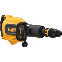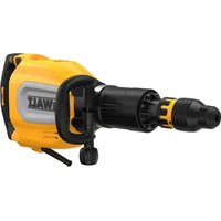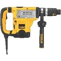
D25651K - Hammer DEWALT - Free user manual and instructions
Find the device manual for free D25651K DEWALT in PDF.


User questions about D25651K DEWALT
0 question about this device. Answer the ones you know or ask your own.
Ask a new question about this device
Download the instructions for your Hammer in PDF format for free! Find your manual D25651K - DEWALT and take your electronic device back in hand. On this page are published all the documents necessary for the use of your device. D25651K by DEWALT.
USER MANUAL D25651K DEWALT
1-9/16" (40 mm) SDS Max and Spline Combination Hammers
D25601, D25603, D25651
1-3/4" (45 mm) SDS Max and Spline Combination Hammers
D25831, D25851
SDS Max and Spline Chipping Hammers
D25501, D25553
Marteaux mixtes, SDS Max et cannelures, 40 mm (1–9/16 po)
D25601, D25603, D25651
Marteaux mixtes, SDS Max et cannelures, 45 mm (1–3/4 po)
D25831, D25851
Marteaux burineurs, SDS Max et cannelures
D25501, D25553
Definitions: Safety Alert Symbols and Words
This instruction manual uses the following safety alert symbols and words to alert you to hazardous situations and your risk of personal injury or property damage.
DANGER: Indicates an imminently hazardous situation which, if not avoided, will result in death or serious injury.
WARNING: Indicates a potentially hazardous situation which, if not avoided, could result in death or serious injury.
CAUTION: Indicates a potentially hazardous situation which, if not avoided, may result in minor or moderate injury.
(### without word) Indicates a safety related message.
NOTICE: Indicates a practice not related to personal injury which, if not avoided, may result in property damage.
Fig. A
text_image
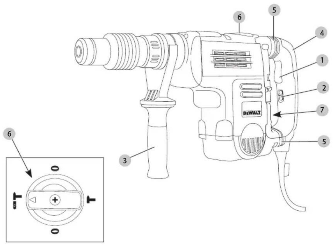
DiWALT 6 5 4 1 2 7 5 3 61 Trigger switch (D25501, D25553, D25601, D25603, D25651) Toggle switch (D25831, D25851)
2 Lock-on slider (D25501, D25553, D25601, D25603, D25651)
3 Side handle
4 Main handle
5 SHOCKS Active Vibration Control® System (D25651, D25601, D25603, D25831, D25851)
6 Mode selector
7 Electronic Speed and impact control dial
WARNING! Read all safety warnings and all instructions. Failure to follow the warnings and instructions may result in electric shock, fire and/or serious injury.

WARNING: To reduce the risk of injury, read the instruction manual.
If you have any questions or comments about this or any DEWALT tool, call us toll free at: 1-800-4-DEWALT (1-800-433-9258).
English
GENERAL POWER TOOL SAFETY WARNINGS
WARNING! Read all safety warnings and all instructions. Failure to follow the warnings and instructions may result in electric shock, fire and/or serious injury.
SAVE ALL WARNINGS AND INSTRUCTIONS FOR FUTURE REFERENCE
The term "power tool" in the warnings refers to your mains-operated (corded) power tool or battery-operated (cordless) power tool.
1) Work Area Safety
a) Keep work area clean and well lit. Cluttered or dark areas invite accidents.
b) Do not operate power tools in explosive atmospheres, such as in the presence of flammable liquids, gases or dust. Power tools create sparks which may ignite the dust or fumes.
c) Keep children and bystanders away while operating a power tool. Distractions can cause you to lose control.
2) Electrical Safety
a) Power tool plugs must match the outlet. Never modify the plug in any way. Do not use any adapter plugs with earthed (grounded) power tools. Unmodified plugs and matching outlets will reduce risk of electric shock.
b) Avoid body contact with earthed or grounded surfaces such as pipes, radiators, ranges and refrigerators. There is an increased risk of electric shock if your body is earthed or grounded.
c) Do not expose power tools to rain or wet conditions. Water entering a power tool will increase the risk of electric shock.
d) Do not abuse the cord. Never use the cord for carrying, pulling or unplugging the power tool. Keep cord away from heat, oil, sharp edges or moving parts. Damaged or entangled cords increase the risk of electric shock.
e) When operating a power tool outdoors, use an extension cord suitable for outdoor use. Use of a cord suitable for outdoor use reduces the risk of electric shock.
f) If operating a power tool in a damp location is unavoidable, use a ground fault circuit interrupter (GFCI) protected supply. Use of a GFCI reduces the risk of electric shock.
3) Personal Safety
a) Stay alert, watch what you are doing and use common sense when operating a power tool. Do not use a power tool while you are tired or under the influence of drugs, alcohol or medication. A moment of inattention while operating power tools may result in serious personal injury.
b) Use personal protective equipment. Always wear eye protection. Protective equipment such as dust mask, non-skid safety shoes, hard hat, or hearing protection used for appropriate conditions will reduce personal injuries.
c) Prevent unintentional starting. Ensure the switch is in the off position before connecting to power source and/or battery pack, picking up or carrying the tool. Carrying power tools with your finger on the switch or energizing power tools that have the switch on invites accidents.
d) Remove any adjusting key or wrench before turning the power tool on. A wrench or a key left attached to a rotating part of the power tool may result in personal injury.
e) Do not overreach. Keep proper footing and balance at all times. This enables better control of the power tool in unexpected situations.
f) Dress properly. Do not wear loose clothing or jewelry. Keep your hair, clothing and gloves away from moving parts. Loose clothes, jewelry or long hair can be caught in moving parts.
g) If devices are provided for the connection of dust extraction and collection facilities, ensure these are connected and properly used. Use of dust collection can reduce dust-related hazards.
4) Power Tool Use and Care
a) Do not force the power tool. Use the correct power tool for your application. The correct power tool will do the job better and safer at the rate for which it was designed.
b) Do not use the power tool if the switch does not turn it on and off. Any power tool that cannot be controlled with the switch is dangerous and must be repaired.
c) Disconnect the plug from the power source and/or the battery pack from the power tool before making any adjustments, changing accessories, or storing power tools. Such preventive safety measures reduce the risk of starting the power tool accidentally.
d) Store idle power tools out of the reach of children and do not allow persons unfamiliar with the power tool or these instructions to operate the power tool. Power tools are dangerous in the hands of untrained users.
e) Maintain power tools. Check for misalignment or binding of moving parts, breakage of parts and any other condition that may affect the power tool's operation. If damaged, have the power tool repaired before use. Many accidents are caused by poorly maintained power tools.
f) Keep cutting tools sharp and clean. Properly maintained cutting tools with sharp cutting edges are less likely to bind and are easier to control.
g) Use the power tool, accessories and tool bits, etc. in accordance with these instructions, taking
into account the working conditions and the work to be performed. Use of the power tool for operations different from those intended could result in a hazardous situation.
5) Service
a) Have your power tool serviced by a qualified repair person using only identical replacement parts. This will ensure that the safety of the power tool is maintained.
Additional Safety Instructions for Rotary Hammers
- Wear ear protectors. Exposure to noise can cause hearing loss.
- Use auxiliary handle(s), if supplied with the tool. Loss of control can cause personal injury.
- Hold power tools by insulated gripping surfaces when performing an operation where the cutting tool may contact hidden wiring or its own cord. Cutting accessory contacting a "live" wire may make exposed metal parts of the power tool "live" and could give the operator an electric shock.
- Use clamps or other practical way to secure and support the workpiece to a stable platform. Holding the work by hand or against your body is unstable and may lead to loss of control.
- Wear safety goggles or other eye protection. Hammering operations cause chips to fly. Flying particles can cause permanent eye damage. Wear a dust mask or respirator for applications that generate dust. Ear protection may be required for most applications.
- Keep a firm grip on the tool at all times. Do not attempt to operate this tool without holding it with both hands. Operating this tool with one hand will result in loss of control. Breaking through or encountering hard materials such as re-bar may be hazardous as well. Tighten the side handle securely before use.
- Do not operate this tool for long periods of time. Vibration caused by hammer action may be harmful to your hands and arms. Use gloves to provide extra cushion and limit exposure by taking frequent rest periods.
- Do not recondition bits yourself. Chisel reconditioning should be done by an authorized specialist. Improperly reconditioned chisels could cause injury.
- Wear gloves when operating tool or changing bits. Accessible metal parts on the tool and bits may get extremely hot during operation. Small bits of broken material may damage bare hands.
- Never lay the tool down until the bit has come to a complete stop. Moving bits could cause injury.
- Do not strike jammed bits with a hammer to dislodge them. Fragments of metal or material chips could dislodge and cause injury.
- Keep the power cord away from the rotating bit. Do not wrap the cord around any part of your body. An electric cord wrapped around a spinning bit may cause personal injury and loss of control.
• Air vents often cover moving parts and should be avoided. Loose clothes, jewelry or long hair can be caught in moving parts.
Additional Safety Information
WARNING: ALWAYS use safety glasses. Everyday eyeglasses are NOT safety glasses. Also use face or dust mask if cutting operation is dusty. ALWAYS WEAR CERTIFIED SAFETY EQUIPMENT:
• ANSI Z87.1 eye protection (CAN/CSA Z94.3),
• ANSI S12.6 (S3.19) hearing protection,
• NIOSH/OSHA/MSHA respiratory protection.
WARNING: Some dust created by power sanding, sanding, grinding, drilling, and other construction activities contains chemicals known to the State of California to cause cancer, birth defects or other reproductive harm. Some examples of these chemicals are:
- lead from lead-based paints,
• crystalline silica from bricks and cement and other masonry products, and
• arsenic and chromium from chemically-treated lumber.
Your risk from these exposures varies, depending on how often you do this type of work. To reduce your exposure to these chemicals: work in a well ventilated area, and work with approved safety equipment, such as those dust masks that are specially designed to filter out microscopic particles.
- Avoid prolonged contact with dust from power sanding, sawing, grinding, drilling, and other construction activities. Wear protective clothing and wash exposed areas with soap and water. Allowing dust to get into your mouth, eyes, or lay on the skin may promote absorption of harmful chemicals.
WARNING: Use of this tool can generate and/or disperse dust, which may cause serious and permanent respiratory or other injury. Always use NIOSH/OSHA approved respiratory protection appropriate for the dust exposure. Direct particles away from face and body.
WARNING: Always wear proper personal hearing protection that conforms to ANSI S12.6 (S3.19)
during use. Under some conditions and duration of use, noise from this product may contribute to hearing loss.
CAUTION: When not in use, place tool on its side can be stable surface where it will not cause a tripping or falling hazard.
• Air vents often cover moving parts and should be avoided. Loose clothes, jewelry or long hair can be caught in moving parts.
ENGLISH
- An extension cord must have adequate wire size
(AWG or American Wire Gauge) for safety. The smaller the gauge number of the wire, the greater the capacity of the cable, that is, 16 gauge has more capacity than 18 gauge. An undersized cord will cause a drop in line voltage resulting in loss of power and overheating. When using more than one extension to make up the total length, be sure each individual extension contains at least the minimum wire size. The following table shows the correct size to use depending on cord length and nameplate ampere rating. If in doubt, use the next heavier gauge. The lower the gauge number, the heavier the cord.
Minimum Gauge for Cord Sets
| Volts | Total Length of Cord in Feet (meters) | ||||
| 120 V 25 (7.6) | 50 (15.2) 100 (30.5) 150 (45.7) | ||||
| 240 V 50 (15.2) | 100 (30.5) 200 (61.0) 300 (91.4) | ||||
| Ampere Rating | American Wire Gauge | ||||
| More Than | Not More Than | ||||
| 0 6 18 | 16 16 14 | ||||
| 6 10 18 | 16 14 12 | ||||
| 10 12 | 16 16 14 12 | ||||
| 12 16 14 12 Not Recommended | |||||
The label on your tool may include the following symbols. The symbols and their definitions are as follows:
V....volts
Hz.....hertz
min......minutes
or DC.....direct current
Class I Construction (grounded)
.../min.....per minute
BPM.....beats per minute
± earthing terminal
⚠️......safety alert symbol
▲......visible radiation
wearrespiratory protection
weareye
protection
O....wearhearing
protection
readall
documentation
SAVE THESE INSTRUCTIONS FOR FUTURE USE
Motor
Be sure your power supply agrees with the nameplate marking. Voltage decrease of more than 10% will cause loss of power and overheating. DeWALT tools are factory tested; if this tool does not operate, check power supply.
COMPONENTS (FIG. A)
WARNING: Never modify the power tool or any part of damage or personal injury could result.
Refer to Figure A at the beginning of this manual for a complete list of components.
INTENDED USE
These heavy-duty rotary hammers have been designed for professional hammerdrilling, and chipping at various work sites (i.e., construction sites). DO NOT use under wet conditions or in presence of flammable liquids or gases.
DO NOT use under wet conditions or in presence of flammable liquids or gases.
These heavy-duty rotary hammers are professional power tools.
DO NOT let children come into contact with the tool. Supervision is required when inexperienced operators use this tool.
ASSEMBLY AND ADJUSTMENTS
WARNING: To reduce the risk of serious personal injury, turn unit off and disconnect it from power source before making any adjustments or removing/installing attachments or accessories. An accidental start-up can cause injury.
Side Handle (Fig. B)
WARNING: To reduce the risk of personal injury, ALWAYS operate the tool with the side handle properly installed and securely tightened. Failure to do so may result in the side handle slipping during tool operation and subsequent loss of control. Hold tool with both hands to maximize control.
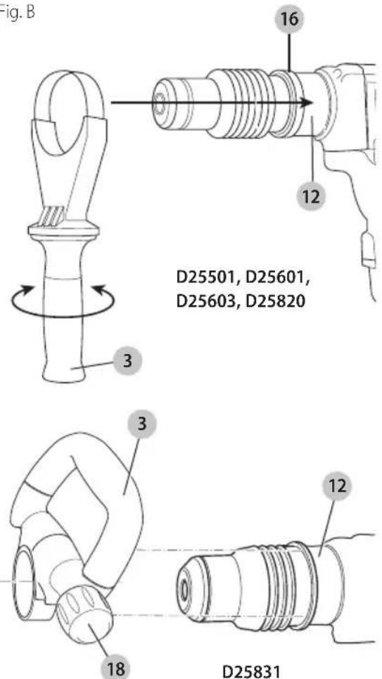
The side handle 3 clamps to the mounting area 12 of the gear case and may be rotated 360° to permit right- or left-hand use. The side handle must be tightened sufficiently to resist the twisting action of the tool if the accessory binds or stalls. Be sure to grip the side handle at the far end to control the tool during a stall.
To loosen side handle, rotate counterclockwise.
English
Fig. B
text_image
Fig. B 16 12 D25501, D25601, D25603, D25820 3 3 18 12 D25831SHOCKS Active Vibration Control® System (Fig. A, F)
D25651, D25601, D25603, D25831, D25851
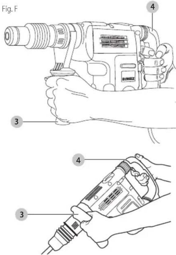
For best vibration control, hold the tool with one hand on the main handle 4 and the other hand on the side handle 3. Apply just enough pressure so the damping device on the main handle is approximately mid stroke. The hammer only needs enough pressure to engage the active vibration control. Applying too much pressure will not make the tool drill or chip faster and active vibration control will not engage.
Inserting and Removing Spline Drive Accessories (Fig. C)
D25553, D25651, D25851
WARNING: Burn hazard. ALWAYS wear gloves when changing bits. Accessible metal parts on the tool and bits may get extremely hot during operation. Small bits of broken material may damage bare hands.
WARNING: Do not attempt to tighten or loosen drill bars (or any other accessory) by gripping the front part of the chuck and turning the tool on. Damage to the chuck and personal injury may occur.
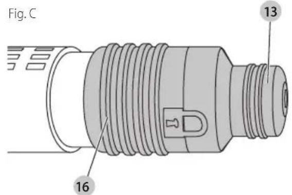
- Insert the bit shank into the tool holder 13 as far as it will go. The groove on the chisel shank 17 must be aligned with the symbol 15 on the toolholder. If
inserted correctly, the locking sleeve 16 moves back to the end position and shows a closed lock symbol.
- Pull on the bit to be sure that it is properly locked.
- If the chisel groove is not aligned with the symbol, or is not inserted to the complete depth the lock symbol remains open.
- To remove the bit, pull back the locking sleeve and pull the bit out.
text_image
Fig. C 13 16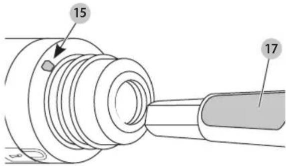
text_image
15 17Inserting and Removing SDS Max Accessories (Fig. D)
D25501, D25601, D25603, D25831
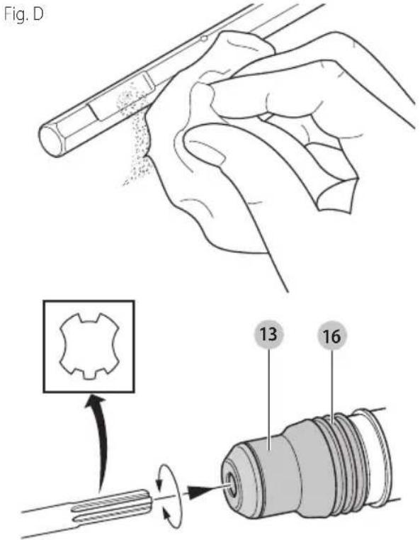
- Pull back the locking sleeve 16 and insert the bit shank. The bit shank must be clean.
- Turn the bit slightly until the sleeve snaps back into position.
- Ensure the bit is properly engaged. nOTE: The bit needs to move several centimeters in and out of the tool holder 13 when properly engaged.
- To remove the bit, pull back the locking sleeve and pull the bit out.
English
text_image
Fig. D 13 16Two-Stage Clutch/E-Clutch™ (Fig. E)
NOTICE: Always turn the tool off before changing torque control settings or damage to tool may result.
Two-stage clutch
D25603, D25651
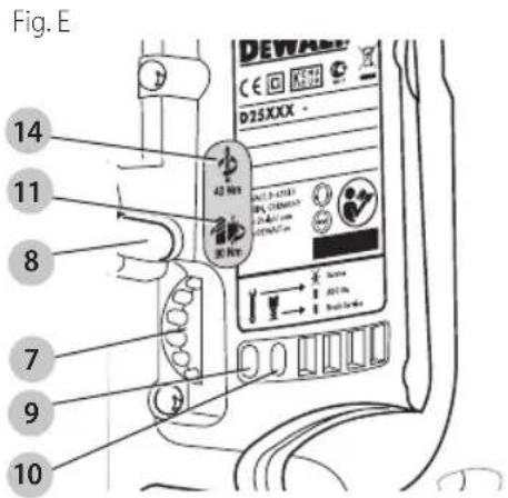
Clutch Setting 1 14 is designed for most hammerdrilling applications and is designed to easily clutch out when the drill bit encounters re-bar or other foreign substances. Clutch Setting 2 11 is designed for higher torque applications such as core-bits and deep hole hammerdrilling and is designed to clutch out at a higher torque threshold. Move the torque control lever 8 to Clutch Setting 1 or 2 as needed for application.
nOTE: Allow the motor housing to rotate a little while changing torque.
NOTE: If it is not possible to select Clutch Setting 2, run the unit under load and try again.
Each time the tool is plugged in, it will automatically default to Clutch Setting 1, the most sensitive setting.
E-CLUTCH™
D25603
In addition, E-Clutch™ offers increased user comfort and safety through an on-board antirotation technology capable of detecting if the user loses control of the hammer. When a jam is detected, the torque and speed are reduced instantly. The red indicator LED 9 illuminates when the E-Clutch™ is engaged.
text_image
Fig. E 14 11 8 7 9 10 DEWAB CE C N D25XXX - 42 MHz DC 3-6-100 DC 2-100000 DC 2-100000 DC 2-100000 DC 2-100000 DC 2-100000 DC 2-100000 DC 2-100000 DC 2-100000 DC 2-100000 DC 2-1000 DC 2-100 DC 2-100 DC 2-100 DC 2-100 DC 2-100 DC 2-100 DC 2-100 DC 2-100 DC 2-100 DC 2-100 DC 2-100 DC 2-100 DC 2-100 AC 3.5m AC 3.5m AC 3.5m AC 3.5m AC 3.5m AC 3.5m AC 3.5m AC 3.5m AC 3.5m AC 3.5m AC 3.5m AC 3.5m AC 3.5mElectronic Speed and Impact Control (Fig. E)
D25651, D25601, D25603, D25831, D25851
The electronic speed and impact control allows the use of smaller drill bits without the risk of bit breakage, hammerdrilling into light and brittle materials without shattering and optimal tool control for precise chipping. To set the control dial, turn the dial 7 to the desired level. The higher the number, the greater the speed and impact energy. Dial settings make the tool extremely adaptable for many different appli cations. The required setting depends on the bit size and hardness of material being drilled.
Mode Selector (Fig. A)
NOTICE: Never change the mode while the unit is running. Tool must come to a complete stop before activating the mode selector button or damage to the tool may result.
CAUTION: Do not change to hammerdrill mode with a bit in tool holder. Personal injury and damage to tool may result.
The D25501, D25553, D25601, D25603, and D25651 use two operating modes. To select the required operating mode, rotate the mode selector 6 until the arrow points to the hammerdrilling or the chipping icon. The D25831 and D25851 use only the chipping mode.
Hammerdrilling Mode ( ) T
D25501, D25553, D25601, D25603, D25651
The tool simultaneously rotates and impacts the work. This mode is appropriate for all concrete and masonry operations.
Chipping Mode (T)
D25831, D25851
The spindle lock is engaged during chipping mode so the tool impacts the work without rotating. This mode is appropriate for light chipping, chiseling and demolition applications.
nOTE: In chipping mode, the hammerdrill can also be used as a lever to free a jammed drill bit.
ENGLISH
Chisel Bit adjustment (0
D25831, D25851
Turn the mode selector to one of the chisel bit adjustment icons to adjust the chisel to the desired position. There are multiple positions to set the angle of the chisel. After finding the desired position, slightly maneuver the chisel bit back and forth to ensure the chisel is properly engaged.
Indicator Lights (Fig. A, E)
The yellow brush wear indicator LED 10 lights up when the carbon brushes are nearly worn out indicating that the tool needs servicing within the next 8 hours of use.
The red indicator LED 9 lights up if the lock-on slider 2 and/or E-Clutch™ is engaged in any mode except the chipping mode.
The red indicator LED 9 starts to flash if there is a fault with the tool or the brushes have completely worn out (refer to Repairs under Maintenance).
| INDICATOR DIAGNOSIS SOLUTION | |
| OFF Tool is functioning normally | Follow all warnings and instructions when operating tool |
| SOLID Perform and protect control has been activated | With tool properly supported, release trigger; the tool will function normally when the trigger is depressed again and the indicator light will go out |
| FLASHING Perform and protect control is malfunctioning | Take the tool to an authorized DEWALT repair agent. |
NOTE: If the tool power is insufficient for normal hammering and if the LED does not flash repeatedly after cycling the trigger, take the tool to an authorized DeWALT repair center.
OPERATION
WARNING: To reduce the risk of serious personal injury, turn unit off and disconnect it from power source before making any adjustments or removing/installing attachments or accessories.
An accidental start-up can cause injury.
WARNING: To reduce the risk of personal injury, ALWAYS ensure workpiece is anchored or clamped firmly. If hammerdrilling thin material, use a wood "back-up" block to prevent damage to the material.
WARNING: To reduce the risk of personal injury, ALWAYS operate the tool with the side handle properly installed and securely tightened. Failure to do so may result in the side handle slipping during
tool operation and subsequent loss of control. Hold tool with both hands to maximize control.
WARNING: Drill may stall if overloaded causing a sudden twist. Always expect the stall. Grip the drill firmly with both hands to control the twisting action and avoid injury.
Proper Hand Position (Fig. F)
WARNING: To reduce the risk of serious personal injury, A. 1.5 YS use proper hand position as shown.
WARNING: To reduce the risk of serious personal injury, ALWAYS hold securely in anticipation of a sudden reaction.
Proper hand position requires one hand on the side handle 3, with the other hand on the main handle 4.
text_image
Fig. F 3 4 3 4NOTE: Operating temperature of this tool is 19^ F to 104^ F ( -7^ C to +40^ C). Using the tool outside of this temperature range will decrease the life of the tool.
Trigger Switch (Fig. A)
D25501, D25553, D25601, D25603, D25651
To turn the tool on, depress the trigger switch 1. To stop the tool, release the trigger switch.
In chipping mode only, lock the trigger switch on by pushing the lock-on slider 2 upward while depressing the trigger switch.
To deactivate the lock-on slider, depress the trigger switch once then release.
The lock-on slider may only be activated in chipping mode. The machine will stop running when trying to engage the lock-on slider in hammerdrilling mode. The motor will stop
English
if the lock-on slider is activated when changing from chisel mode into hammerdrilling mode.
D25831, D25851
For continuous operation, move the toggle switch 1 to the on position. To stop continuous operation, move the toggle switch to the off position.
Soft Start Feature
The soft start feature allows you to build up speed slowly, thus preventing the drill bit from walking off the intended hole position when starting. The soft start feature also reduces the immediate torque reaction transmitted to the gearing and the operator if the hammer is started with the drill bit in an existing hole.
Hammerdrilling with a Solid Bit (Fig. A, E) D25501, D25553, D25601, D25603, D25651
nOTE: The D25831 and D25851 have only chipping modes with no hammerdrilling capability.
- Set the mode selector 6 to hammerdrilling mode.
- For D25603 and D25651 only, move the torque control lever 8 to Setting 1 14.
- Set the speed and impact control dial 7.
- Insert the appropriate drill bit.
- Adjust the side handle (front or rear position) 3.
- Mark the spot where the hole is to be drilled.
- Place the drill bit on that mark and depress the trigger switch 1.
- Apply only enough pressure to engage active vibration control (refer to SHOCKS Active Vibration Control® System).
- To stop the tool, release the trigger switch. Always turn the tool off when work is finished and before unplugging.
Hammerdrilling with a Core Bit (Fig. A, E) D25501, D25553, D25601, D25603, D25651
CAUTION: Do not use a core bit for hammerdrilling wood. Personal injury and damage to tool may result.
NOTE: The D25831, D25851 have only chipping modes with no hammerdrilling capability.
- Set the mode selector 6 to hammerdrilling mode.
- For D25603 and D25651 only, move the torque control lever 8 to Setting 2 11.
- Turn the speed and impact control dial 7 to the desired speed.
- Adjust the side handle (front or rear position) 3.
- Assemble the centering bit and adapter shank into core bit.
- Mark the spot where the hole is to be drilled.
- Place the centering bit on that mark and depress the trigger switch 1. nOTE: Some core drills require the removal of centering
bit after about 1 cm of penetration. If so, remove and continue hammerdrilling.
- When hammerdrilling through a structure thicker than the depth of the core bit, break away the round cylinder of concrete or core inside the bit at regular intervals. To avoid unwanted breaking away of concrete around the hole, first drill a hole the diameter of the centering bit completely through the structure. Then drill the cored hole halfway from each side of the structure.
- To stop the tool, release the trigger switch. Always turn the tool off when work is finished and before unplugging.
Chipping and Chiseling (Fig. A)
D25831, D25851
- Set the mode selector 6 to chipping mode.
- Set the impact control dial 7 to desired setting (refer to Electronic Speed and Impact Control).
- Insert the appropriate chisel and rotate it by hand to lock it into the desired position. nOTE: For SDS Max models, only use SDS Max bits.
- Adjust the side handle (front or rear position) 3.
- Depress the trigger switch 1.
- Apply only enough pressure to engage active vibration control (refer to SHOCKS Active Vibration Control® System).
- To stop the tool, release the trigger switch. Always turn the tool off when work is finished and before unplugging.
MAINTENANCE
WARNING: To reduce the risk of serious personal injury, turn unit off and disconnect it from power source before making any adjustments or removing/installing attachments or accessories. An accidental start-up can cause injury.
Cleaning
WARNING: Blow dirt and dust out of all air vents with clean, dry air at least once a week. To minimize the risk of eye injury, always wear ANSI Z87.1 approved eye protection when performing this.
WARNING: Never use solvents or other harsh chemicals for cleaning the non-metallic parts of the tool. These chemicals may weaken the plastic materials used in these parts. Use a cloth dampened only with water and mild soap. Never let any liquid get inside the tool; never immerse any part of the tool into a liquid.
Lubrication
Your tool was properly lubricated before leaving the factory. In from two to six months, depending upon use, take or send your tool to an authorized service center for a complete cleaning, inspection and lubrication. Tools used constantly on production jobs will need relubrication more often. Also, tools "out of service" for long periods should be relubricated before being put back to work.
Accessories
WARNING: Since accessories, other than those offered by DeWALT, have not been tested with this product, use of such accessories with this tool could be hazardous. To reduce the risk of injury, only DeWALT recommended accessories should be used with this product.
Recommended accessories for use with your tool are available at extra cost from your local dealer or authorized service center. If you need assistance in locating any accessory, please contact DrWALT Industrial Tool Co., 701 East Joppa Road, Towson, MD 21286, call 1-800-4-DeWALT (1-800-433-9258) or visit our website: www.dewalt.com.
| MAXIMUM CAPACITY | ||||
| D25501D25553 | D2560D25603 | D25651 D25831 D25851 | ||
| Concrete 1-9/16"(40 mm) | 1-3/4"(45 mm) | 1-3/4"(45 mm) | — | |
| RPM 490 415 415 — — | ||||
| No loadBPM | 3300 2840 2840 | 1430–2840 | 1430–2840 | |
Repairs
WARNING: To assure product SAFETY and HELIBILITIES, repairs, maintenance and adjustment (including brush inspection and replacement, when applicable) should be performed by a DeWALT factory service center or a DeWALT authorized service center. Always use identical replacement parts.
Register Online
Thank you for your purchase. Register your product now for:
- WARRAnTY sERViCE: Registering your product will help you obtain more efficient warranty service in case there is a problem with your product.
- COnFiRMATiOn OF OWnERshiP: In case of an insurance loss, such as fire, flood or theft, your registration of ownership will serve as your proof of purchase.
• FOR YOUR SAFETY: Registering your product will allow us to contact you in the unlikely event a safety notification is required under the Federal Consumer Safety Act.
Register online at www.dewalt.com/register.
Three Year Limited Warranty
DeWALT will repair, without charge, any defects due to faulty materials or workmanship for three years from the date of purchase. This warranty does not cover part failure due to normal wear or tool abuse. For further detail of warranty coverage and warranty repair information, visit www.dewalt.com or call 1-800-4-DeWALT (1-800-433-9258). This warranty does not apply to accessories or damage caused where repairs have been made or attempted by others. This warranty gives you specific legal rights and you may have other rights which vary in certain states or provinces.
In addition to the warranty, DEWALT tools are covered by our:
1 YEAR FREE sSERVICE
DeWALT will maintain the tool and replace worn parts caused by normal use, for free, any time during the first year after purchase.
90 DAY MOnEY BACK gUARAnTEE
If you are not completely satisfied with the performance of your DeWALT Power Tool, Laser, or Nailer for any reason, you can return it within 90 days from the date of purchase with a receipt for a full refund – no questions asked.
IATin AMERiCA: This warranty does not apply to products sold in Latin America. For products sold in Latin America, see country specific warranty information contained in the packaging, call the local company or see website for warranty information.
FREE WARning IABEI REPIACEMENT: If your warning labels become illegible or are missing, call 1-800-4-DrWALT (1-800-433-9258) for a free replacement.
text_image
Technical diagram of a DFWALT drill with numbered parts and an inset view showing the control panel.D25651, D25601, D25603, D25831, D25851
text_image
14 11 8 7 9 10 DEWAN CE 10 D25XXX - 40 Nm A2.1-0.0135 Mn 1.016mm 0.0135mm 0.0135mm 0.0135mm X links X links X links X linksD25651, D25601, D25603, D25831, D25851
Mode martelage-perforage ( )T D25501, D25553, D25601, D25603, D25651
D25651, D25601, D25603, D25831, D25851
natural_image
Line drawing of a hand holding a pen or tool, no text or symbols present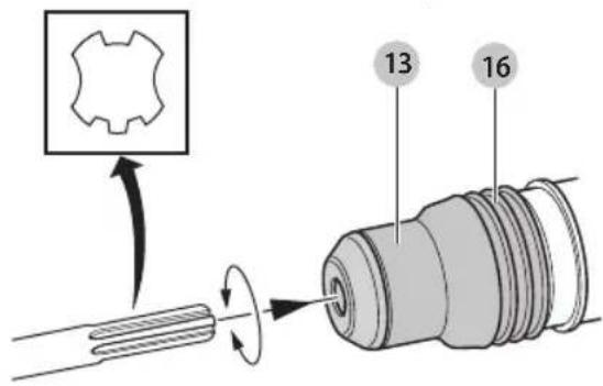
text_image
Technical diagram showing a gear component being inserted into a threaded connector, with numbered parts 13 and 16 indicated.Embrague de dos etapas/E-Clutch™ (Fig. E)
D25651, D25601, D25603, D25831, D25851
Eje Central Lázaro Cárdenas No. 18 - Local (55) 5588 9377 D, Col. Obrera
MERIDA, YUC
Calle 63 #459-A - Col. Centro (999) 928 5038
MONTERREY, N.L.
Av. Francisco I. Madero 831 Poniente - Col. (818) 375 23 13 Centro
PUEBLA, PUE
17 Norte #205 - Col. Centro (222) 246 3714
QUERETARO, QRO
Av. San Roque 274 - Col. San Gregorio (442) 2 17 63 14
SAN LUIS POTOSI, SLP
DEWALT Industrial Tool Co., 701 East Joppa Road, Towson, MD 21286
(MAR17) Part No. N487907 D25501, D25553, D25601, D25603, D25651, D25831, D25851
Copyright © 2010, 2017 DEWALT
The following are trademarks for one or more D _L WALT power tools: the yellow and black color scheme, the "D" shaped air intake grill, the array of pyramids on the handgrip, the kit box configuration, and the array of lozenge-shaped humps on the surface of the tool.