
RAMPAGE IV BLACK EDITION - Motherboard ASUS - Free user manual and instructions
Find the device manual for free RAMPAGE IV BLACK EDITION ASUS in PDF.
| Product Type | ATX Motherboard |
| Dimensions | 30.5 cm x 27.2 cm (Extended ATX form factor) |
| Processor Socket | LGA2011 for Intel Core i7 processors |
| Chipset | Intel X79 Express |
| Supported Memory | 8 x DDR3, max 64 GB, frequency up to 2800 MHz (O.C.) |
| Expansion Slots | 4 x PCIe 3.0 x16, 2 x PCIe 2.0 x1 |
| Multi-GPU Technologies | NVIDIA SLI (4-Way) and AMD CrossFireX |
| SATA Storage | 6 x SATA 6 Gb/s (ASMedia + Intel) + 4 x SATA 3 Gb/s (Intel) |
| USB | 8 x USB 3.0 (6 on rear panel) + 10 x USB 2.0 |
| Audio | ROG SupremeFX Black 7.1-channel, Cirrus Logic CS4398 DAC, 600-ohm headphone amplifier |
| Networking | Gigabit Intel + Wi-Fi 802.11 a/b/g/n/ac + Bluetooth 4.0 |
| Power Requirement | 24-pin + 8-pin + 4-pin ATX connectors, 1000W recommended for multi-GPU configurations |
| Key Features | OC Panel, Sonic Radar, GameFirst II, MemOK!, USB BIOS Flashback, AI Suite 3 |
| Maintenance and Cleaning | Disconnect power, use a dry antistatic cloth, avoid moisture |
| Safety | Electrostatic discharge, disconnect before intervention, use on stable surface |
| Spare Parts and Repairability | ASUS warranty, repair by authorized professional, parts available on ASUS website |
| General Information | Included manual, support DVD, SATA cables, I/O shield, Wi-Fi antenna, OC Panel |
Frequently Asked Questions - RAMPAGE IV BLACK EDITION ASUS
User questions about RAMPAGE IV BLACK EDITION ASUS
0 question about this device. Answer the ones you know or ask your own.
Ask a new question about this device
Download the instructions for your Motherboard in PDF format for free! Find your manual RAMPAGE IV BLACK EDITION - ASUS and take your electronic device back in hand. On this page are published all the documents necessary for the use of your device. RAMPAGE IV BLACK EDITION by ASUS.
USER MANUAL RAMPAGE IV BLACK EDITION ASUS
RAMPAGE IV BLACK EDITION

F8336
Première édition
Juillet 2013
Offer to Provide Source Code of Certain Software
This product may contain copyrighted software that is licensed under the General Public License ("GPL") and under the Lesser General Public License Version ("LGPL"). The GPL and LGPL licensed code in this product is distributed without any warranty. Copies of these licenses are included in this product.
You may obtain the complete corresponding source code (as defined in the GPL) for the GPL Software, and/or the complete corresponding source code of the LGPL Software (with the complete machine-readable "work that uses the Library") for a period of three years after our last shipment of the product including the GPL Software and/or LGPL Software, which will be no earlier than December 1, 2011, either
(1) for free by downloading it from http://support.asus.com/download;
or
(2) for the cost of reproduction and shipment, which is dependent on the preferred carrier and the location where you want to have it shipped to, by sending a request to:
ASUSTeK Computer Inc.
Legal Compliance Dept.
15 Li Te Rd.,
Beitou, Taipei 112
Taiwan
In your request please provide the name, model number and version, as stated in the About Box of the product for which you wish to obtain the corresponding source code and your contact details so that we can coordinate the terms and cost of shipment with you.
The source code will be distributed WITHOUT ANY WARRANTY and licensed under the same license as the corresponding binary/object code.
This offer is valid to anyone in receipt of this information.
ASUSTeK is eager to duly provide complete source code as required under various Free Open Source Software licenses. If however you encounter any problems in obtaining the full corresponding source code we would be much obliged if you give us a notification to the email address gpl@asus.com, stating the product and describing the problem (please do NOT send large attachments such as source code archives etc to this email address).
Table des matieres
3.5 Menu Main (Principal) 3-22
3.6 Menu Advanced (Avancé) 3-24
3.6.1 CPU Configuration (Configuration du CPU) 3-25
3.6.2 System Agent Configuration (Configuration d'agent système) 3-27
3.6.3 PCH Configuration (Configuration PCH) 3-27
3.6.4 SATA Configuration (Configuration SATA) 3-28
3.6.5 USB Configuration (Configuration USB) 3-30
3.6.6 Onboard Devices Configuration (Configuration des péripériques embarqués) 3-31
3.6.7 APM (Gestion d'alimentation avancée) 3-33
3.6.8 Network Stack (Pile réseau) 3-34
3.6.9 ROG Effects (Effets ROG) 3-34
3.7 Menu Monitor (Surveillance) 3-35
4.6 ROG Connect 4-44
4.7 MemTweaklt 4-46
4.8 ROG RAMDisk 4-48
4.9 Sonic Radar 4-51
4.10 GameFirst II 4-56
- Sonic Radar
- DTS Connect
ROG Extreme Engine Digi+ III
Extreme Engine Digi+ III
Loadline Calibration
Configurations mémoire
VoussoupiezinstallerdesmodulesmémoireDDR3nontaponnéset nonECCde2Go,4Go et8Go surles interfaces de connexion DDR3.

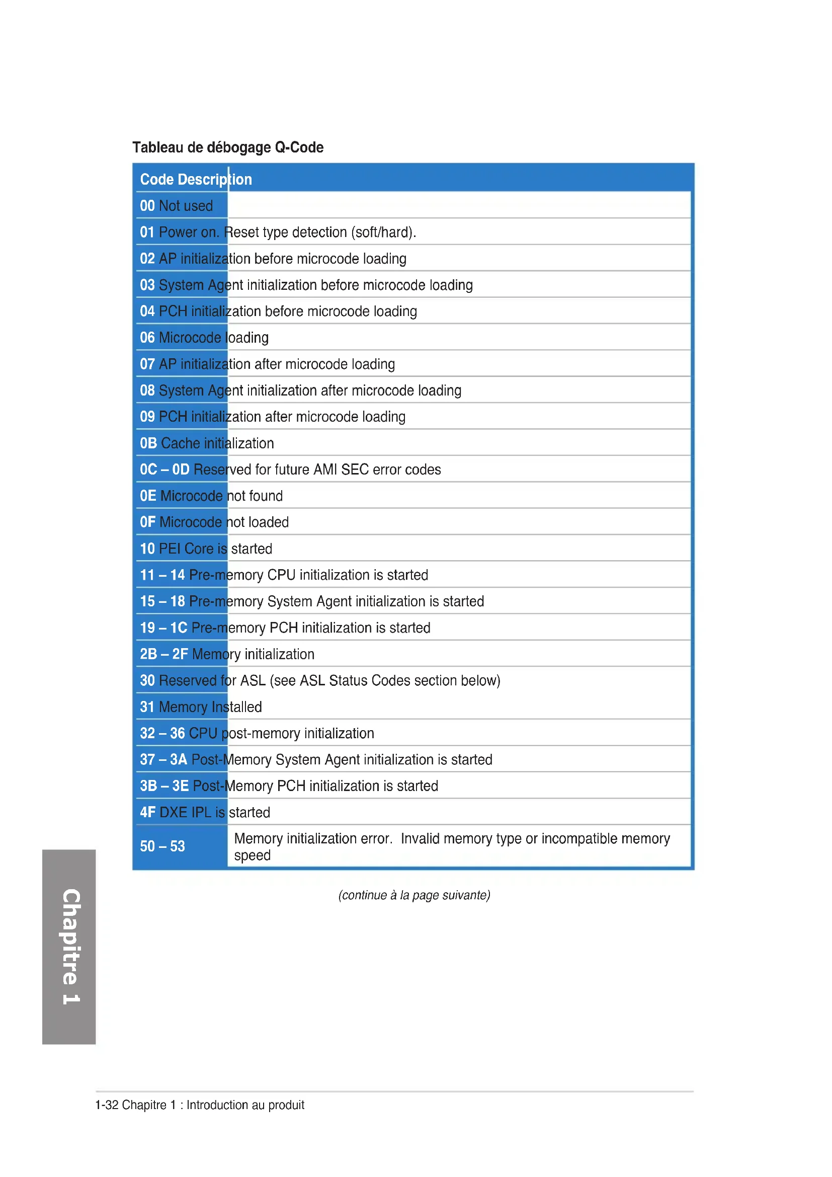
| Code Description | |
| 00 Not used | |
| 01 Power on. Reset type detection (soft/hard). | |
| 02 AP initialization before microcode loading | |
| 03 System Agent initialization before microcode loading | |
| 04 PCH initialization before microcode loading | |
| 06 Microcode loading | |
| 07 AP initialization after microcode loading | |
| 08 System Agent initialization after microcode loading | |
| 09 PCH initialization after microcode loading | |
| 0B Cache initialization | |
| 0C - 0D Reserved for future AMI SEC error codes | |
| 0E Microcode not found | |
| 0F Microcode not loaded | |
| 10 PEI Core is started | |
| 11 - 14 Pre-memory CPU initialization is started | |
| 15 - 18 Pre-memory System Agent initialization is started | |
| 19 - 1C Pre-memory PCH initialization is started | |
| 2B - 2F Memory initialization | |
| 30 Reserved for ASL (see ASL Status Codes section below) | |
| 31 Memory Installed | |
| 32 - 36 CPU post-memory initialization | |
| 37 - 3A Post-Memory System Agent initialization is started | |
| 3B - 3E Post-Memory PCH initialization is started | |
| 4F DXE IPL is started | |
| 50 - 53 | Memory initialization error. Invalid memory type or incompatible memory speed |
| Code Description |
| 54 Unspecified memory initialization error |
| 55 Memory not installed |
| 56 Invalid CPU type or Speed |
| 57 CPU mismatch |
| 58 CPU self test failed or possible CPU cache error |
| 59 CPU micro-code is not found or micro-code update is failed |
| 5A Internal CPU error |
| 5B Reset PPI is not available |
| 5C - 5F Reserved for future AMI error codes |
| E0 S3 Resume is stared (S3 Resume PPI is called by the DXE IPL) |
| E1 S3 Boot Script execution |
| E2 Video repost |
| E3 OS S3 wake vector call |
| E4 - E7 Reserved for future AMI progress codes |
| E8 S3 Resume Failed |
| E9 S3 Resume PPI not Found |
| EA S3 Resume Boot Script Error |
| EB S3 OS Wake Error |
| EC - EF Reserved for future AMI error codes |
| F0 Recovery condition triggered by firmware (Auto recovery) |
| F1 Recovery condition triggered by user (Forced recovery) |
| F2 Recovery process started |
| F3 Recovery firmware image is found |
| F4 Recovery firmware image is loaded |
| F5 - F7 Reserved for future AMI progress codes |
| F8 Recovery PPI is not available |
| Code Description |
| F9 Recovery capsule is not found |
| FA Invalid recovery capsule |
| FB - FF Reserved for future AMI error codes |
| 60 DXE Core is started |
| 61 NVRAM initialization |
| 62 Installation of the PCH Runtime Services |
| 63 - 67 CPU DXE initialization is started |
| 68 PCI host bridge initialization |
| 69 System Agent DXE initialization is started |
| 6A System Agent DXE SMM initialization is started |
| 6B - 6F System Agent DXE initialization (System Agent module specific) |
| 70 PCH DXE initialization is started |
| 71 PCH DXE SMM initialization is started |
| 72 PCH devices initialization |
| 73 - 77 PCH DXE Initialization (PCH module specific) |
| 78 ACPI module initialization |
| 79 CSM initialization |
| 7A - 7F Reserved for future AMI DXE codes |
| 90 Boot Device Selection (BDS) phase is started |
| 91 Driver connecting is started |
| 92 PCI Bus initialization is started |
| 93 PCI Bus Hot Plug Controller Initialization |
| 94 PCI Bus Enumeration |
| 95 PCI Bus Request Resources |
| 96 PCI Bus Assign Resources |
| 97 Console Output devices connect |
| 98 Console input devices connect |
| 99 Super IO Initialization |
| 9A USB initialization is started |
| 9B USB Reset |
| Code Description |
| 9C USB Detect |
| 9D USB Enable |
| 9E-9F Reserved for future AMI codes |
| A0 IDE initialization is started |
| A1 IDE Reset |
| A2 IDE Detect |
| A3 IDE Enable |
| A4 SCSI initialization is started |
| A5 SCSI Reset |
| A6 SCSI Detect |
| A7 SCSI Enable |
| A8 Setup Verifying Password |
| A9 Start of Setup |
| AA Reserved for ASL (see ASL Status Codes section below) |
| AB Setup Input Wait |
| AC Reserved for ASL (see ASL Status Codes section below) |
| AD Ready To Boot event |
| AE Legacy Boot event |
| AF Exit Boot Services event |
| B0 Runtime Set Virtual Address MAP Begin |
| B1 Runtime Set Virtual Address MAP End |
| B2 Legacy Option ROM Initialization |
| B3 System Reset |
| B4 USB hot plug |
| B5 PCI bus hot plug |
| B6 Clean-up of NVRAM |
| B7 Configuration Reset (reset of NVRAM settings) |
| B8-BF Reserved for future AMI codes |
| D0 CPU initialization error |
| D1 System Agent initialization error |
| D2 PCH initialization error |
| D3 Some of the Architectural Protocols are not available |
| D4 PCI resource allocation error. Out of Resources |
| D5 No Space for Legacy Option ROM |
| D6 No Console Output Devices are found |
| D7 No Console Input Devices are found |
| D8 Invalid password |
| D9 Error loading Boot Option (LoadImage returned error) |
| DA Boot Option is failed (StartImage returned error) |
| DB Flash update is failed |
| DC Reset protocol is not available |
Points de reference ACPI/ASL
| Code Description |
| 0x01 System is entering S1 sleep state |
| 0x02 System is entering S2 sleep state |
| 0x03 System is entering S3 sleep state |
| 0x04 System is entering S4 sleep state |
| 0x05 System is entering S5 sleep state |
| 0x10 System is waking up from the S1 sleep state |
| 0x20 System is waking up from the S2 sleep state |
| 0x30 System is waking up from the S3 sleep state |
| 0x40 System is waking up from the S4 sleep state |
| 0xAC System has transitioned into ACPI mode. Interrupt controller is in PIC mode. |
| 0xAA System has transitioned into ACPI mode. Interrupt controller is in APIC mode. |
1.2.8 Jumper
(4-pin CPU_FAN; 4-pin CPU_OPT; 4-pin CHA_FAN1/ CHA_FAN2/ CHA_FAN3; 4-pin OPT_FAN1/OPT_FAN2/OPT_FAN3)
(24-pin EATXPWR; 4-pin EATX12V_1; 4-pin EZ_PLUG; 8-pin EATX12V_2)
Load Air-cooled Gamer's OC Profile/ Load Water-cooled Gamer's OC Profile Load 160BCLK OC Profile/ Load 170BCLK OC Profile/ Load 180BCLK OC Profile/ Load 190BCLK OC Profile
CPU Core Ratio (Ratio CPU) [Auto]
[Mode 2] Overclocking et performances.
DRAM CAS# Latency [Auto]
Options de configuration : [Auto] [1] - [31]
DRAM RAS# to CAS# Delay [Auto]
Options de configuration : [Auto] [1] - [31]
DRAM RAS# PRE Time [Auto]
Options de configuration : [Auto] [1] - [31]
DRAM RAS# ACT Time [Auto]
Options de configuration : [Auto] [1] - [63]
DRAM COMMAND Rate [Auto]
Options de configuration : [Auto] [1] - [3]
Latency Boundary A [Auto]
Options de configuration : [Auto] [1] - [27]
Latency Boundary B [Auto]
Options de configuration : [Auto] [1] - [14]
Latency Compensator [Auto]
Options de configuration : [Auto] [Enabled] - [Disabled]
Secondary Timings
DRAM RAS# to RAS# Delay [Auto]
Options de configuration : [Auto] [1] - [15]
DRAM REF Cycle Time [Auto]
Options de configuration : [Auto] [1] - [511]
DRAM Refresh Interval [Auto]
Options de configuration : [Auto] [1] - [32767]
DRAM WRITE Recovery Time [Auto]
Options de configuration : [Auto] [1] - [16]
DRAM READ to PRE Time [Auto]
Options de configuration : [Auto] [1] - [15]
DRAM FOUR ACT WIN Time [Auto]
Options de configuration : [Auto] [1] - [255]
DRAM WRITE to READ Delay [Auto]
Options de configuration : [Auto] [1] - [15]
DRAM CKE Minimum pulse width [Auto]
Options de configuration : [Auto] [1] - [15]
DRAM CAS# Write to Latency [Auto]
Options de configuration : [Auto] [1] - [31]
Third Timings
tRDRD [Auto]
Options de configuration : [Auto] [0 DRAM Clock] - [7 DRAM Clock]
tRRDD [Auto]
Options de configuration : [Auto] [0 DRAM Clock] - [7 DRAM Clock]
tWWDR [Auto]
Options de configuration : [Auto] [0 DRAM Clock] - [7 DRAM Clock]
tWWDD [Auto]
Options de configuration : [Auto] [0 DRAM Clock] - [7 DRAM Clock]
tRWDR [Auto]
Options de configuration : [Auto] [0 DRAM Clock] - [15 DRAM Clock]
tRWDD [Auto]
Options de configuration : [Auto] [0 DRAM Clock] - [15 DRAM Clock]
tWRDR [Auto]
Options de configuration : [Auto] [0 DRAM Clock] - [7 DRAM Clock]
tWRDD [Auto]
Options de configuration : [Auto] [0 DRAM Clock] - [7 DRAM Clock]
tRWSR [Auto]
Options de configuration : [Auto] [0 DRAM Clock] - [15 DRAM Clock]
tCCD [Auto]
Options de configuration : [Auto] [0 DRAM Clock] - [7 DRAM Clock]
tCCDWR [Auto]
Options de configuration : [Auto] [0 DRAM Clock] - [7 DRAM Clock]
Latency Timings
DRAM RTL (CHA/CHB/CHC/CHD D0/D1 R0/R1) [Auto]
Options de configuration : [Auto] [Advance 2/4/6/8/10/12/14 Clock] [Normal]
[Delay 2/4/6/8/10/12/14 Clock]
DRAM IOL (CHA/CHB/CHC/CHD D0/D1 R0/R1) [Auto]
Options de configuration : [Auto] [Advance 1 - 14 Clock] [Normal] [Delay 1 - 14 Clock]
Misc
DRAM CLK Period [Auto]
Options de configuration : [Auto] [1] - [10]
DRAM Alignment [Optimized]
Options de configuration : [Optimized] [Standard]
DRAM Training [Auto]
Options de configuration : [Auto] [Ignore] [Enabled]
Enhanced Training (CHA/CHB/CHC/CHD) [Auto]
Options de configuration : [Auto] [Disabled] [Enabled]
Receiver Slew [Auto]
Options de configuration : [Auto] [Normal] [More]
Transmitter Slew [Auto]
Options de configuration : [Auto] [Normal] [More]
MCH Recheck [Auto]
Options de configuration : [Auto] [Disabled] [Enabled]
MRC Fast Warm Boot [Auto]
Options de configuration : [Auto] [Disabled]
DRAM Swizzling Bit 0 / Bit 1 [Auto]
Options de configuration : [Auto] [Disabled] [Enabled]
RAW MHz Aid [Auto]
Options de configuration : [Auto] [Disabled] [Enabled]
DIGl+ Power Control

CPU Power Duty Control [T.Probe]
VCCSA Fixed Frequency (Fréquence VCCSA fixe) [XXX]
Long Duration Maintained [Auto]
Short Duration Power Limit [Auto]
Additional Turbo Voltage [Auto]
CPU Core Current Limit [Auto]
2nd VTTCPU Voltage (Second voltage VTT du CPU) [Auto]
CPU VCCSA Voltage (Voltage VCCSA) [Manual Mode]
Eventual PLL Termination Voltage
CPU PLL Termination [Auto]
BCLK Recovery (Réçupération BCLK) [Enabled]
Options de configuration : [Disabled] [Enabled]
CPU Tweakers' Paradise
DRAM CTRL REF Voltage on (CHA) / (CHB) / (CHC) / (CHD) [Auto]
DRAM DATA REF Voltage on (CHA) / (CHB) / (CHC) / (CHD) [Auto]
DRAM Read REF Voltage (CHA) / (CHB) / (CHC) / (CHD) [Auto]
3.5 Menu Main (Principal)
Intel Adaptive Thermal Monitor
Hyper-threading [Enabled]
Intel(R) Virtualization Technology
SATA Mode (Mode SATA) [AHCI]
Determine le mode de configuration SATA.
Legacy USB Support (Support USB hériè) [Enabled]
Asmedia USB 3.0 Battery Charging Support
Ipv4 PXE Support [Enable]
Options de configuration : [Disabled] [Enabled]
Ipv6 PXE Support [Enable]
Options de configuration : [Disabled] [Enabled]

Anti Surge Support (Support anti-surtensions) [Enabled]
CPU Voltage; 3.3V Voltage; 5V Voltage; 12V Voltage; VTT CPU Voltage;
CPU VCCSA Voltage; CPU PLL Voltage; DRAM AB Voltage; DRAM CD Voltage;
PCH 1.1 Voltage; PCH 1.5 Voltage; 2nd VTTCPU Voltage
CPU Temperature; MB Temperature; PCH Temperature; PCH Overheat Protection; OPT1/OPT2/OPT3 Temperature; OPT TEMP1/TEMP2/TEMP3 [xxxxoC/ xxxoF]
CPU FAN Speed; CPU OPT Speed; Chassis FAN 1/FAN 2/FAN 3 Speed; Opt FAN 1/FAN 2/FAN 3 Speed [xxxxRPM] or [Ignored] / [N/A]
CPU Fan Speed Low Limit
CPU Fan Max. Duty Cycle
CPU Fan Min. Duty Cycle
OPTFAN 1/2/3 Low Speed Temp [25°C]
SATA Support (Support SATA) [All Devices]
USB Support (Support USB) [Partial Initialization]
Next boot after AC Power Loss
DirectKey [Go to BIOS Setup]
CSM (Compatibility Support Module)
Launch CSM (Executer CSM) [Auto]
Boot from Network Devices [Legacy OpRom first]
Options de configuration : [Legacy OpROM first] [UEFI driver first] [Ignore]
Boot from Storage Devices [Legacy OpRom first]
Options de configuration : [Both, Legacy OpROM first] [Both, UEFI first] [Legacy
OpROM first] [UEFI driver first] [Ignore]
Boot from PCIe/PCI Expansion Devices [Legacy OpRom first]
Options de configuration : [Legacy OpROM first] [UEFI driver first]
BCLK Frequency (Frequence BCLK) [Auto]
Load from profile (Charger un profil)
Launch EFI Shell from filesystem device (Lancer l'application EFI Shell)
TurboV Processing Unit (TPU)
Energy Processing Unit (EPU)
Wi-Fi GO! & NFC Remote
Interface Wi-Fi GO! & NFC Remote
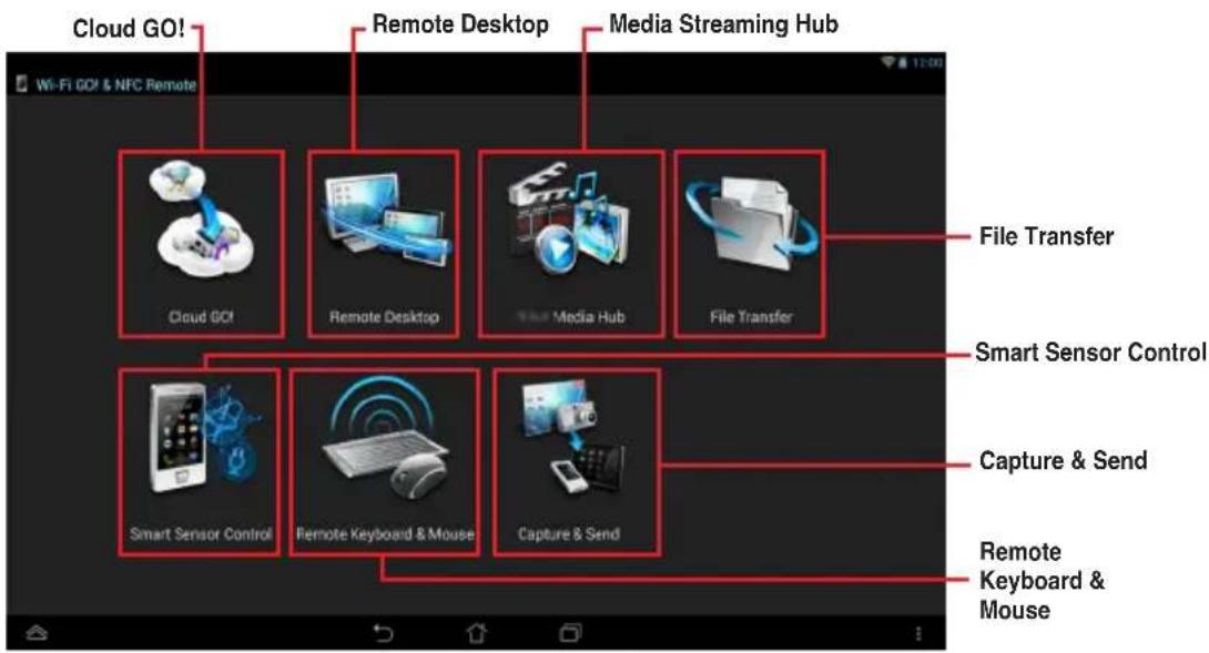

Remote Keyboard & Mouse
Lancer USB 3.0 Boost
WARNING: ALL DATA ON SELECTED DISKS WILL BE LOST. Are you sure you want to create this volume? (Y/N):
DECLARATION OF CONFORMITY

Responsible Party Name: Asus Computer International
Address: 800 Corporate Way, Fremont, CA 94539.
Phone/Fax No: (510)739-3777/(510)608-4555
hereby declares that the product
Product Name : Motherboard OC accessory
Model Number:OC Panel
Conforms to the following specifications:
FCC Part 15, Subpart B, Unintentional Radiators
Supplementary Information:
This device complies with part 15 of the FCC Rules. Operation is subject to the following two conditions: (1) This device may not cause harmful interference, and (2) this device must accept any interference received, including interference that may cause undesired operation.
Representative Person's Name: Steve Chang / President

Date: Apr. 16, 2013

Declaration Date: 16/04/2013
Year to begin affixing CE marking: 2013
Declaration Date: 16/04/2013
Year to begin affixing CE marking:2013

EC Declaration of Conformity
We, the undersigned.
| Manufacturer: | ASUSTEK COMPUTER INC. |
| Address, City: | 4F, No. 150, LI-TE Rd., PETOU, TIAPEI 112, TAIWAN |
| Country: | TAIWIAN |
| Authorized representative in Europe: | ASUS COMPUTER GmbH |
| Address, City: | HARKORT STR. 21-23, 40880 RATINCEN |
| Country: | GERMANY |
| declare the following apparatus: | |
| Product name : | Motherboard OC accessory |
| Model name : | OC Panel |
conform with the essential requirements of the following directives:
2004/108/EC-EMC Directive EN 59892-2010
EN 61000-3:2006+A2:2009
declare the following apparatus:
Product name :
| Model name : | OC Panel |
EN55022:2010 EN 61839.2-2020E:12-2020
| EN 55013:2007+A1:2008+A2:2006 | EN 55020:2007+A11:2011 |
1999/5/EC-R &TTE Directive 1999/5/EC-2008/14/3686/10
| EN 300-328 V1.7.1(2006-10) | EN 301-489-1 V1.8.2(2011-09) |
| EN 300 440-1 V1.6.1(2010-08) | EN 301 489-3 V1.4.1(2002-08) |
| EN 300 440-2 V1.4.1(2010-08) | EN 301 489-4 V1.4.1(2009-05) |
| EN 301 511 V9.0.2(2003-03) | EN 301 489-7 V1.3.1(2005-11) |
| EN 301 908-1 V5.2.1(2011-05) | EN 301 489-9 V1.4.1(2007-11) |
| EN 301 908-2 V5.2.1(2011-07) | EN 301 489-17 V2.1 (2009-05) |
EN301893V1.6.1(2011-11) EN302544V1.1.1(2009-01) EN302623V1.1.1(2009-01) EN50360:2001
EN 62479:2010 EN 50385:2002
| EN 60950.1 / A12:2011 | EN 60065.2002 / A12:2011 |
2009/125/EC-ErP Directive
| □ Regulation (EC) No. 1275/2008 □ Regulation (EC) No. 642/2009 | □ Regulation (EC) No. 278/2009 |
2011/65/EU-RoHS Directive Vol. 13208
CE marking
(EC conformity marking)
Position: CEO
Name: Jerry Shen
m : x = 1 或 3x + 4y + 1 = 0

Signature :
Ver. 120601
Signature :
Date :
m - 1 0 ;