
RM-BR300 - Remote control SONY - Free user manual and instructions
Find the device manual for free RM-BR300 SONY in PDF.
| Product Type | Remote control (three-axis joystick controller for cameras) |
| Brand | Sony |
| Model | RM-BR300 |
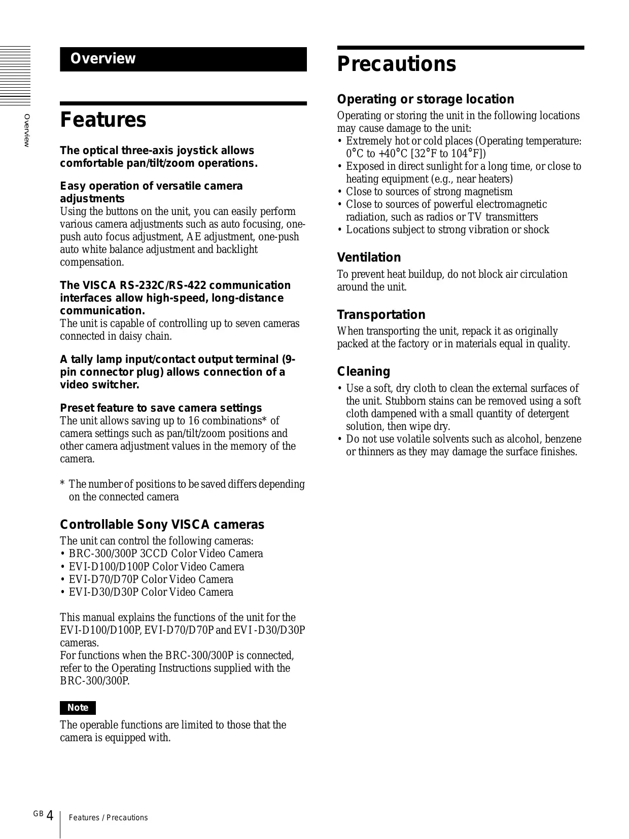
| Dimensions (W × H × D) | 391.3 × 185 × 145.9 mm (without protruding parts) |
| Weight | Approx. 950 g |
| Power Supply | 12 V DC (10.8 to 13.2 V DC) via supplied AC adapter |
| Power Consumption | 0.2 A max. (2.4 W) |
| Operating Temperature | 0 °C to +40 °C |
| Storage Temperature | -20 °C to +60 °C |
| Main Functions | Pan/tilt/zoom control, memory for up to 16 positions, camera settings (focus, white balance, backlight compensation), VISCA RS-232C/RS-422 interface, control up to 7 cameras in daisy chain |
| Compatible Cameras | Sony BRC-300/300P, EVI-D100/D100P, EVI-D70/D70P, EVI-D30/D30P |
| Connectors | VISCA RS-232C (mini-DIN 8-pin), VISCA RS-422 (9-pin), TALLY/CONTACT (9-pin), DC IN 12V (JEITA type 4) |
| Communication | RS-232C or RS-422, baud rates 9,600 or 38,400 bps |
| Supplied Accessories | AC adapter, power cord, RS-232C cable, RS-422 connection plug (2), instruction manual |
| Maintenance and Cleaning | Use a soft, dry cloth. For stubborn stains, use a cloth lightly dampened with mild detergent. Do not use volatile solvents. |
| Safety | Do not expose to rain or moisture. Do not open the casing. Use only the supplied AC adapter. Disconnect if abnormality occurs. |
| General Information | Console with 3-axis joystick controller, function keys, position memory, key illumination. Usable in studio or outdoors. |
Frequently Asked Questions - RM-BR300 SONY
User questions about RM-BR300 SONY
0 question about this device. Answer the ones you know or ask your own.
Ask a new question about this device
Download the instructions for your Remote control in PDF format for free! Find your manual RM-BR300 - SONY and take your electronic device back in hand. On this page are published all the documents necessary for the use of your device. RM-BR300 by SONY.
USER MANUAL RM-BR300 SONY
Operating Instructions
Mode d'emploi
DC 12 V DC 10.8 13.2 V
0.2 A DC 12 V 2.4 W
0 40
20 60
391.3 × 185 × 145.9 mm
950 g
AC AC 100 V 50/60 Hz 1
1
RS-232C 1
RS-422 (2)
1
(VCCI)
B
natural_image
Technical line drawing of a mechanical device with a central fan and base plate, showing dimension标注 (no text or symbols present)
natural_image
Pure technical diagram of a mechanical component with no text, numbers, or symbolsVISCA RS-232C
8
DIN
RS-232C

| 1 | |
| 2 | |
| 3 | TXD IN |
| 4 | GND |
| 5 | RXD IN |
| 6 | GND |
| 7 | |
| 8 |
VISCA RS-422 (9)
VISCA
RS-422
| 1 | |
| 2 | |
| 3 | |
| 4 | |
| 5 | GND |
| 6 | RXD IN |
| 7 | RXD IN + |
| 8 | TXD IN |
| 9 | TXD IN + |
TALLY/CONTACT
9
TALLY/CONTACT
natural_image
Line drawing of hands holding a device with labeled parts (no text or symbols present)2 AWG No.28 18
natural_image
Technical illustration of a screwdriver inserted into a component with multiple holes (no text or symbols)3 VISCA RS-422
VISCA RS-422
natural_image
Isometric diagram of a connector pinout with numbered pins and an arrow indicating connection (no text or symbols present)GND
VISCA RS-422
VISCA RS-232C
VISCA RS-422
1.2 km
Owner's Record
The model and serial numbers are located on the bottom. Record the serial number in the space provided below. Refer to these numbers whenever you call upon your Sony dealer regarding this product.
Model No. RM-BR300
Serial No. ____
WARNING
To prevent fire or shock hazard, do not expose the unit to rain or moisture.
To avoid electrical shock, do not open the cabinet. Refer servicing to qualified personnel only.
WARNING
Use an AC power adapter provided with this equipment as a power supply source. Any other power sources may result in hazards such as a fire.
Disconnect device of this equipment is the mains plug of the AC adapter.
The mains plug on this equipment must be used to disconnect mains power.
Please ensure that the socket outlet is installed near the equipment and shall be easily accessible.
In the event of abnormal operations, disconnect the mains plug.
IMPORTANT
Nameplate is located on the bottom.
ATTENTION
The electromagnetic fields at the specific frequencies may influence the picture of this unit.
For customers in the U.S.A.
This equipment has been tested and found to comply with the limits for a Class B digital device, pursuant to Part 15 of the FCC Rules. These limits are designed to provide reasonable protection against harmful interference in a residential installation. This equipment generates, uses, and can radiate radio frequency energy and, if not installed and used in accordance with the instructions, may cause harmful interference to radio communications. However, there is no guarantee that interference will not occur in a particular installation. If this equipment does cause harmful interference to radio or television reception, which can be determined by turning the equipment off and on, the user is encouraged to try to correct the interference by one or more of the following measures:
– Reorient or relocate the receiving antenna.
- Increase the separation between the equipment and receiver.
- Connect the equipment into an outlet on a circuit different from that to which the receiver is connected.
- Consult the dealer or an experienced radio/TV technician for help.
If you have any questions about this product, you may call:
Sony's Business Information Center (BIC) at 1-800-686-Sony (7669)
or Write to: Sony Customer Information Services Center
6900-29, Daniels Parkway, PMB 330
Fort Myers, Florida 33912
Declaration of Conformity
Trade Name: SONY
Model No: RM-BR300
Responsible Party: Sony Electronics Inc.
Address: 16450 W. Bernardo Dr, San
Diego, CA 92127 U.S.A.
Telephone Number:858-942-2230
This device complies with part 15 of the FCC Rules.
Operation is subject to the following two conditions:
(1) This device may not cause harmful interference, and
(2) this device must accept any interference received, including interference that may cause undesired operation.
You are cautioned that any changes or modifications not expressly approved in this manual could void your authority to operate this equipment.
The shielded interface cable recommended in this manual must be used with this equipment in order to comply with the limits for a digital device pursuant to Subpart B of Part 15 of FCC Rules.
INTERFACE CABLE
This device requires shielded interface cables to comply with FCC emission limits.
Table of Contents
Overview
Features 4
Precautions 4
Location and Function of Parts .... 5
Connections and Operations
Connections 8
Connecting a Camera Equipped with a VISCA RS-232C Connector 8
Connecting a Camera Equipped with a VISCA RS-422 Connector 9
Connecting Multiple Cameras Equipped with VISCA RS-232C Connector 9
Connecting Multiple Cameras Equipped with VISCA RS-422 Connector 10
Connecting the BRU-300/300P Optical Multiplex Unit 11
Connecting a Video Switcher 12
Turning on the Power 12
Storing the Camera Settings in Memory – Presetting Feature .... 13
Appendix
Troubleshooting 15
Specifications 16
Dimensions 16
Pin Assignments ...... 17
Using the VISCA RS-422 Connector Plug ..... 18
Overview
Features
The optical three-axis joystick allows comfortable pan/tilt/zoom operations.
Easy operation of versatile camera adjustments
Using the buttons on the unit, you can easily perform various camera adjustments such as auto focusing, one-push auto focus adjustment, AE adjustment, one-push auto white balance adjustment and backlight compensation.
The VISCA RS-232C/RS-422 communication interfaces allow high-speed, long-distance communication.
The unit is capable of controlling up to seven cameras connected in daisy chain.
A tally lamp input/contact output terminal (9-pin connector plug) allows connection of a video switcher.
Preset feature to save camera settings
The unit allows saving up to 16 combinations* of camera settings such as pan/tilt/zoom positions and other camera adjustment values in the memory of the camera.
* The number of positions to be saved differs depending on the connected camera
Controllable Sony VISCA cameras
The unit can control the following cameras:
• BRC-300/300P 3CCD Color Video Camera
• EVI-D100/D100P Color Video Camera
• EVI-D70/D70P Color Video Camera
• EVI-D30/D30P Color Video Camera
This manual explains the functions of the unit for the EVI-D100/D100P, EVI-D70/D70P and EVI-D30/D30P cameras.
For functions when the BRC-300/300P is connected, refer to the Operating Instructions supplied with the BRC-300/300P.
Note
The operable functions are limited to those that the camera is equipped with.
Precautions
Operating or storage location
Operating or storing the unit in the following locations may cause damage to the unit:
- Extremely hot or cold places (Operating temperature: 0^ to +40^ [32°F to 104°F])
- Exposed in direct sunlight for a long time, or close to heating equipment (e.g., near heaters)
- Close to sources of strong magnetism
- Close to sources of powerful electromagnetic radiation, such as radios or TV transmitters
- Locations subject to strong vibration or shock
Ventilation
To prevent heat buildup, do not block air circulation around the unit.
Transportation
When transporting the unit, repack it as originally packed at the factory or in materials equal in quality.
Cleaning
- Use a soft, dry cloth to clean the external surfaces of the unit. Stubborn stains can be removed using a soft cloth dampened with a small quantity of detergent solution, then wipe dry.
- Do not use volatile solvents such as alcohol, benzene or thinners as they may damage the surface finishes.
Location and Function of Parts
This manual focuses on the operations of the RM-BR300 when it is used with cameras other than BRC-300/300P.
For operations with the BRC-300/300P, refer to the Operating Instructions supplied with the BRC-300/300P.
Front
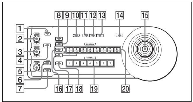
1 LOCK button and indicator
Press the LOCK button for more than one second, and the LOCK indicator lights and the values set by the VALUE/R, BRIGHT/B and FOCUS controls are locked. (The indicators of the locked controls are turned off.).
The AUTO/MANUAL button is also disabled. Press the LOCK button for more than one second again to unlock the controls and buttons.
2 VALUE/R control
When the brightness adjustment mode is selected with the MODE button (with the VALUE indicator lit), this control adjusts the value of the item (SHUTTER or IRIS) selected on the camera. When the white balance adjustment mode is selected with the MODE button (with the R indicator lit), this control adjusts the R. GAIN (red gain) (except the EVI-D30/D30P).
When the VALUE indicator is lit, the function of the control varies according to the exposure mode selected on the camera. For details, see “Functions of the VALUE and BRIGHT controls” on page 5.
3 BRIGHT/B control
When the brightness adjustment mode is selected with the MODE button (with the BRIGHT indicator lit), this control adjusts the value of the brightness of the camera, etc.
When the white balance adjustment mode is selected with the MODE button (with the B indicator lit), this control adjusts the B. GAIN (blue gain) (except the EVI-D30/D30P).
When the BRIGHT indicator is lit, the function of the control varies according to the exposure mode selected on the camera. For details, see “Functions of the VALUE and BRIGHT controls” on page 5.
Functions of the VALUE and BRIGHT controls
The functions of the VALUE control and the BRIGHT control change according to the exposure mode setting on the camera, as follows:
| Exposure mode on the camera | Function of VALUE control | Function of BRIGHT control |
| FULL AUTO | Not used | Exposure compensation level control* |
| SHUTTER Pri | Shutter speed control | Exposure compensation level control* |
| IRIS Pri | Iris control | Exposure compensation level control* |
| BRIGHT | Not used | Brightness level control |
| MANUAL | Shutter speed control | Iris control |
* When the exposure compensation function is activated on the camera.
4 MODE button
Press this button to select the function of the VALUE/R control and BRIGHT/L control. When the brightness adjustment mode is selected, the VALUE and BRIGHT indicators are lit. When the white balance adjustment mode is selected, the R and B indicators are lit.
5 FOCUS control
This control is enabled when MANUAL is selected with the AUTO/MANUAL button. Turn the control counterclockwise (toward NEAR) to focus on a near subject, and clockwise (toward FAR) to focus on a far subject.
6 AUTO/MANUAL button and AUTO indicator
Press this button to select focus mode AUTO or MANUAL.
When AUTO is selected, the AUTO indicator lights and the camera focuses automatically on the subject in the center of the screen. The FOCUS control and the ONE PUSH AF button are disabled.
When MANUAL is selected, the FOCUS control and the ONE PUSH AF button are enabled (with the FOCUS indicator lit).
7 ONE PUSH AF button
This button is enabled when MANUAL is selected with the AUTO/MANUAL button. Press the button to perform the one-push auto focus function (except the EVI-D30/D30P).
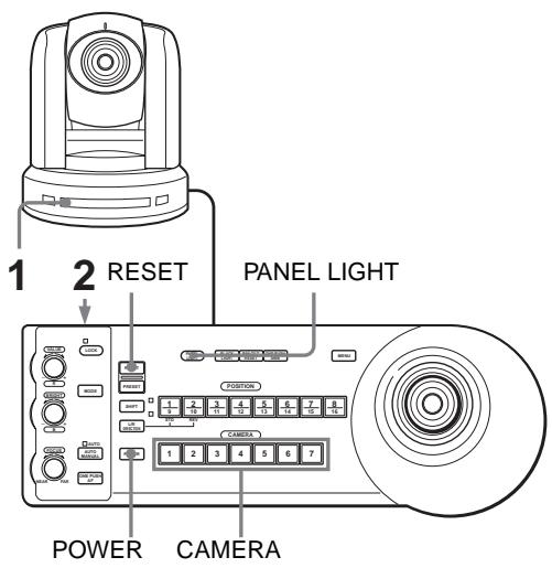
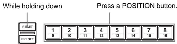
8 RESET button
Hold down this button and press POSITION button 1 to 16, and the memory of the camera corresponding to the pressed POSITION button is cleared to the factory-preset conditions.
When multiple cameras are connected, the camera addresses are set by holding down this button and pressing the POWER button.
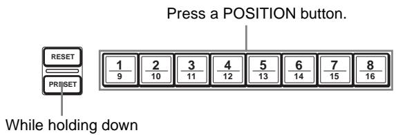
9 PRESET button
Hold down this button and press POSITION button 1 to 16, and the current camera settings are stored in the memory of the camera corresponding to the pressed POSITION button.
10 PANEL LIGHT button
Press this button to illuminate all the POSITION buttons and CAMERA buttons. Press the button again to turn off the illumination.
When the FULL AUTO exposure mode is selected on the camera, press this button to enable the backlight compensation function of the camera. Press it again to disable the function.
12 PAN-TILT RESET button
Press this button to reset the pan/tilt position of the camera to the initial conditions.
13 ONE PUSH AWB button
When the ONE PUSH white balance mode is selected on the camera, press this button to perform the one-push white balance adjustment.
14 MENU button
For the BRC-300/300P camera, press this button to display the menu of the camera, return to the main menu or turn off the menu.
For other cameras, press this button to turn the on-screen data display on or off.
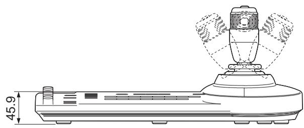
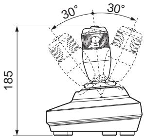
15 Joystick
The joystick is used for pan/tilt and zoom operations. Select the camera you want to control using the CAMERA buttons and operate the joystick.
Panning and tilting
When you incline the joystick right and left, the camera pans. When you incline it forward or backward, the camera tilts.
The pan/tilt speed changes according to the angle of the inclination.
When you release the joystick, the camera movement stops.
Zooming
When you turn the dial on the upper part of the joystick clockwise, the subject becomes larger (zoom in). When you turn it counterclockwise, the subject becomes smaller (zoom out).
To face the camera back to the front
When you press the button on the top of the joystick for one or two seconds with or without the menu displayed, the pan/tilt/zoom are reset and the camera returns to the front.
16 SHIFT button and indicators
Press this button for more than one second to select the function of the POSITION buttons for positions 1 to 8 or positions 9 to 16.
The upper indicator lights for positions 1 to 8, and the lower indicator for positions 9 to 16.
17 L/R DIRECTION button
The camera is preset to face toward the right whenever the joystick is inclined to the right. Hold down this button and press POSITION button 2 (REV) to reverse the pan direction to the direction in which you incline the joystick. To reset the direction, hold down this button and press POSITION button 1 (STD).
18 POWER button
Press this button to light the CAMERA button(s) corresponding to the status of the connected camera(s).
Blue: The power of the camera is on.
Yellow green: The camera is in standby mode.
Off: No camera is connected.
Hold down this button and press CAMERA button 1 to 7 to turn on/off the power of the camera corresponding to the pressed button.
19 CAMERA buttons
Press one of the buttons to select the camera from among those connected. The selected CAMERA button lights in blue.
20 POSITION buttons
You can store various camera settings such as the pan, tilt and zoom positions to the memory of the camera corresponding to each POSITION button, and load the settings in the memory.
Rear/Bottom
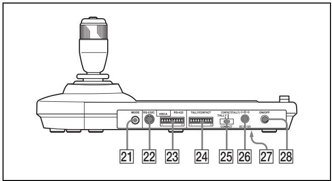
21 MODE selector
Select the position corresponding to the VISCA-controllable camera to be connected.
| Switch position | Camera mode |
| 0 | Automatically selected (default) |
| 1 | BRC-300/300P |
| 2 | EVI-D70/D70P |
| 3 | EVI-D100/D100P |
| 4 | EVI-D30/D30P |
22 VISCA RS-232C connector
Connect to the VISCA RS-232C IN connector of the camera or the BRU-300/300P Optical Multiplex Unit.
23 VISCA RS-422 connector
Connect to the VISCA RS-422 connector of the camera or the BRU-300/300P Optical Multiplex Unit.
An RS-422 connector plug is attached at the factory.
24 TALLY/CONTACT connector
This connector is used for the tally lamp input or the contact output.
Select the function of the connector using the TALLY/CONTACT selector.
An RS-422 connector plug is attached at the factory.
25 TALLY/CONTACT selector
Select the function of the TALLY/CONTACT connector.
TALLY: The tally lamp of the camera selected with the connected switcher lights.
CONTACT: The contact output corresponding to the camera address selected with this unit is short-circuited against the connected switcher.
CONTACT (TALLY): The contact output corresponding to the camera address selected with this unit is short-circuited against the connected switcher and the tally lamp of the camera selected with the connected switcher lights.
26 DC IN 12V connector
Connect the supplied AC power adaptor.
27 DIP switches (bottom)
Switch 1 (RS-232C/RS-422 selector)
Set to ON for RS-422, or OFF for RS-232C.
Switch 2 (Communication baud rate selector)
Set to ON for 38400bps, or OFF for 9600bps.
28 ON/OFF switch
Press this switch to turn on/off this unit.
Note
Set the switches before you turn on the power of this unit. Otherwise, the setting is not effective.
Connections and Operations
Connections
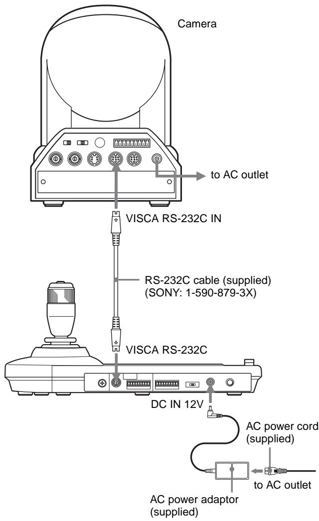
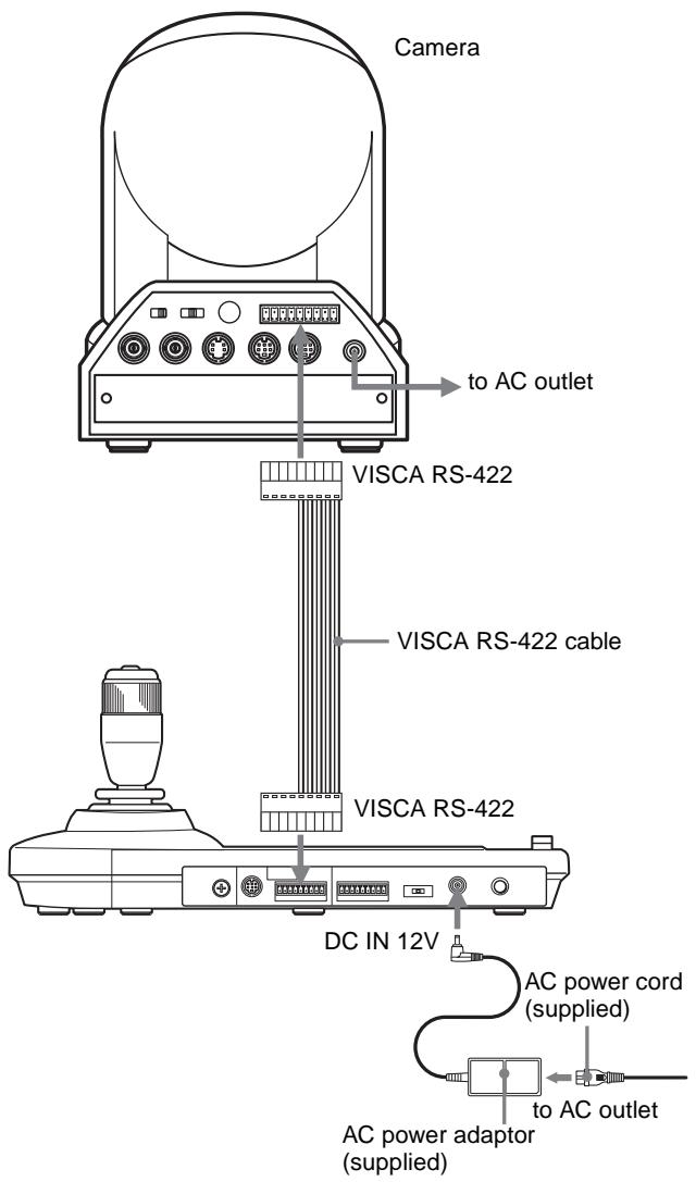
Connecting a Camera Equipped with a VISCA RS-232C Connector
1 Connect this unit to the camera using the RS-232C connecting cable supplied with this unit.
2 Connect this unit to an AC outlet using the supplied AC power adaptor and AC power cord.
Note
When using the VISCA RS-232C connectors, check that the DIP switch on the bottom of this unit (page 7) is set to RS-232C.
Connecting cables
Use the following connecting cable to connect devices in this system.
| Cable | Part No. | Number |
| RS-232C cable(3m (10feet)) | 1-590-879-3X | 1 |
RS-232C cable

Connecting a Camera Equipped with a VISCA RS-422 Connector
You can use the VISCA RS-422 connectors to connect this unit to the camera instead of the VISCA RS-232C connectors. Use of the VISCA RS-422 connectors allows the connection up to 1,200 m (3,937 feet) away. Prepare the connecting cable using the RS-422 connector plugs that come with this unit.
For making the cable, refer to the pin assignments of the VISCA RS-422 connector (page 17).
For the use of the RS-422 connector plugs, see page 18.
Notes
- When using the VISCA RS-422 connectors, check that the DIP switch on the bottom of this unit (page 7) is set to RS-422.
- When the connections using the VISCA RS-422 connectors are made, the VISCA RS-232C connection is not available.
Connecting Multiple Cameras Equipped with VISCA RS-232C Connector
Connections with the VISCA RS-232C cables (cross type) enable control of up to seven cameras with a single RM-BR300 Remote Control Unit.
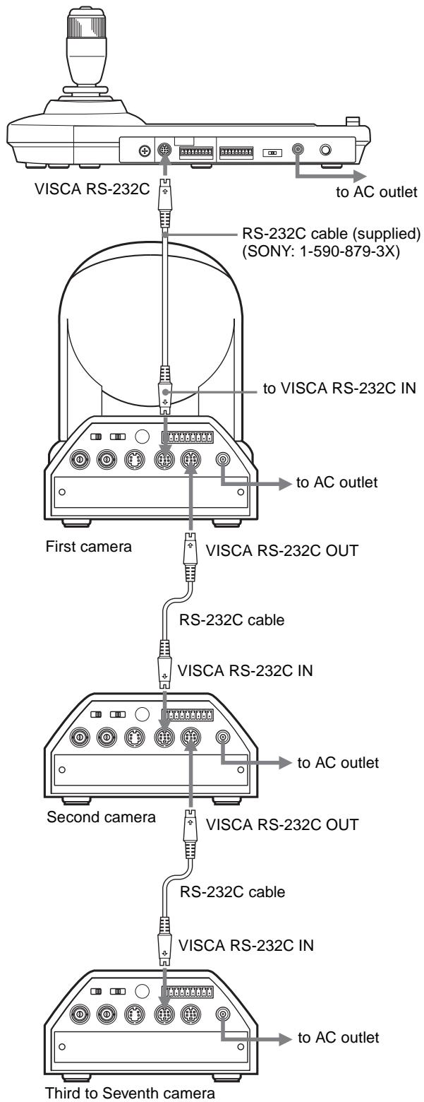
Note
When using the VISCA RS-232C connectors, check that the DIP switch on the bottom of this unit (page 7) is set to RS-232C.
To assign camera addresses
Before operating, you must assign the camera addresses to the connected cameras as follows. Then you can switch the camera to be controlled simply by pressing the corresponding CAMERA button.
1 Turn on the power of all the connected cameras and this unit.
2 Hold down the RESET button and press the POWER button on this unit.
The unit recognizes the connected cameras and assigns them camera addresses 1 to 7 automatically in the connected order.
3 Press the POWER button on this unit and check that the CAMERA buttons light.
The number of the lit CAMERA buttons indicates how many cameras have the addresses assigned. Now you can switch the camera you want to control by pressing the CAMERA button.
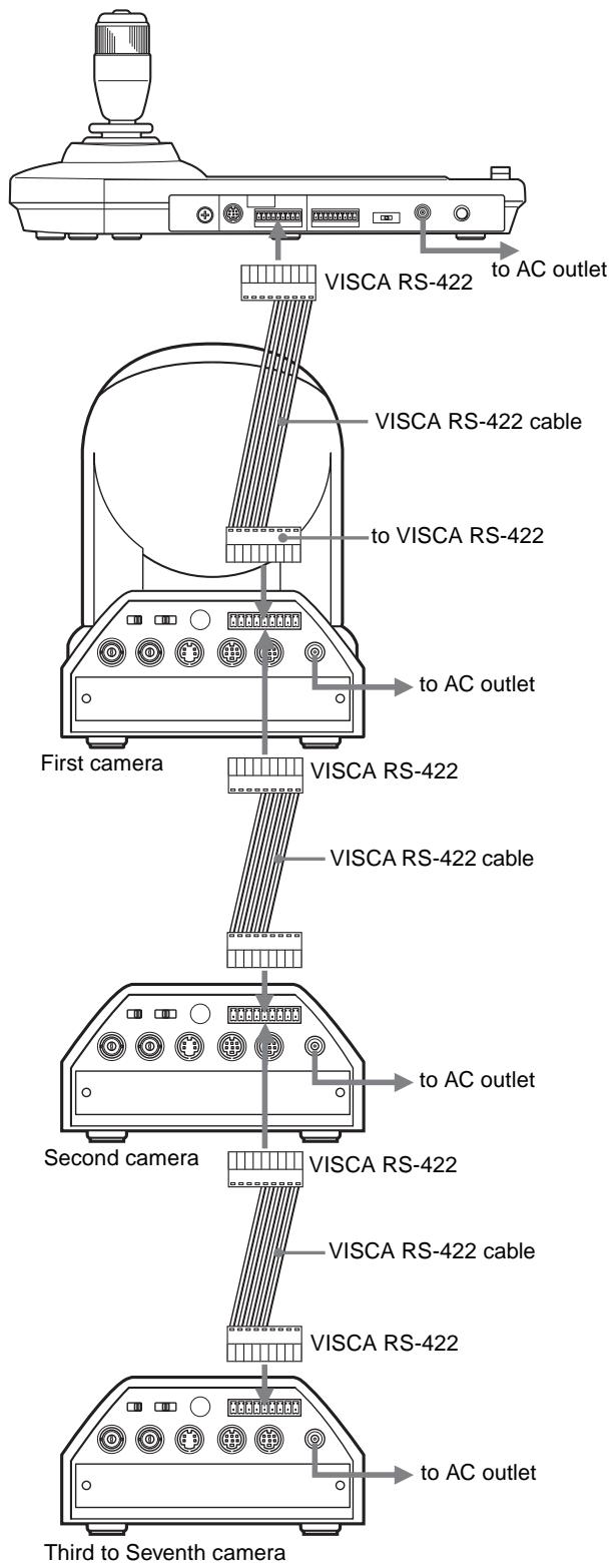
Connecting Multiple Cameras Equipped with VISCA RS-422 Connector
Connection via the VISCA RS-422 connectors enables control of multiple cameras. This allows the connection up to 1,200 m (3,937 feet) away.
Prepare the connecting cable using the RS-422 connector plug that comes with this unit.
For making the cable, refer to the pin assignments of the VISCA RS-422 connector (page 17).
For the use of the RS-422 connector plugs, see page 18. For the wiring diagram of VISCA RS-422 connection, refer to the Operating Instructions supplied with the BRC-300/300P.
Notes
- When using the VISCA RS-422 connectors, check that the DIP switch on the bottom of this unit (page 7) is set to RS-422.
- When the connections using the VISCA RS-422 connectors are made, the VISCA RS-232C connection is not available.
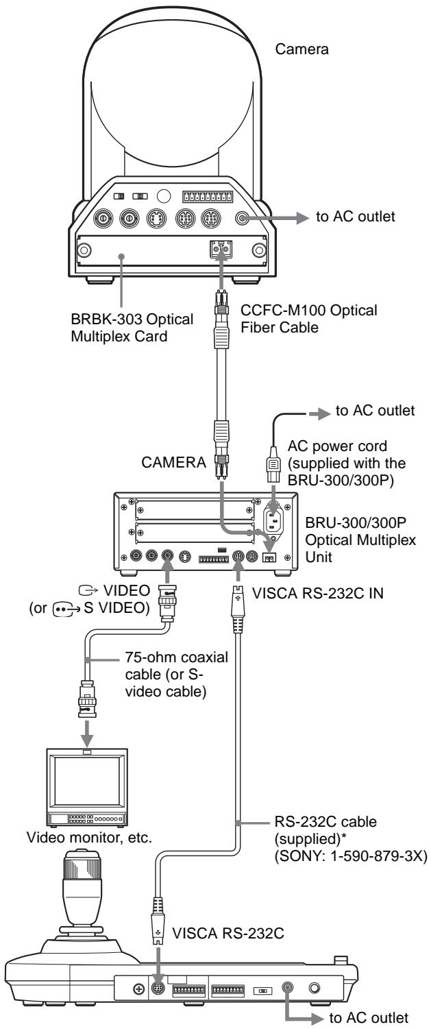
Connecting the BRU-300/300P Optical Multiplex Unit
You can control the camera using this unit via the BRU-300/300P Optical Multiplex Unit (not supplied).
flowchart
graph TD
    A["Camera"] -->|to AC outlet| B["BRBK-303 Optical Multiplex Card"]
    A -->|to AC outlet| C["CCFC-M100 Optical Fiber Cable"]
    A -->|to AC outlet| D["AC power cord (supplied with the BRU-300/300P)"]
    A --> E["CAMERA"]
    E --> F["BRU-300/300P Optical Multiplex Unit"]
    F --> G["VISCA RS-232C IN"]
    G --> H["75-ohm coaxial cable (or S-video cable)"]
    H --> I["Video monitor, etc."]
    I --> J["RS-232C cable (supplied)* (SONY: 1-590-879-3X)"]
    I --> K["VISCA RS-232C"]
    K --> L["to AC outlet"]
* The VISCA RS-422 connection is also available if you use the VISCA RS-422 connectors.
Notes
When using the VISCA RS-232C connectors or VISCA RS-422 connectors, check the VISCA FUNCTION switch on the rear of the Optical Multiplex Unit and the DIP switch on the bottom of this unit (page 7) are set to RS-232C or RS-422 correctly.
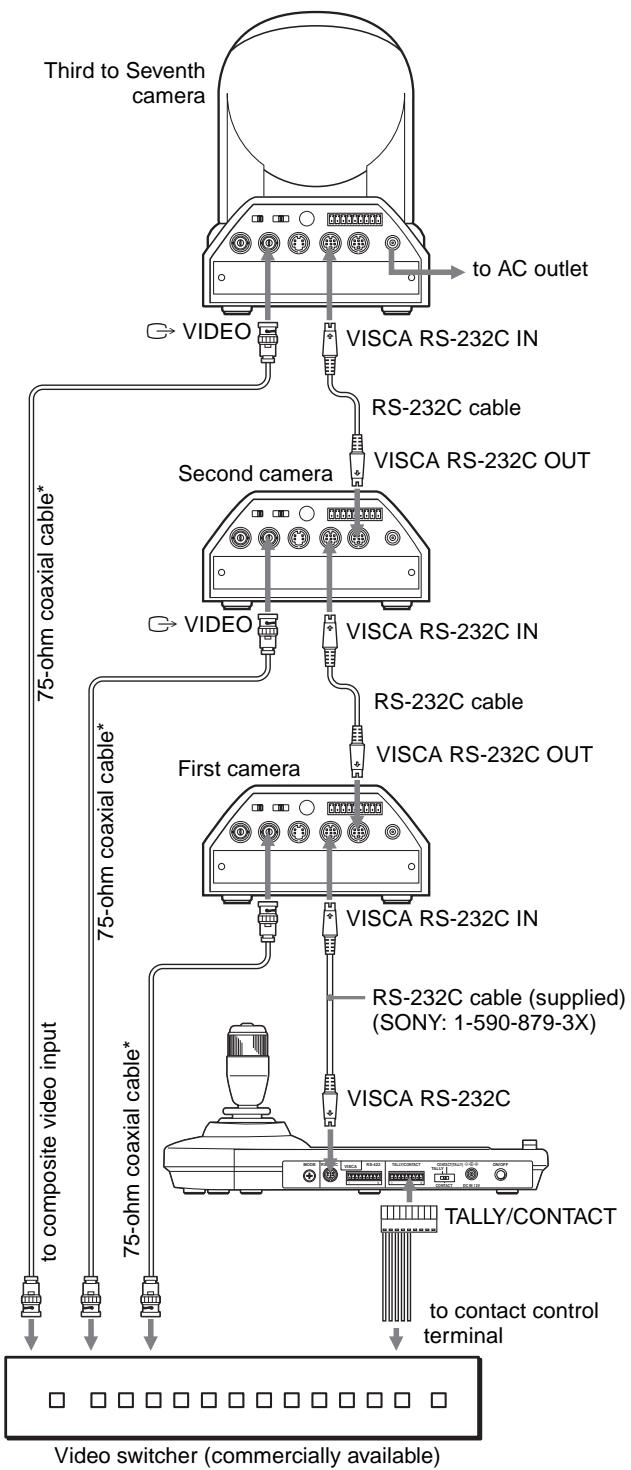
Connecting a Video Switcher
Use a commercially available contact-control type video switcher to switch between the multiple camera signals to be output.
flowchart
graph TD
    A["Third to Seventh camera"] -->|to AC outlet| B["Second camera"]
    A -->|to AC outlet| C["First camera"]
    B -->|RS-232C cable| D["VSICA RS-232C IN"]
    B -->|RS-232C OUT| E["VSICA RS-232C IN"]
    C -->|RS-232C cable| F["VSICA RS-232C IN"]
    C -->|RS-232C OUT| G["VSICA RS-232C IN"]
    H["75-ohm coaxial cable*"] --> I["75-ohm coaxial cable*"]
    J["75-ohm coaxial cable*"] --> K["75-ohm coaxial cable*"]
    L["75-ohm coaxial cable*"] --> M["75-ohm coaxial cable*"]
    N["75-ohm coaxial cable*"] --> O["75-ohm coaxial cable*"]
    P["75-ohm coaxial cable*"] --> Q["75-ohm coaxial cable*"]
    R["75-ohm coaxial cable*"] --> S["75-ohm coaxial cable*"]
    T["75-ohm coaxial cable*"] --> U["75-ohm coaxial cable*"]
    V["TV Switcher (commercially available)"] --> W["Video switcher (commercially available)"]
    X["TALLY/CONTACT"] --> Y["TALLY/CONTACT"]
    Z["to contact control terminal"] --> AA["to contact control terminal"]
* You can also use an S-video connecting cable to connect the 🐘→S VIDEO connector on the camera and the S-video input connector on the video switcher.
For connection with a video switcher, refer to the Operating Instructions of the switcher.
Turning on the Power
1 Connect the camera to an AC outlet.
The power of the camera is turned on and the POWER lamp lights.
The camera will automatically pan and tilt and be reset to the position stored in POSITION 1 (Pan/tilt reset action).
2 Press the ON/OFF switch on this unit to turn it on. The CAMERA button representing the camera whose power was turned off last lights. (CAMERA 1 button lights by default.)
3 Turn on the peripheral devices.
Notes
- Be sure to turn on the power of the camera before the power of this unit. Otherwise, the unit cannot recognize the connected camera.
- Do not touch the joystick when turning on the power of the unit. Doing so may affect the confirmation of the origin.
To turn on/off the camera using this unit
As long as the camera is connected to an AC outlet, you can turn the camera on or off with the POWER button on this unit.
While holding down the POWER button, press the CAMERA button corresponding to the camera whose power you want to turn on/off.
When you turn the power off using this unit, the POWER lamp turns off and the STANDBY lamp lights on the camera.
Storing the Camera Settings in Memory – Presetting Feature
Up to sixteen combinations of settings (sixteen positions), including camera position, zooming, focusing, and backlighting, can be stored in the memory of the camera using this unit.
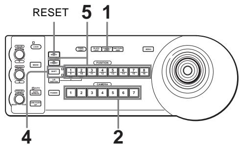
1 Press the PAN-TILT RESET button to reset the pan/tilt position.
2 Press the CAMERA button to select the camera whose settings you want to preset.
3 Adjust the position, zooming, focusing and backlighting of the camera.
4 Press the SHIFT button for more than one second to select the function of POSITION 1 to 8 buttons, if necessary.
To store in positions 1 to 8, press the SHIFT button so that the upper indicator lights. The POSITION 1 to 8 buttons can be used for positions 1 to 8. To store in positions 9 to 16, press the SHIFT button so that the lower indicator lights. The POSITION 1 to 8 buttons can be used for positions 9 to 16.

5 While holding down the PRESET button, press any of the POSITION buttons, 1 to 8, in which you want to store the settings.
The settings are stored in the memory of the camera.
The pressed button flashes during storing. Flashing stops when storing is completed.
To recall the stored settings
Select the function of the POSITION 1 to 8 buttons by pressing the SHIFT button for more than one second, if necessary. Press any of the POSITION buttons, 1 to 8, in which you have stored the settings.
To cancel the preset memory
Select the function of the POSITION 1 to 8 buttons using the SHIFT button, if necessary. While holding down the RESET button, press the POSITION button from which you want to cancel the settings.
The pressed button flashes during canceling of the settings. Flashing stops when the settings have been canceled.
Notes
- When the power is turned on, the camera starts with the settings stored in POSITION 1.
- If you want to retain the previous pan and tilt positions when the power is turned off and turned on again, store those positions in POSITION 1.
- When you are storing or canceling the settings in one POSITION, you cannot call up, store or cancel the settings in another POSITION.
Setting the Speed of the Camera Moving to a Preset Position (BRC-300/300P only)
You can select the panning/tilting speed when the camera moves to a preset position.
1 Press the CAMERA button to select the camera whose speed you want to set.
2 Press the POSITION button for which you want to set the speed for more than one second.
All the CAMERA buttons, 1 to 7, flash.
3 Press one of the CAMERA buttons to select the speed.
| CAMERA button | Panning/tilting speed |
| 1 | 1 degree/sec. |
| 2 | 2.2 degrees/sec. |
| 3 | 4.8 degrees/sec. |
| 4 | 11 degrees/sec. |
| 5 | 23.3 degrees/sec. |
| 6 | 43 degrees/sec. |
| 7 | 60 degrees/sec. (default) |
Now the camera will move to the position preset to the pressed POSITION button with the selected speed.
Troubleshooting
Before bringing in your unit for service, check the following as a guide to troubleshoot the problem. If the problem cannot be corrected, consult with your Sony dealer.
| Symptom | Cause | Remedy |
| The power of the unit is not turned on. | The AC power adaptor is not connected to the DC IN 12V jack firmly. | Insert the power cord firmly as far as it will go. |
| The AC power cord is not inserted firmly into the AC power adaptor or the AC outlet. | Insert the power cord firmly as far as it will go. | |
| The camera cannot be operated with the unit. | The connection using the VISCA RS-422 connectors is not correctly made. | Check that the connection to the VISCA RS-422 connectors is correctly made, and the RS-422 cable is properly connected. |
| VISCA control setting is not correct. | Select the proper setting (RS-232C or RS-422) with the DIP switch on the unit (page 7). | |
| The communication baud rate setting of the camera and the unit differ. | Select the communication baud rate, 9,600 bps or 38,400 bps, with the DIP switch on the unit (page 7) which is selected on the camera. | |
| The unit cannot be operated at all. | — | Pull out the plug of the power cord from the AC outlet, then reinsert it into the AC outlet after a while. |
Specifications
Input/output connectors
Control input/output
VISCA RS-232C OUT: Mini DIN 8-pin type
VISCA RS-422: 9-pin type
TALLY IN/CONTACT OUT: 9-pin type
Control signal format
9600 bps/38400 bps
Data: 8 bit
Stop bit: 1
Power connector
JEITA type4 (DC IN 12V)
General
Input voltage 12 V DC (10.8 to 13.2 V DC)
Current consumption
0.2 A max. (at 12 V DC), 2.4W
Operating temperature
0^ to +40^ (32°F to 104°F)
Storage temperature
-20°C to +60°C (-4°F to 140°F)
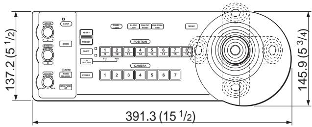
Dimensions 391.3× 185× 145.9mm (w/h/d)
(15^1/2×7^3/8×5^3/_4 inches)
(excluding protruding parts)
Mass Approx. 950 g (2 lb 15 oz)
Supplied accessories
AC power adaptor (1)
AC power cord (1)
RS-232C connecting cable (1)
RS-422 connector plug (2)
Operating Instructions (1)
Design and specifications are subject to change without notice.
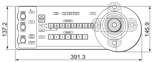
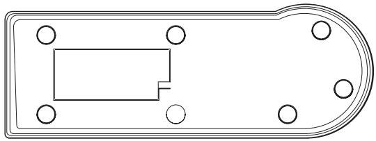
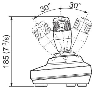
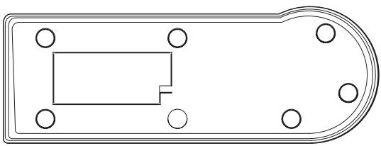
Dimensions
Top
Front
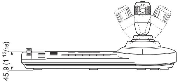
Side
Bottom

natural_image
Pure technical line drawing of a mechanical component with no text or symbolsUnit: mm (inches)
Pin Assignments
VISCA RS-232C output connector (mini DIN 8-pin, female)
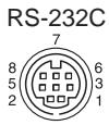
| Pin No. | Function |
| 1 | No Connection |
| 2 | No Connection |
| 3 | TXD IN |
| 4 | GND |
| 5 | RXD IN |
| 6 | GND |
| 7 | No Connection |
| 8 | No Connection |
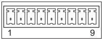
VISCA RS-422 connector (connector plug, 9-pin)
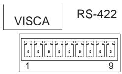
| Pin No. | Function |
| 1 | No Connection |
| 2 | No Connection |
| 3 | No Connection |
| 4 | No Connection |
| 5 | GND |
| 6 | RXD IN- |
| 7 | RXD IN+ |
| 8 | TXD IN- |
| 9 | TXD IN+ |
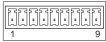
TALLY/CONTACT connector (connector plug, 9-pin)
TALLY/CONTACT
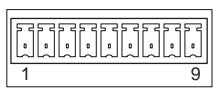
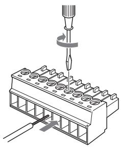
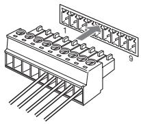
Using the VISCA RS-422 Connector Plug
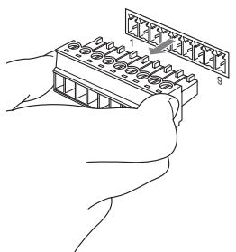
1 Grasp both ends of the VISCA RS-422 connector plug and pull it out as shown in the illustration.
natural_image
Line drawing of hands assembling a grid-like electronic component (no text or symbols)2 Insert a wire (AWG Nos. 28 to 18) into the desired wire opening on the plug, and tighten the screw for that wire using a flat-head screwdriver.
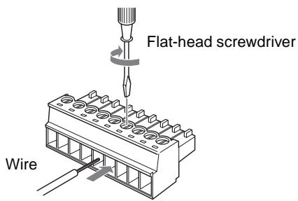
3 Insert the VISCA RS-422 connector plug into the VISCA RS-422 connector.

natural_image
Technical illustration of a 16-pin connector with pin numbering and mounting holes (no text or symbols)Notes
- In order to stabilize the voltage level of the signal, connect both ends to GND.
- When the connections using the VISCA RS-422 connectors are made, the VISCA RS-232C connection is not available.
- The maximum connection distance with the VISCA RS-422 connection is approximately 1,200 m (3,937 feet).
AVERTISSEMENT
Face inférieure

natural_image
Top-down schematic of a mechanical component with circular holes and a rectangular slot (no text or symbols)Unité : mm (pouces)
Brochage
natural_image
Line drawing of hands holding a device with labeled components (no text or symbols present)natural_image
Technical illustration of a 16-pin connector with pin headers and a labeled section (no text or symbols beyond basic labels)Remarques
24 Conector TALLY/CONTACT
25 Selector TALLY/CONTACT
26 Conector DC IN 12V
Parte inferior
natural_image
Top-down schematic of a mechanical component with circular holes and a rectangular slot (no text or symbols)natural_image
Line drawing of a hand holding a device with labeled parts (no text or symbols present)natural_image
Technical illustration of a connector pin assembly with numbered components (no text or symbols)Notas
natural_image
Technical line drawing of a mechanical device with a central fan and base plate, showing dimension标注 (no text or symbols present)Seite
Unterseite

natural_image
Pure technical line drawing of a mechanical component with no text or symbolsEinheit: mm
Stiftbelegung
natural_image
Line drawing of hands holding a device with numbered components (no text or symbols)natural_image
Technical illustration of a connector pin assembly with numbered components (no text or symbols)Hinweise
Printed on 100% recycled paper.
お問い合わせは