
TECHCLIM9 - Air Conditioning TELEFUNKEN - Free user manual and instructions
Find the device manual for free TECHCLIM9 TELEFUNKEN in PDF.
| Product Type | Monoblock mobile air conditioner |
| Brand | Telefunken |
| Model | TECHCLIM9 |
| Net weight | 32.5 kg |
| Power supply | 220-240 V ~ 50 Hz |
| Protection class | Class I |
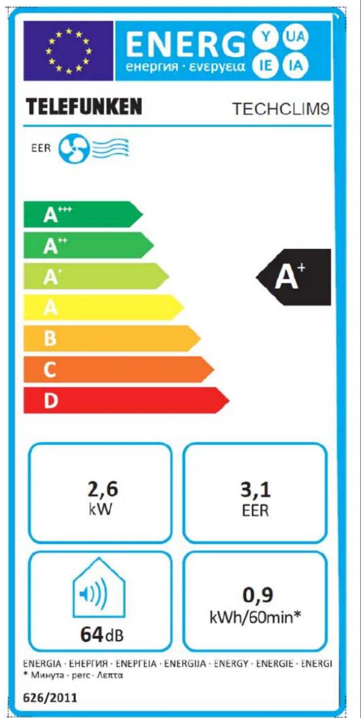
| Nominal cooling power | 2.6 kW (9000 Btu/h) |
| Nominal power consumption | 0.87 kW |
| Max power consumption | 0.97 kW |
| Energy efficiency ratio (EER) | 3.1 |
| Energy class | A+ |
| Noise level | ≤ 64 dB(A) |
| Air flow rate | 350 m³/h |
| Refrigerant | R290 / 200 g |
| Operating modes | Cooling, Ventilation, Dehumidification, Auto |
| Remote control | Yes (2 AAA batteries) |
| Timer | 0.5 to 24 hours |
| Special functions | Health (negative ions), iClean, Anti-F, Turbo, Sleep, Eco |
| Oscillation | Vertical and horizontal (remote control) |
| Filters | 2 washable air filters |
| Drainage | Manual via plug or hose, partial auto-evaporation |
| Exhaust hose length | 30 to 160 cm (adapter included) |
| Box contents | Unit, remote control, exhaust hose, window adapter, drainage kit |
| Recommended maintenance | Clean filters every 2 weeks, drain if P1 display |
Frequently Asked Questions - TECHCLIM9 TELEFUNKEN
User questions about TECHCLIM9 TELEFUNKEN
0 question about this device. Answer the ones you know or ask your own.
Ask a new question about this device
Download the instructions for your Air Conditioning in PDF format for free! Find your manual TECHCLIM9 - TELEFUNKEN and take your electronic device back in hand. On this page are published all the documents necessary for the use of your device. TECHCLIM9 by TELEFUNKEN.
USER MANUAL TECHCLIM9 TELEFUNKEN
- READ CAREFULLY THE INSTRUCTIONS BEFORE INSTALLING AND USING THIS APPLIANCE. IN THE CASE YOU RESELL THIS APPLIANCE, PLEASE MAKE SURE TO PROVIDE THIS INSTRUCTION MANUAL TO YOUR BUYER.
WARNING: BEFORE USING YOUR APPLIANCE, THE UNIT HAS TO BE POSITIONED UPRIGHT FOR AT LEAST 2 HOURS TO STABILIZE THE REFRIGERANT GAS.
- THIS APPLIANCE IS INTENDED TO BE USED IN HOUSEHOLD AND SIMILAR APPLICATIONS SUCH AS:
STAFF KITCHEN AREAS IN SHOPS, OFFICES AND OTHER WORKING ENVIRONMENTS;
FARM HOUSES;
BY CLIENTS IN HOTELS, MOTELS AND OTHER RESIDENTIAL TYPE OF ENVIRONMENTS;
BED AND BREAKFAST TYPE ENVIRONMENTS.
-
IT SHOULD NOT BE USED FOR ANY OTHER PURPOSE OR IN ANY OTHER APPLICATION, SUCH AS FOR NON-DOMESTIC USE OR IN A COMMERCIAL ENVIRONMENT. ANY COMMERCIAL USE, INAPPROPRIATE USE OR FAILURE TO COMPLY WITH THE INSTRUCTIONS, THE MANUFACTURER ACCEPTS NO RESPONSIBILITY AND THE GUARANTEE WILL NOT APPLY.
-
THE APPLIANCE CAN BE USED BY CHILDREN AGED FROM 8 YEARS AND ABOVE AND PERSONS WITH REDUCED PHYSICAL, SENSORY OR MENTAL CAPABILITIES, OR LACK OF EXPERIENCE AND KNOWLEDGE, UNLESS THEY HAVE BEEN GIVEN SUPERVISION OR INSTRUCTION CONCERNING USE OF THE APPLIANCE IN A SAFE WAY AND UNDERSTAND THE HAZARDS INVOLVED BY A PERSON RESPONSIBLE FOR THEIR SAFETY. CHILDREN SHALL NOT PLAY WITH THE APPLIANCE. CLEANING
AND MAINTENANCE SHALL NOT BE MADE BY CHILDREN WITHOUT SUPERVISION.
- KEEP AWAY THIS APPLIANCE AND ITS ELECTRIC PLUG FROM CHILDREN UNDER 8 YEARS OLD.
- THE APPLIANCE MUST NOT BE USED IF IT HAS BEEN DROPPED, IF IT HAS ANY VISIBLE DAMAGE, IF IT LEAKS OR IF IT FUNCTIONS ABNORMALLY IN ANY WAY.
- IF THE SUPPLY CORD IS DAMAGED, IT MUST BE REPLACED BY THE MANUFACTURER, ITS SERVICE AGENT OR SIMILARLY QUALIFIED PERSONS IN ORDER TO AVOID A HAZARD.
- THE APPLIANCE SHALL BE USED IN ACCORDANCE WITH NATIONAL WIRING REGULATIONS.
FOR THE DETAILS ON HOW TO CLEAN THE UNIT, PLEASE SEE SECTION « CLEANING AND MAINTENANCE » - REGARDING THE INFORMATION ON INSTALLATION AND OPERATING SETTING, THANKS TO REFER TO THE BELOW PARAGRAPH OF THE MANUAL « SET-UP AND USE »
DO NOT BEND OR CRUSH THE EXHAUST HOSE. - DO NOT INCLINE YOUR APPLIANCE OVER 35^ WHEN MOVING IT. AVOID ANY VIBRATIONS OR SHOCK.
- THE APPLIANCE IS EQUIPPED WITH A COMPRESSOR PROTECT SYSTEM, THEREFORE THE UNIT NEEDS 5 MINUTES TO START WORKING AFTER EACH STOP.
- NEVER DISASSEMBLE AND REPAIR THE UNIT YOURSELF, IT MAY PRESENT HAZARDS. DO NOT EXTEND THE EXHAUST HOSE ON YOUR OWN, THIS COULD DAMAGE THE UNIT.
- THIS PRODUCT CONTAINS FLUORINATED GASES. CHEMICAL NAME OF THE PROPANE GAS: R290. THE PROPANES GASES ARE CONTAINED IN HERMETICALLY SEALCD EQUIPMENT. THE ELECTRICAL SWITCHGEAR HAS A TESTED LEAKAGE RATE OF
LESS THAN 0.1% PER YEAR AS SET OUT IN THE TECHNICAL SPECIFICATION OF THE MANUFACTURER. PLEASE FIND AS BELOW THE QUANTITY OF FLUORINATED GREENHOUSE GASES FOR WHICH THE EQUIPMENT IS DESIGNED AND THE GLOBAL WARMING POTENTIAL OF THOSE GASES FOR EACH OF OUR AIR CONDITIONNER.
| BRAND | MODEL | GAS TYPE | GWP | UNIT GAS WEIGHT | TEQ CO2 BY UNIT |
| Telefunken | TECHCLIM9 | R290 | 3.3 | 200 gr | 0.00066 |
| Telefunken | TECHCLIM12 | R290 | 3 | 210 gr | 0.00063 |
- R290 REFRIGERANT GAS COMPLIES WITH EUROPEAN ENVIRONMENTAL DIRECTIVES. NEVER PERFORATE ANY PART OF THE REFRIGERANT CIRCUIT ON THE APPLIANCE.
- DO NOT LOAD MORE THAN 250G OF R290 PER APPLIANCE.
- WARNING: BE AWARE THAT REFERIGERANT MAY NOT CONTAIN AN ODOUR.
DO NOT PIERCE OR BURN. - APPLIANCE SHALL BE INSTALLED, OPERATED AND STORED IN A ROOM WITH A FLOOR AREA LARGER THAN 12M2.
- THE APPLIANCE SHALL BE STORED IN A ROOM WITHOUT CONTINUUSLY OPERATING IGNITION SOURCES (FOR EXAMPLE: OPEN FLAMES, AN OPERATING GAS APPLIANCE OR AN OPERATING ELECTRIC HEATER).
-ServICING SHALL ONLY PERFORMED BY A REFRIGERANT SPECIALIST. - ANY PERSON WHO IS INVOLVED WITH WORKING ON OR BREAKING INTO A REFRIGERANT CIRCUIT SHOULD HOLD A CURRENT VALID CERTIFICATE FROM AN INDUSTRY-ACCREDITED ASSESSMENT AUTHORITY. WHICH AUTHORIZES
THEIR COMPETENCE TO HANDLE REFRIGERANTS SAFETY IN ACCORDANCE WITH AN INDUSTRY RECOGNIZED ASSESSMENT SPECIFICATIONS.
- SERVICING SHALL ONLY BE PERFORMED AS RECOMMENDED BY THE EQUIPMENT MANUFACTURER. MAINTENANCE AND REPAIR REQUIRING THE ASSITANCE OF OTHER SKILLED PERSONNEL SHALL BE CARRIED OUT UNDER THE SUPERVISION OF THE PERSON COMPETENT IN THE USE OF FLAMMABLE REFRIGERANTS.
- WARNING: DO NOT USE MEANS TO ACCELERATE THE DEFROSTING PROCESS OR TO CLEAN, OTHER THAN THOSE RECOMMENDED BY THE MANUFACTORY.
- WARNING: DO NOT DAMAGE THE REFRIGERANT CIRCUIT.
- SIGNIFICATION DES SYMBOLES UTILISÉS DANS LA NOTICE ET APPOSES SUR LE PRODUIT :
Attention
WARNING: RISK OF FIRE, FLAMMABLES MATERIALS.
THIS APPLIANCE IS FILLED WITH R290 PROpane GAS. R290 IS A NATURAL GAS BUT FLAMMABLE.
IF A LEAK IS DETECTED, AVOID CONTACT WITH POTENTIAL FLAMES OR SOURCES OF FIRE AND AERATE THE PART IN WHICH THE APPLIANCE IS STORED. DO NOT USE THE APPLIANCE, CONTACT THE MANUFACTURER, ITS SERVICE AGENT OR SIMILARLY QUALIFIED PERSONS IN ORDER TO AVOID A HAZARD.
PLEASE READ OPERATOR'S MANUAL CAREFULLY!
| i | PLEASE READ OPERATING INSTRUCTIONS CAREFULLY! |
| VEUILLEZ LIRE ATTENTIVEMENT LES DONNÉES TECHNIQUES, D'INSTALLATION ET DE RÉPARATION DE L'APPAREIL! PLEASE READ TECHNICAL MANUAL, INSTALLATION AND SERVICING CAREFULLY! |
- WARNING: TO AVOID OVERHEATING, DO NOT COVER THE APPLIANCE.
- DO NOT OBSTRUCT ANY VENTILATION OPENINGS. KEEP ALL THE VENTILATION CLEAR OF OBSTRUCTION.
- THE APPLIANCE SHALL BE STORED SO AS TO PREVENT MECHANICAL DAMAGE FROM OCCURING.
- WARNING: DO NOT USE THIS APPLIANCE CLOSED TO ANY SINK, TUB, SHOWER OR SWIMMING POOL.
SAFETY CAUTIONS
- AFTER UNPACKING THE APPLIANCE, MAKE SURE IT IS NOT DAMAGED. IN CASE OF DOUBT, DO NOT USE THE APPLIANCE AND CONTACT YOUR SUPPLIER OR A QUALIFIED TECHNICIAN.
- THE USE OF ACCESSORY AND ATTACHMENTS NOT RECOMMENDED BY THE MANUFACTURER MAY CAUSE INJURIES.
- ALWAYS UNPLUG THE APPLIANCE IF NOT USING IT FOR A PERIOD OF TIME.
- REMOVE ALL PACKAGING AND DO NOT LEAVE THE PACKAGING MATERIAL SUCH AS PLASTIC BAGS, POLYSTYRENE AND ELASTIC
BANDS IN EASY REACH OF CHILDREN AS THEY MAY CAUSE SERIOUS INJURIES.
- AFTER UNPACKING YOUR APPLIANCE, MAKE SURE YOU HAVE PUT IT ON A FLAT, STABLE AND HEAT-RESISTANT SURFACE. CHECK YOU HAD LEAVE ENOUGH SPACE BETWEEN YOUR APPLIANCE AND SURROUNDING WALL TO LET THE AIR CIRCULATE AROUND THE UNIT. THERE SHOULD BE AT LEAST 60CM ON THE TOP AND 50CM ON SIDES APART FROM THE UNIT. DO NOT PUT ANYTHING INTO THE VENTILATION SLITS, OR OBSTRUCT THEM WITH FABRICS.
- DO NOT USE YOUR UNIT OUTSIDE. DO NOT INSTALL IN FULL SUN OR IN A LOCAL WITH HIGH RISK OF FIRE. FOR YOUR OWN SAFETY, WE RECOMMEND YOU NEVER LEAVE THE APPLIANCE IN A PLACE THAT IS EXPOSED TO INCLEMENT WEATHER CONDITION.
- THIS APPLIANCE MUST BE EARTHED. DO NOT USE AN EXTENSION LEAD. CHECK THAT THE VOLTAGE MARKED ON THE RATING PLATE MATCHES TO YOUR LOCAL SUPPLY. IF NOT THE CASE, DO NOT USE THE APPLIANCE AND SEEK FOR EXPERT ADVICE.
- TO AVOID OVERHEATING DO NOT COVER THE UNIT.
- AVOID TO PLACE IT CLOSE TO ANY HEAT SOURCES, OBJECTS, GAS OR FLAMMABLE MATERIALS.
- DO NOT PUT HEAVY OBJECTS ON THE APPLIANCE.
- DO NOT PUT THIS APPLIANCE ON TOP OF OTHERS.
- DO NOT INSERT YOUR FINGERS OR ANY OBJECTS THROUGH THE APPLIANCE'S GRID.
-
DO NOT INCLINE YOUR APPLIANCE WHEN MOVING IT. AVOID ANY VIBRATIONS OR SHOCK. NEVER MOVE THE APPLIANCE WHEN IN USE.
-
CHILDREN SHALL NOT PLAY WITH THE APPLIANCE AND CLIMB ON THE APPLIANCE.
- WHEN THE UNIT IS FUNCTIONING, KEEP AN EYE ON CHILDREN AND PETS.
- DO NOT EXPOSE DOMESTIC ANIMALS OR PLANTS TO PROLONGED DIRECT AIR FLOW.
- NEVER USE PESTICIDES, OIL, DETERGENTS OR PAINTING SPRAY ON OR AROUND THE APPLIANCE.
- TAKE ALL NECESSARY MEASURE WITH CORDS AND EXTENSIONS TO AVOID ANY INJURIES WHILE IN USE.
- DO NOT USE THIS APPLIANCE IN THE IMMEDIATE SURROUNDINGS OF A BATH, A SHOWER OR A SWIMMING POOL. AVOID WATERS' SPLASHING ON THE UNIT.
- NEVER LEAVE APPLIANCE PLUGGED IN WHEN NOT IN USE.
- NEVER IMMERSE IN WATER OR ANY OTHER LIQUID THIS APPLIANCE, ITS ELECTRIC PLUG AND CORD.
- THE SUPPLY CORD SHOULD BE REGULARLY EXAMINED FOR SIGNS OF DAMAGE AND THE APPLIANCE IS NOT TO BE USED IF THE CORD IS DAMAGED.
- NEVER PLUG THE APPLIANCE WITH WET HANDS.
- NEVER USE THE APPLIANCE WITH BARE OR WET FEET.
- NEVER UNPLUG THE APPLIANCE BY PULLING THE POWER CABLE. ALWAYS UNPLUG THE APPLIANCE FROM THE MAINS SOCKET.
- ALWAYS UNPLUG THE APPLIANCE BEFORE ANY CLEANING OPERATION.
STANDARDS
THIS APPLIANCE IS CONFORMED TO CURRENT DIRECTIVES AND STANDARDS.
TABLE OF CONTENTS
DESCRIPTION 1
SET-UP AND USE 2
Installation 2
Using your appliance. 5
CLEANING AND MAINTENANCE 9
TROUBLESHOOTING 12
TECHNICAL INFORMATION 13
SERVICING AND REPAIRING INSTRUCTION 14
DESCRIPTION
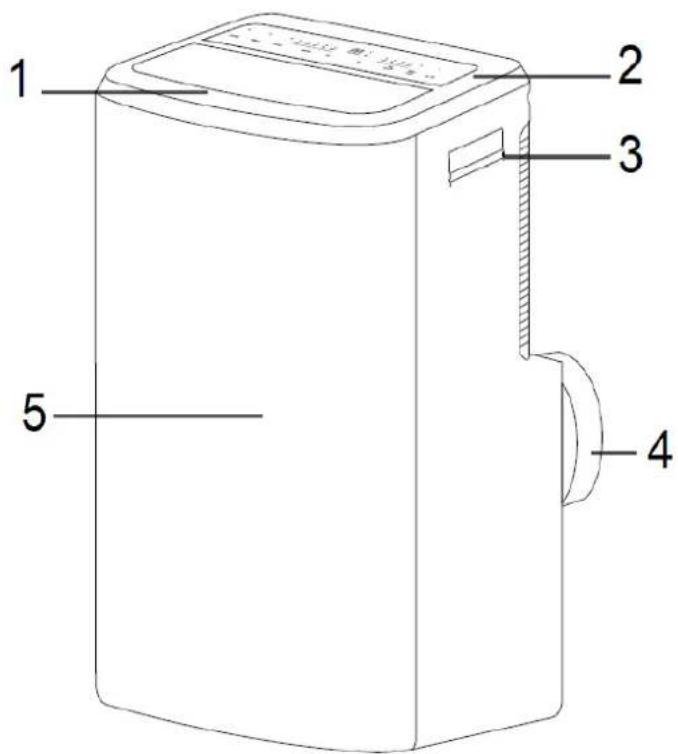
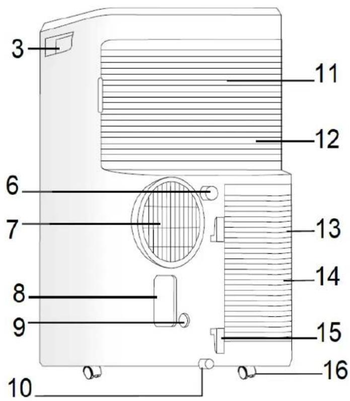
- Room air outlet
- LCD display
- Handle
- Connector for 19C
- Body
- Dehumidifying drain outlet
- Exhaust air outlet
- Plug fixing
- Pump drain outlet
- Bottom tank drain outlet
- Air filter (behind the grid)
- Air inlet
- Air filter (behing the grid)
- Air inlet
- Power cord storage
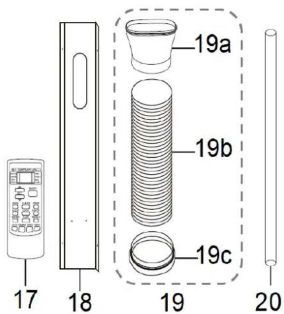
16.Wheels - Remote control
- Windows kit
- Exhaust hose
19a. Window adapter
19b.Hose
19c. Adapter for body connector
- Drain hose
SET-UP AND USE
Installation
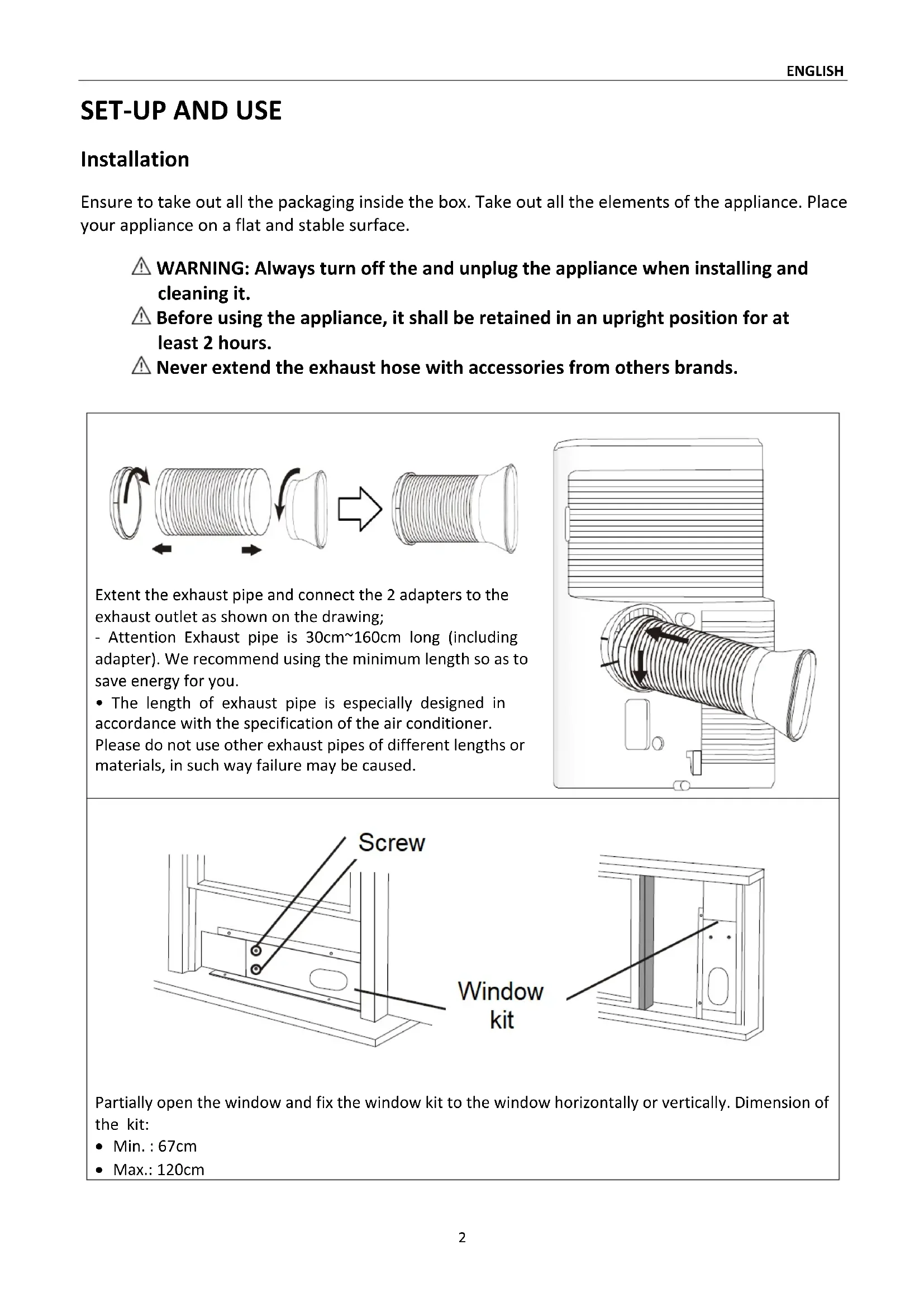
Ensure to take out all the packaging inside the box. Take out all the elements of the appliance. Place your appliance on a flat and stable surface.
WARNING: Always turn off the and unplug the appliance when installing and cleaning it.
Before using the appliance, it shall be retained in an upright position for at least 2 hours.
Never extend the exhaust hose with accessories from others brands.
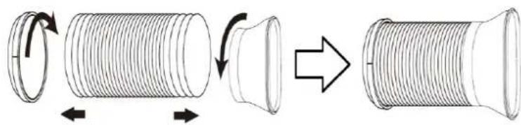
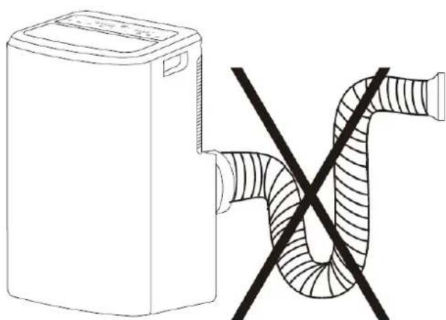
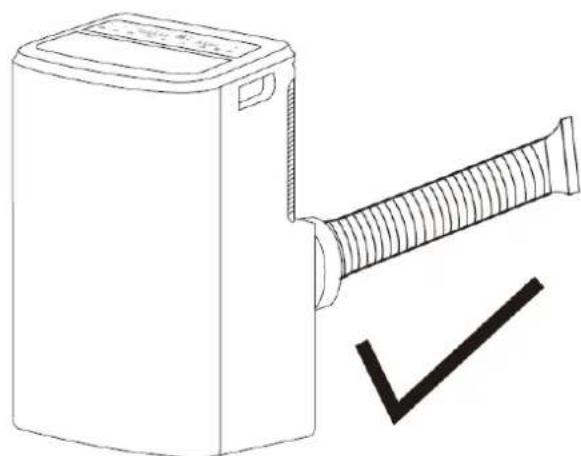
Extent the exhaust pipe and connect the 2 adapters to the exhaust outlet as shown on the drawing;
-
Attention Exhaust pipe is 30cm 160cm long (including adapter). We recommend using the minimum length so as to save energy for you.
-
The length of exhaust pipe is especially designed in accordance with the specification of the air conditioner. Please do not use other exhaust pipes of different lengths or materials, in such way failure may be caused.
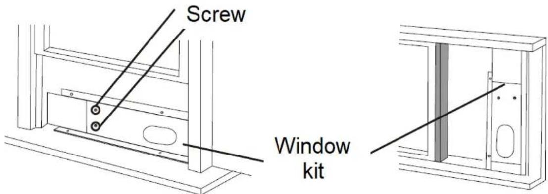
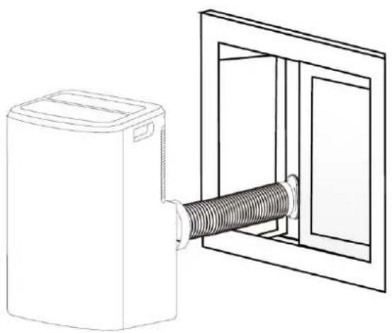
Partially open the window and fix the window kit to the window horizontally or vertically. Dimension of the kit:
Min.:67cm
Max.: 120cm
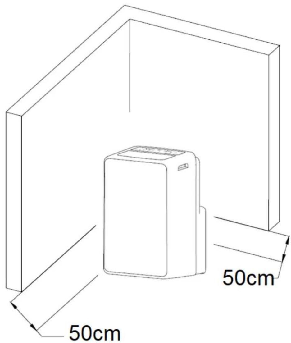
Choose an appropriate location for your appliance and keep at least 50cm from any walls and objects.
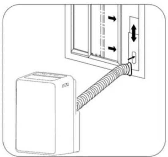
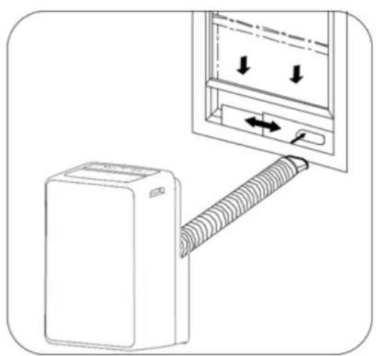
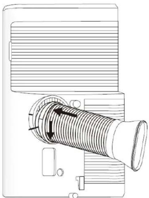
Fix the hose adaptor to the air outlet of the window kit.
Installing without the window kit.
For wall mounting installation, follow below figure:
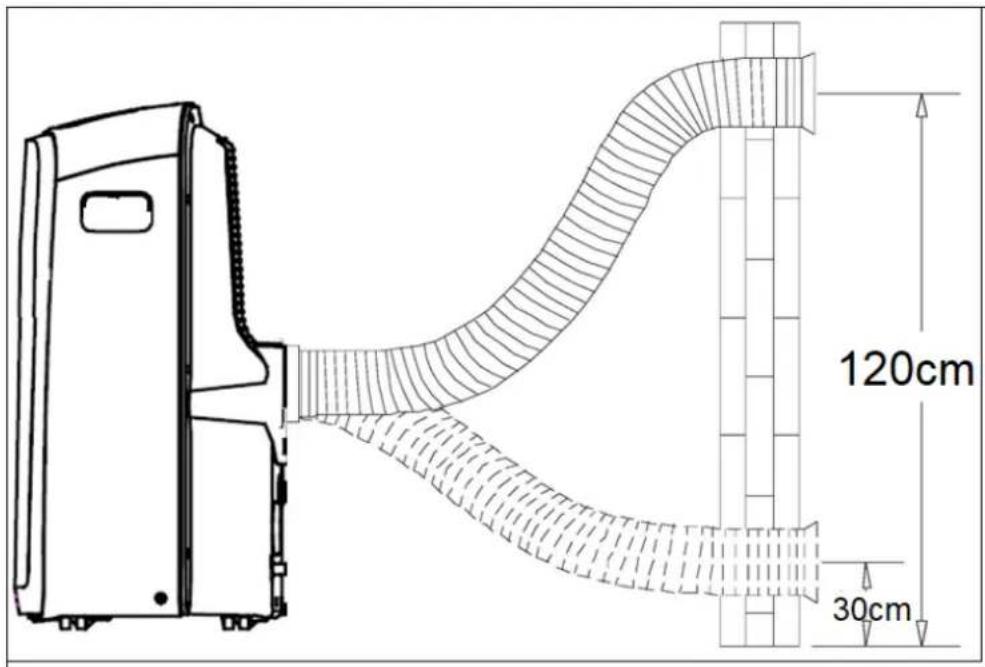
Attention, wall installation requires a specific connector not supplied. Please contact the manufacturer or the after sales services to purchase this connector.
Bad versus good setting of the exhaust pipe:
Using your appliance
- Place your appliance on a flat, dry and stable surface with a 50~cm away from any walls and objects.
Plug your unit to a socket.
1. Electronic control panel and remote control
Note: The control panel and remote control share common keys, and therefore have the same description numbers. The remote control has additional function keys indicated by letters.
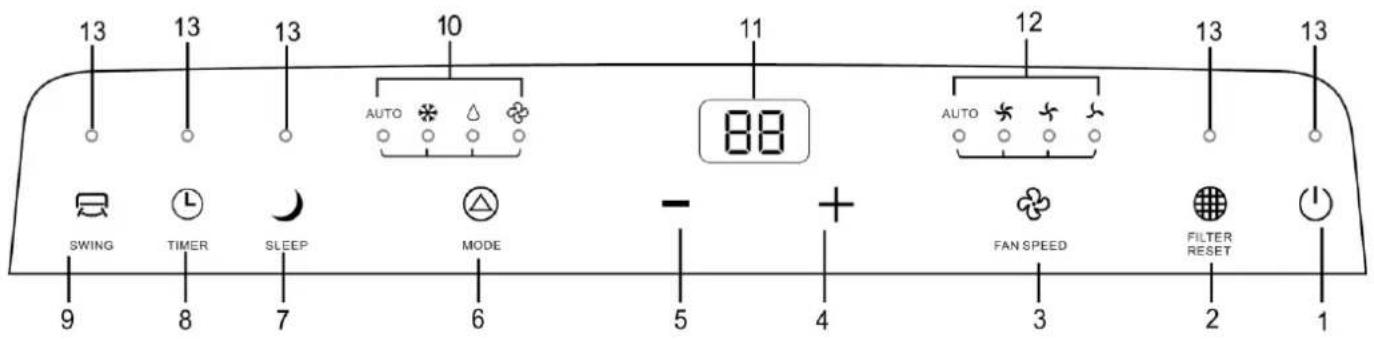
- ON/OFF button
2.Filter reset button - Fan speed button
- Up setting button
- Down setting button
6.Mode button - Sleep mode button
- Timer button
- Swing button
- LED lighting for select mode
- Temperature and time display
- Fan speed light indicator
- LED light
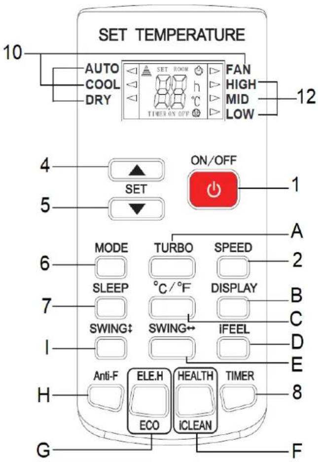
A. Turbo fan speed button
B. ON or OFF LCD display light button
C. ℃ or℉ temperature display button
D. IFEEL button
E. Louver horizontal swing button
F. Health ICLEAN button
G. ELE.H ECO button
H. ANTI-F button
I. Louver vertical * swing button
| Panneau | Télécommande | Description | |
| ON/OFF | Press one time on this ON/OFF button to switch on the appliance. | ||
| FILTERRESET | X | After 250 hours of use, this light function will illuminate to indicate that the filters need to be cleaned. Press this button once after cleaning the filters to reset the 250h cycle. Note: The light stays on until you press it again. | |
| + | ▲ | Up button for temperature or timer: * each pressure increases by 1 °C in cooling mode * each pressure increases the adjustment step of 30min or 1h This button does not work in ventilation and auto mode. | |
| - | ▼ | Down button for temperature or timer: * each pressure decreases by 1 °C in cooling mode * each pressure decreases the adjustment step of 30min or 1h This button does not work in ventilation and auto mode. | |
| MODE | Press on this button until the light of the selected mode illuminate: | ||
| COOL | Cooling mode: for setting the temperature between16°C and 32°C. Press up and down button to your desired setting. Press on the fan speed to select your desired fan speed. | ||
| AUTO | When you set the air conditioner in AUTO mode, it will automatically select cooling, or fan only operation depending on what temperature you have selected and the room temperature. The air conditioner will control room temperature automatically round the temperature point set by you. | ||
| FAN | Fan mode only. Press up and down button to your desired setting. The fan will run at the selected speed and the display will show the room temperature. | ||
| DRY | Dehumidifier mode: the temperature is set to 25°C and fan speed on low. Temperature and fan speed cannot be set on this mode. Keep doors and windows closed for best effect. | ||
| Note: the fan and the dry mode do not need the use of the exhaust hose. | |||
| SLEEP | SLEEP | Sleep mode: automatic program to save energy consumption with low fan speed in cooling mode. It will run for 8 hours then the unit will return to the initial setting. It can be cancelled at any time by pressing the button again. Note: This mode cannot be started for the fan mode or dehumidification function. | |
| SPEED | Fan speed button. Select different speed each time you press on it, the corresponding light indicator will turn on: | ||
| LOW | Slow speed | ||
| MID | Medium speed | ||
| HIGH | High speed | ||
| AUTO | Auto speed. Only for the cooling mode. | ||
| SWING↑ SWING← | Louvers auto swing mode: * on the control panel, press the button to allow the louvers to switch automatically. Press the button again until the louvers stop at the desired angle. * on the remote control, according to the desired oscillation, press the horizontal oscillation button or the vertical oscillation button. | ||
| X | TURBO | Button to auto select the high speed fan. | |
| X | °C/°F | The display shows the temperature in °C by default. Press this button to display the temperature in °F. Press this button again to return to the °C display. | |
| X | DISPLAY | This button turns off the illumination of the LCD screen while you sleep. | |
| X | iFEEL | Press this button to display the room temperature on the remote control; press this button again to display the set temperature. | |
| X | ELE.H ECO | Press button to enter power saving mode. This mode works for 8 hours. Note: This mode turns off when you switch modes or when the remote control is turned off. | |
| X | HEALTH iCLEAN | When the device is on, press this button to activate the "Health" function, which will release negative ions. Press again to exit this function. When the unit is off, press this button to activate the "iClean" function. The screen of the remote control displays CL. The unit automatically cleans the accumulated dust in the evaporator for 30 minutes. This function is disabled if you press this button again or the remote control is off. | |
| X | Anti-F | This button activates the internal drying function of the evaporator of the device. When the unit is off, press this button, the unit will operate for 3 minutes at low fan speed. It is not recommended to turn the unit on or to stop this function while it is being turned on. | |
| L | TIMER | Timer setting: You can set the delay stop time and delay start time when the unit is turned on or off. When the unit is turned on, press the timer button. The indicator light switches on and flashes. Press one UP or DOWN button to set the timer time between 30 minutes and 24 hours. Up to 10 hours, the time is adjustable in increments of half an hour. From 10 hours, it is in increments of one hour. Then press the timer button to confirm the setting. For delay strop time: Once the time is up, the unit turns off automatically. For delay start time: Once the countdown time has elapsed, the unit starts automatically in the selected mode. When the countdown time has elapsed, the unit starts automatically in the selected mode. You can change or cancel your setting by pressing this button again. If you do not need to set the delay start, press the TIMER button again to exit this setting. After 5 seconds, the setting will be automatically changed and the display will return to the previous temperature. If you want to check the remaining time, press the timer key. The delayed start automatically selects the fan mode, temperature, and speed, according to the settings you made last time. To activate the timer function when the unit is off, press the timer button to set the delay start time, then a second time to set the delay stop time, using the same procedure as above. | |
2. Remote control
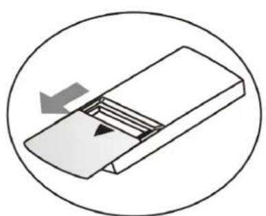
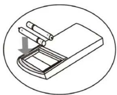
The remote control allows you to select your program away from your appliance. It works with 2 batteries type AAA/LR03 - 1.5V.
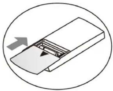
Inserting the batteries: Press the plastic flap cautiously at the back of the remote control and lift up the lid. Insert the 2 batteries according to the polarities shown inside the location. Close the plastic flap.
Note: Handle the remote control carefully. It should neither fall nor be exposed to sunlight or other heat source. Please note the ambient temperature is displayed on the control panel.
- To stop the appliance: press on the ON/OFF button.
- Unplug your appliance.
- Empty the water tank during long period of non-used.
The appliance has a safety compressor device. If the appliance turns itself off and does not switch itself on again, disconnect it from the mains supply, and wait for approximately 3 minutes before reconnecting.
WARNING: Unplug the appliance during cleaning. Do not put anything on the appliance, such as clothing or towels. Do not use the appliance in the bathroom or other wet areas.
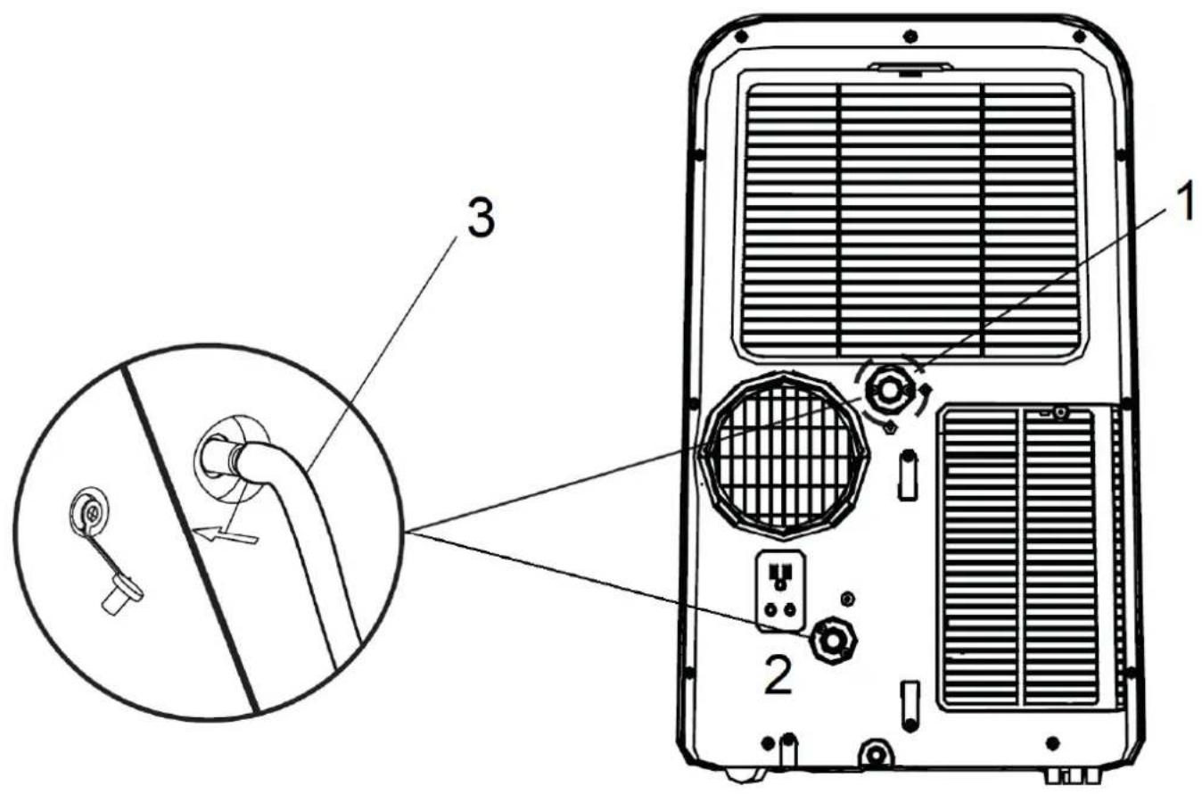
3. Dehumidifier mode and draining
In dehumidification mode, it is necessary to drain the condensate water from the unit. Remove the cap from the dehumidifier drain outlet (1), and then screw the hose to the fitting hole (3) as shown in the drawing.
The drain hose can then drain the water to a drain point.
You can also use the second drain outlet (2) and proceed in the same way.
Make sure you secure the hose to the fitting hole to prevent water leakage.
CLEANING AND MAINTENANCE
- The appliance needs only an external regular cleaning, the recommended cleaning frequency is every 15 days when used daily.
- Unplug the appliance.
- Do not immerse the appliance.
- When cleaning the outer part of the appliance, use a dry soft cloth (or sponge) or a damped one with neutral cleaner. Do not use a hard brush or any others cleaners to avoid scratching the appliance.
WARNING: Unplug the appliance during cleaning. For safety reasons never pour water on your appliance for cleaning. Do not use toxic and corrosive products such as alcohol, industrial cleaners, solvents to clean the appliance as these may damage it.
Water draining operation:
Your appliance is equipped with the Auto Evaporative System, it will automatically evaporates the condensation through the air outlet hose. There is no need to empty the bottom drainage tank except for the 3 below conditions:
- Exceptional climate with very high humidity conditions: the water tank fills up faster than the Auto evaporative system is capable of evacuating the condensation water. The icon "P1" will flash on the LCD control panel warning you to drain the tank.
- At the end of each seasonal use and in order to extend the life of your appliance. It is recommended after the water draining operation to fully dry the unit by operating in low fan mode for 4 hours before putting it in its storage space.
- When the appliance has not been used for a long period.
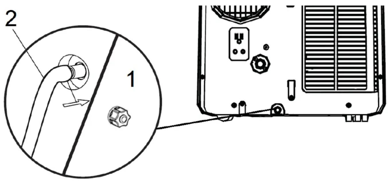
Water draining operation:
Unplug your appliance.
Place a pan under the water plug.
Unscrew the cap (1) then pull out the water plug and let the water drain. You can also use the drain hose to fix to the hole for draining (2)
After the operation, replace the water plug firmly.
Filter cleaning:
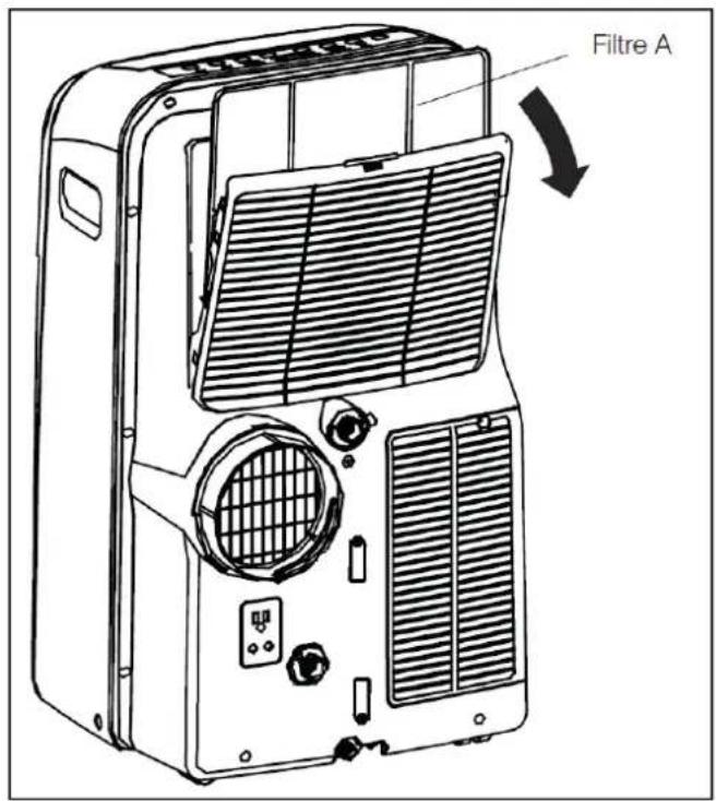
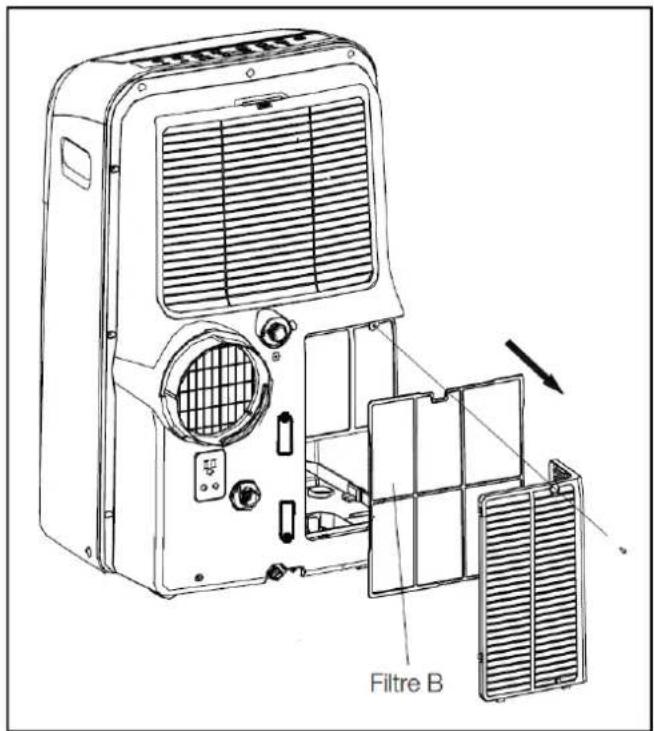
To prevent clogging of the internal components of the appliance, it is recommended to clean every 2 weeks the air filter located at the back of the device. This appliance has 2 kind of filters, A and B.
- Take out the air filter from its location by pulling it as shown on the drawing. Lift the tab on the top panel and remove the filter A located behind the grid on the back panel. Remove the bottom filter B by removing the screw from the bottom panel. Remove the air intake grid and remove the air filter.
✓ Use a vacuum cleaner to take out the dust before washing the air filter into warm water filled with dishwashing liquid. Rinse filter thoroughly. Gently shake excess water from the filter.
Dry the filter before putting it back on the appliance.
Note: Never use hot soapy water more than 40^ to clean your filter. Never bend your filter to avoid damaging it.
Postseason storage:
When the air conditioner is out of season or not used for long time, corresponding maintenance measures should be taken.
- Drain all water in water pan from outlet (water can be poured out by slowly leaning the body backward during drainage), and adjust operating mode to FAN mode, and then anti F button till fan works, keep this operating mode. This method can dry inside of the body and prevent mildew.
- Turn off the air conditioner and pull out power plug.
- Wind up, fasten and put away power line.
- Remove exhaust pipe and keep properly.
- Set the air conditioner into plastic bag and put it in a dry place.
- Take out of cells of remote control and keep properly.
TROUBLESHOOTING
| Issues | Possible causes | Solutions |
| The unit is not working | 1: the unit is unplugged2: No electricity3: 3 min. timing in progress4: The selected temperature is closed to the room temperature5: The room temperature is below 16°C6: the fuse is broken | 1: Plug the unit2: Check for power3: Wait for 3 min.4: Select a bigger temperature gap5: Stop using the air con6. Contact your after sales service |
| Bad performance | 1: The air filter is too dirty2: The air inlet and outlet grid are clogged by walls or objects3: Wrong programming | 1: Clean the air filter2: Remove the objects or change the unit location3: Switch of the appliance and restart the setting |
| The unit is too noisy | 1: The unit is not placed on a stable and flat surface2: The air filter is damaged | 1: Place the unit on a stable and flat surface2: Change the air filter |
| The remote control is not working | 1: Remote control and the unit is too far away2: Batteries are off | 1: Get closer to the unit2: Change the batteries |
| E1 on LCD display | Room temperature sensor issues | Switch off the appliance and switch on after 5 minutes. If it still not working, contact your after sales service. |
| E2 on LCD display | Evaporator temperature sensor issues | Switch off the appliance and switch on after 5 minutes. If it still not working, contact your after sales service. |
| E3 on LCD display | Condenser sensor issues | |
| E4 on LCD display | Display panel issue | Contact your after sales service. |
| P1 on LCD display | Water tank is full | Start the water draining operation |
Caution: when the following abnormalities occur to the air conditioner, shut down and pull out the plug, and then contact the manufacturer, its after sales service or a similar qualified technician:
- Fuse and switch are often broken.
- Power line is overheating or its coat is naked.
- The body produces abnormal odour.
TECHNICAL INFORMATION
| Model | TECHCLIM9 |
| Power supply | 220-240V ~ 50Hz |
| Electric shock prevention | Classe I |
| Climates type | T1 |
| Cooling capacity (Prated) | 2.6kW |
| Power input (PEER) | 0.87kW |
| MAX. input current | 4.6A |
| MAX. input power | 0.97kW |
| Rated energy efficiency ratio (EERrated) | 3.1 |
| Power consumption in standby mode (PsB) | 0.378 W |
| Electricity consumption of single duct appliances (QSD) | 0.864 kW/h |
| Air flow volume | 350m3/h |
| Noise level (LWA) | ≤ 64 dB(A) |
| GWP | 3.3 kg eq CO2 |
| Classe d'efficacité énergétique (A+++......D, A+++=économique D=moins économique) | A+ |
| Cooling capacity | 9000Btu/h |
| Maximum discharge pressure | 2.4Mpa |
| Maximum suction pressure | 1.0MPa |
| Net weight | 32.5 KG |
| Refrigerant / Quantity | R290 / 200g |
THIS PRODUCT CONTAINS FLAMMABLE GASES. THE FLAMMABLE GASES ARE CONTAINED IN HERMETICALLY SEALD EQUIPMENT.
SERVICING AND REPAIRING INSTRUCTION
Please follow the safety instructions when handling and repairing the device containing R290 flammable refrigerant.
Checks to the area
Prior to beginning work on systems containing flammable refrigerants, safety checks are necessary to ensure that the risk of ignition is minimised. For repair to the refrigerating system, the following precaution shall be completed prior to conducting work on the system.
Work procedure
Work shall be undertaken under a controlled procedure so as to minimise the risk of a flammable gas or vapour being present while the work is being performed.
General work area
All maintenance staff and others working in the local area shall be instructed on the nature of work being carried out. Work in confined spaces shall be avoided.
Checking for presence of refrigerant
The area shall be checked with an appropriate refrigerant detector prior to and during work, to ensure the technician is aware of potentially toxic or flammable atmospheres. Ensure that the leak detection equipment being used is suitable for use with all applicable refrigerants, i.e. non-sparking, adequately sealed or intrinsically safe.
Presence of fire extinguisher
If any hot work is to be conducted on the refrigerating equipment or any associated parts, appropriate fire extinguishing equipment shall be available to hand. Have a dry powder or CO2 fire extinguisher adjacent to the charging area.
No ignition sources
No person carrying out work in relation to a refrigerating system which involves exposing any pipe work shall use any sources of ignition in such a manner that it may lead to the risk of fire or explosion. All possible ignition sources, including cigarette smoking, should be kept sufficiently far away from the site of installation, repairing, removing and disposal, during which refrigerant can possibly be released to the surrounding space. Prior to work taking place, the area around the equipment is to be surveyed to make sure that there are no flammable hazards or ignition risks. "No Smoking" signs shall be displayed.
Ventilated area
Ensure that the area is in the open or that it is adequately ventilated before breaking into the system or conducting any hot work. A degree of ventilation shall continue during the period that the work is carried out. The ventilation should safely disperse any released refrigerant and preferably expel it externally into the atmosphere.
Checks to the refrigerating equipment
Where electrical components are being changed, they shall be fit for the purpose and to the correct specification. At all times the manufacturer's maintenance and service guidelines shall be followed. If in doubt, consult the manufacturer's technical department for assistance.
The following checks shall be applied to installations using flammable refrigerants:
- the actual refrigerant charge is in accordance with the room size within which the refrigerant containing parts are installed;
- the ventilation machinery and outlets are operating adequately and are not obstructed;
- if an indirect refrigerating circuit is being used, the secondary circuit shall be checked for the presence of refrigerant; marking to the equipment continues to be visible and legible. Markings and signs that are illegible shall be corrected;
- refrigerating pipe or components are installed in a position where they are unlikely to be exposed to any substance which may corrode refrigerant containing components, unless the components are constructed of materials which are inherently resistant to being corroded or are suitably protected against being so corroded.
Checks to electrical devices
Repair and maintenance to electrical components shall include initial safety checks and component inspection procedures. If a fault exists that could compromise safety, then no electrical supply shall be connected to the circuit until it is satisfactorily dealt with. If the fault cannot be corrected immediately but it is necessary to continue operation, an adequate temporary solution shall be used. This shall be reported to the owner of the equipment so all parties are advised.
Initial safety checks shall include:
- that capacitors are discharged: this shall be done in a safe manner to avoid possibility of sparking;
- that no live electrical components and wiring are exposed while charging, recovering or purging the system;
- that there is continuity of earth bonding.
Repairs to sealed components
During repairs to sealed components, all electrical supplies shall be disconnected from the equipment being worked upon prior to any removal of sealed covers, etc. If it is absolutely necessary to have an electrical supply to equipment during servicing, then a permanently operating form of leak detection shall be located at the most critical point to warn of a potentially hazardous situation.
Particular attention shall be paid to the following to ensure that by working on electrical components, the casing is not altered in such a way that the level of protection is affected. This shall include damage to cables, excessive number of connections, terminals not made to original specification, damage to seals, incorrect fitting of glands, etc.
Ensure that the apparatus is mounted securely.
Ensure that seals or sealing materials have not degraded to the point that they no longer serve the purpose of preventing the ingress of flammable atmospheres. Replacement parts shall be in accordance with the manufacturer's specifications.
Repair to intrinsically safe components
Do not apply any permanent inductive or capacitance loads to the circuit without ensuring that this will not exceed the permissible voltage and current permitted for the equipment in use.
Intrinsically safe components are the only types that can be worked on while live in the presence of a flammable atmosphere. The test apparatus shall be at the correct rating.
Replace components only with parts specified by the manufacturer. Other parts may result in the ignition of refrigerant in the atmosphere from a leak.
Cabling
Check that cabling will not be subject to wear, corrosion, excessive pressure, vibration, sharp edges or any other adverse environmental effects. The check shall also take into account the effects of aging or continual vibration from sources such as compressors or fans.
Detection of flammable refrigerants
Under no circumstances shall potential sources of ignition be used in the searching for or detection of refrigerant leaks. A halide torch (or any other detector using a naked flame) shall not be used.
Removal and evacuation
When breaking into the refrigerant circuit to make repairs – or for any other purpose – conventional procedures shall be used. However, for flammable refrigerants it is important that best practice is followed since flammability is a consideration. The following procedure shall be adhered to:
- remove refrigerant;
purge the circuit with inert gas; - evacuate;
purge with inert gas; - open the circuit by cutting or brazing.
The refrigerant charge shall be recovered into the correct recovery cylinders. For appliances containing flammable refrigerants the system shall be purged with oxygen-free nitrogen to render the appliance safe for flammable refrigerants. This process may need to be repeated several times. Compressed air or oxygen shall not be used for purging refrigerant systems.
For appliances containing flammable refrigerants, refrigerants purging shall be achieved by breaking the vacuum in the system with oxygen-free nitrogen and continuing to fill until the working pressure is achieved, then venting to atmosphere, and finally pulling down to a vacuum. This process shall be repeated until no refrigerant is within the
system. When the final oxygen-free nitrogen charge is used, the system shall be vented down to atmospheric pressure to enable work to take place. This operation is absolutely vital if brazing operations on the pipe-work are to take place. Ensure that the outlet for the vacuum pump is not close to any potential ignition sources and that ventilation is available.
Charging procedures
In addition to conventional charging procedures, the following requirements shall be followed.
- Ensure that contamination of different refrigerants does not occur when using charging equipment. Hoses or lines shall be as short as possible to minimise the amount of refrigerant contained in them.
- Cylinders shall be kept in an appropriate position according to the instructions.
- Ensure that the refrigerating system is earthed prior to charging the system with refrigerant.
- Label the system when charging is complete (if not already).
- Extreme care shall be taken not to overfill the refrigerating system.
Prior to recharging the system, it shall be pressure-tested with the appropriate purging gas. The system shall be leak-tested on completion of charging but prior to commissioning. A follow up leak test shall be carried out prior to leaving the site.
Decommissioning
Before carrying out this procedure, it is essential that the technician is completely familiar with the equipment and all its detail. It is recommended good practice that all refrigerants are recovered safely. Prior to the task being carried out, an oil and refrigerant sample shall be taken in case analysis is required prior to re-use of recovered refrigerant. It is essential that electrical power is available before the task is commenced.
a) Become familiar with the equipment and its operation.
b) Isolate system electrically.
c) Before attempting the procedure, ensure that:
- mechanical handling equipment is available, if required, for handling refrigerant cylinders;
- all personal protective equipment is available and being used correctly;
- the recovery process is supervised at all times by a competent person;
- recovery equipment and cylinders conform to the appropriate standards.
d) Pump down refrigerant system, if possible.
e) If a vacuum is not possible, make a manifold so that refrigerant can be removed from various parts of the system.
f) Make sure that cylinder is situated on the scales before recovery takes place.
g) Start the recovery machine and operate in accordance with instructions.
h) Do not overfill cylinders (no more than 80% volume liquid charge).
i) Do not exceed the maximum working pressure of the cylinder, even temporarily.
j) When the cylinders have been filled correctly and the process completed, make sure that the cylinders and the equipment are removed from site promptly and all isolation valves on the equipment are closed off.
k) Recovered refrigerant shall not be charged into another refrigerating system unless it has been cleaned and checked.
Labelling
Equipment shall be labelled stating that it has been de-commissioned and emptied of refrigerant. The label shall be dated and signed. For appliances containing flammable refrigerants, ensure that there are labels on the equipment stating the equipment contains flammable refrigerant.
Recovery
When removing refrigerant from a system, either for servicing or decommissioning, it is recommended good practice that all refrigerants are removed safely.
When transferring refrigerant into cylinders, ensure that only appropriate refrigerant recovery cylinders are employed. Ensure that the correct number of cylinders for holding the total system charge is available. All cylinders to be used are designated for the recovered refrigerant and labelled for that refrigerant (i.e. special cylinders for the recovery of refrigerant). Cylinders shall be complete with pressure-relief valve and associated shut-off valves in good working order. Empty recovery cylinders are evacuated and, if possible, cooled before recovery occurs.
The recovery equipment shall be in good working order with a set of instructions concerning the equipment that is at hand and shall be suitable for the recovery of all appropriate refrigerants including, when applicable, flammable refrigerants. In addition, a set of calibrated weighing scales shall be available and in good working order. Hoses shall be complete with leak-free disconnect couplings and in good condition. Before using the recovery machine, check that
it is in satisfactory working order, has been properly maintained and that any associated electrical components are sealed to prevent ignition in the event of a refrigerant release. Consult manufacturer if in doubt.
The recovered refrigerant shall be returned to the refrigerant supplier in the correct recovery cylinder, and the relevant waste transfer note arranged. Do not mix refrigerants in recovery units and especially not in cylinders..
If compressors or compressor oils are to be removed, ensure that they have been evacuated to an acceptable level to make certain that flammable refrigerant does not remain within the lubricant. The evacuation process shall be carried out prior to returning the compressor to the suppliers. Only electric heating to the compressor body shall be employed to accelerate this process. When oil is drained from a system, it shall be carried out safely.

Vestel France, 17 rue de la Couture - 94563 Rungis CEDEX
This manual instruction is also available on the following website: http://pieces-detachees.sogedis.fr/

- Attention
- SAFETY CAUTIONS
- STANDARDS
- TABLE OF CONTENTS
- DESCRIPTION
- SET-UP AND USE
- Installation
- Using your appliance
- Electronic control panel and remote control
- Remote control
- Dehumidifier mode and draining
- CLEANING AND MAINTENANCE
- Water draining operation:
- Filter cleaning:
- Postseason storage:
- TROUBLESHOOTING
- TECHNICAL INFORMATION
- SERVICING AND REPAIRING INSTRUCTION
- Checks to the area
- Work procedure
- General work area
- Checking for presence of refrigerant
- Presence of fire extinguisher
- No ignition sources
- Ventilated area
- Checks to the refrigerating equipment
- Checks to electrical devices
- Repairs to sealed components
- Repair to intrinsically safe components
- Cabling
- Detection of flammable refrigerants
- Removal and evacuation
- Charging procedures
- Decommissioning
- Labelling
- Recovery
Brand : TELEFUNKEN
Model : TECHCLIM9
Category : Air Conditioning