
702 S2 - Speaker BOWERS & WILKINS - Free user manual and instructions
Find the device manual for free 702 S2 BOWERS & WILKINS in PDF.
| Brand | Bowers & Wilkins |
| Model | 702 S2 |
| Product type | Floor-standing 3-way speaker |
| Dimensions (H x W x D) | Approx. 103.6 cm x 20 cm x 33.8 cm |
| Weight | 29.5 kg (without accessories) |
| Power | Passive, unpowered |
| Nominal impedance | 8 ohms (minimum 3.1 ohms) |
| Sensitivity | 90 dB SPL (2.83 V/1 m) |
| Frequency response | 28 Hz – 30 kHz (-6 dB) |
| Crossover frequencies | 300 Hz, 4 kHz |
| Connectors | Double binding posts (bi-wiring possible) |
| Included accessories | 4 M6 spikes, 4 nuts, 4 rubber feet, 1 base plate, 1 Allen key, 2 foam bungs, 1 floor stand |
| Main features | Carbon dome tweeter, Continuum midrange cone, dual Aerofoil bass cones, bass adjustment via foam bungs |
| Care and cleaning | Gentle dusting, avoid abrasive products, use unscented soapy water |
| Safety | Keep at least 50 cm away from CRT screens, magnetic cards, etc. |
| Spare parts and repairability | Spikes, nuts, rubber feet, foam bungs available; base plate and drivers not detailed as spare parts |
| General information | Compliant with RoHS, REACH, WEEE directives; break-in period of about 15 hours |
Frequently Asked Questions - 702 S2 BOWERS & WILKINS
User questions about 702 S2 BOWERS & WILKINS
0 question about this device. Answer the ones you know or ask your own.
Ask a new question about this device
Download the instructions for your Speaker in PDF format for free! Find your manual 702 S2 - BOWERS & WILKINS and take your electronic device back in hand. On this page are published all the documents necessary for the use of your device. 702 S2 by BOWERS & WILKINS.
USER MANUAL 702 S2 BOWERS & WILKINS
Welcome and thank you for choosing Bowers & Wilkins.
Our founder, John Bowers, believed that imaginative design, innovative engineering and advanced technology were keys that could unlock the enjoyment of audio in the home. His belief is one that we continue to share and inspires every product we design.
This is a high performance product that rewards thoughtful installation, so we suggest that you take some time to read this manual before you begin. Continue on page 5 →


natural_image
Product display of four different electronic devices (no visible text or labels)- Unpacking
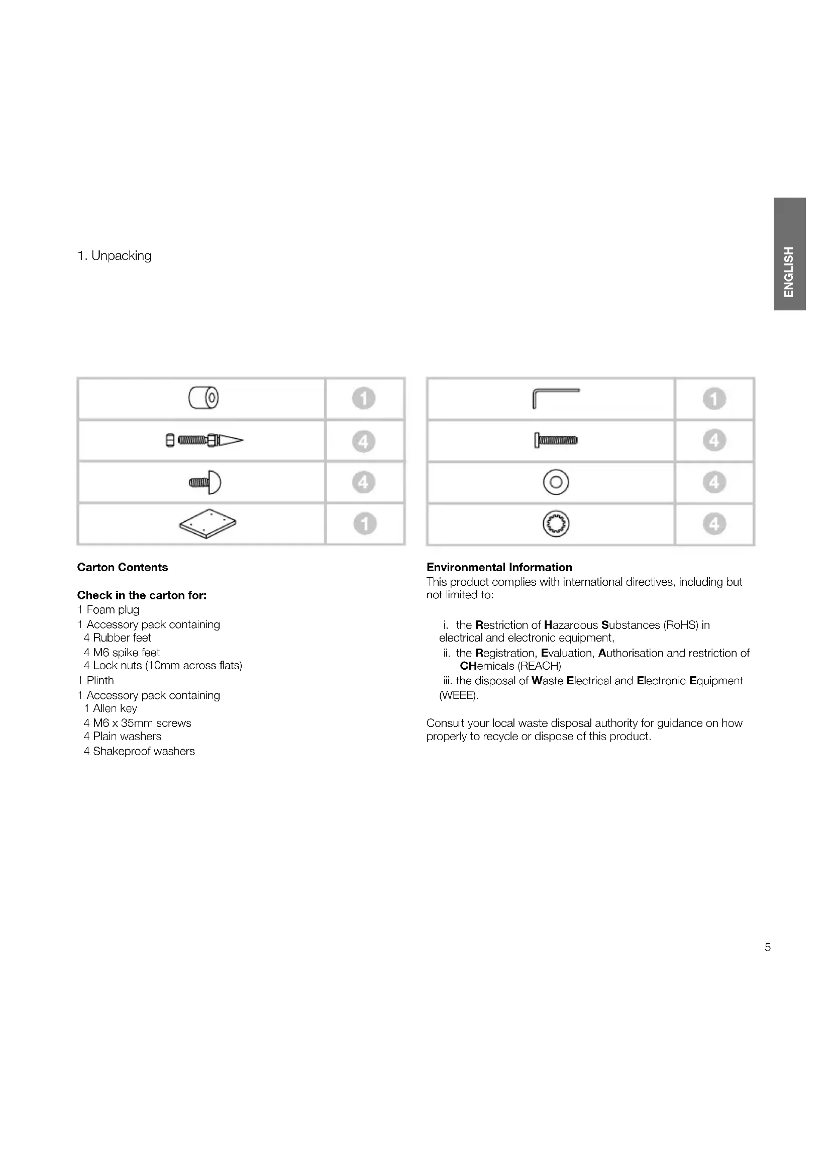
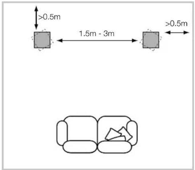
Carton Contents
Check in the carton for:
1 Foam plug
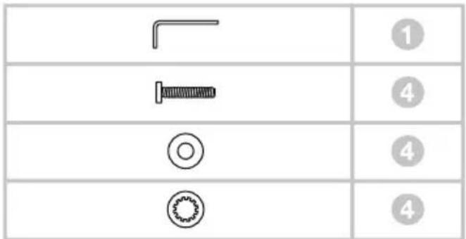
1 Accessory pack containing
4 Rubber feet
4 M6 spike feet
4 Lock nuts (10mm across flats)
1 Plinth
1 Accessory pack containing
1 Allen key
4 M6 x 35mm screws
4 Plain washers
4 Shakeproof washers
| 1 | |
| 4 | |
| 4 | |
| 4 |
Environmental Information
This product complies with international directives, including but not limited to:
i. the Restriction of Hazardous Substances (RoHS) in electrical and electronic equipment,
ii. the Registration, Evaluation, Authorisation and restriction of CHemicals (REACH)
iii. the disposal of Waste Electrical and Electronic Equipment (WEEE).
Consult your local waste disposal authority for guidance on how properly to recycle or dispose of this product.
- Positioning
natural_image
Technical line drawing of a mechanical assembly with mounting brackets and alignment indicators (no text or symbols)Speaker Installation
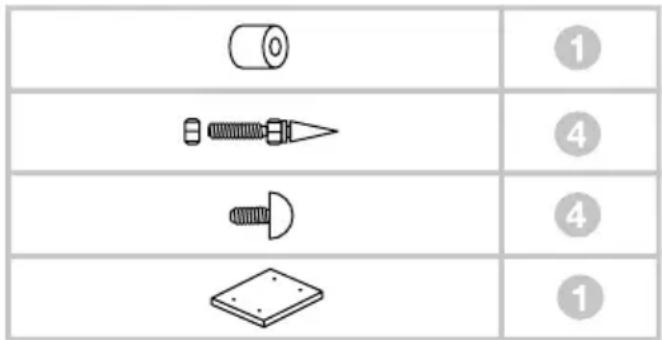
The speakers are intended to be floor mounted only. It is important to ensure that the speakers stand firmly on the floor using the spike feet supplied whenever possible. In addition, fit the plinth for proper stability.
You may attach the plinth during the unpacking process, following the diagrams on the top flap of the carton. Alternatively, you may attach it after the product has been fully unpacked, by covering a suitable support such as a table with a cloth and laying the speaker on its side with the base of the cabinet overhanging the support. Align the plinth with its attachment holes in the underside of the cabinet, ensuring that the arrow on the underside of the plinth points forwards. Secure the plinth using the screws and washers supplied. Fit the shakeproof washers between the plain washers and the screw heads. Tighten the screws using the Allen key supplied.
The spike feet are designed to pierce carpet and rest on the floor surface. Initially, screw the lock nuts onto the spikes enough to leave the nuts floating just above the carpet when the spikes are resting on the floor beneath. Screw the spikes fully into the threaded inserts in the plinth. If the cabinet rocks when placed on the floor, unscrew the two spikes that do not touch the floor until the cabinet rests firmly without rocking. Finally, lock the nuts against the cabinet. It may be more convenient to fit and adjust the spike feet after speaker positioning has been optimised.
If there is no carpet and you wish to avoid scratching the floor surface, use either a protective metal disc (a coin perhaps) between the spike and the floor, or use the supplied rubber feet. Fit the rubber feet and level the cabinet in the same manner as with the spike feet.
Speaker Positioning
Adjustment of speaker position following initial installation will probably further improve the sound quality and is usually worthwhile.
In either stereo or home theatre installations, try to ensure that the immediate surroundings of each speaker are similar in acoustic character. For example, if one speaker is adjacent to bare walls while the other is adjacent to soft furnishings and curtains, both the overall sound quality and the stereo image are likely to be compromised.
Conventional Stereo Systems
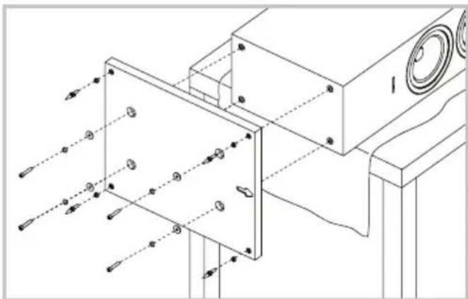
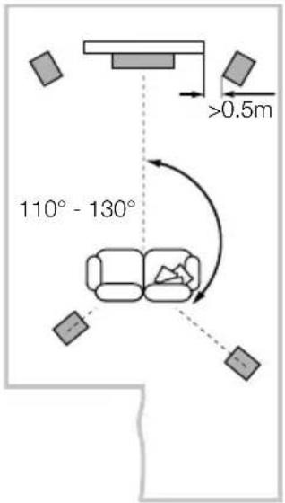
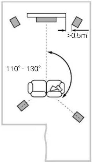
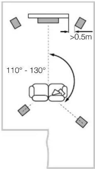
To begin with, the speakers should be positioned between 1.5m and 3m apart at two corners of an equilateral triangle completed by the listening area at the third corner. The speakers should be approximately 0.5m away from the back wall, and at least 0.5m away from any side walls (above).
5 Channels 7 Channels
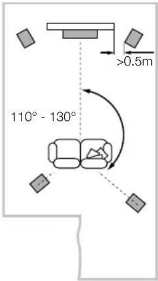
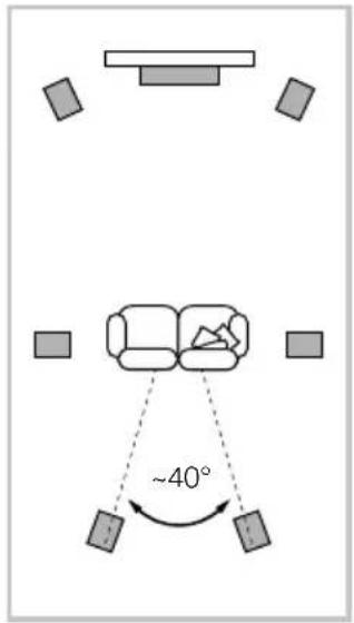
Home Theatre Systems
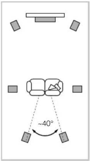
If the speakers are to be used for the front channels in a home theatre system, they should be placed closer together than for 2-channel audio, because the surround channels tend to widen the image. Positioning the speakers within approximately 0.5m of the sides of the screen will also help keep the sound image in scale with the visual image. As with conventional stereo positioning, the speakers should ideally be at least 0.5m away from any side walls. If you would prefer to place your speaker against the back wall and this location results in over emphasised bass, see the Fine Tuning section of this manual for information on using the foam plugs.
Stray magnetic fields
The speaker drive units create stray magnetic fields that extend beyond the boundaries of the cabinet. We recommend you keep magnetically sensitive articles (CRT television and computer screens, computer discs, audio and video tapes, swipe cards and the like) at least 0.5m from the speaker. LCD, OLED and plasma screens are not affected by magnetic fields.
3. Connections
natural_image
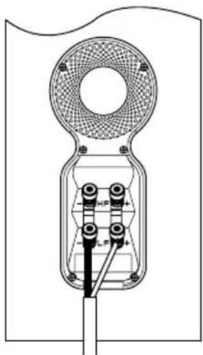
Technical line drawing of a mechanical device with a circular top and internal components (no text or symbols)All connections should be made with the audio equipment switched off.
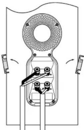
There are 2 linked pairs of terminals on the back of the speaker. For conventional connection (above left), the terminal links should remain in place (as delivered) and just one pair of terminals connected to the amplifier. For bi-wire connections or bi-amplification (above right), the terminal links should be removed and each pair of terminals connected to the amplifier or amplifiers independently. Bi-wiring can improve the resolution of low-level detail.
natural_image
Technical line drawing of a mechanical device with rotating components and mounting brackets (no text or symbols)Ensure that the positive terminals on the speaker (marked + and coloured red) are connected to the positive output terminal on the amplifier and the negative terminals on the speaker (marked - and coloured black) are connected to the negative output terminal on the amplifier. Incorrect connection can result in poor imaging and loss of bass.
Ask your dealer for advice when selecting speaker cable.
- Fine Tuning
Before fine tuning, make sure that all the connections in the installation are correct and secure.
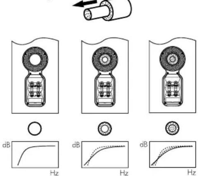
Moving the speakers further from the walls will generally reduce the volume of bass. Space behind the speakers will also help to create an aural impression of depth. Conversely, moving the speakers closer to the walls will increase the volume of bass. If you want to reduce the volume of bass without moving the speakers further from the wall, fit the foam plugs or, for less severe bass reduction, the foam rings in the port tubes (above).
If the bass seems uneven with frequency this will most probably be a consequence of the acoustic properties of your listening room. Even small changes in the position of the speakers or listening position can have a significant effect on sonic performance, especially at low frequencies. Try moving your listening position or locating your speakers along a different wall if possible.
If no alternatives exist, you can adjust your loudspeakers' low-frequency performance using the supplied foam bungs. The bungs are a two-piece part, allowing for a degree of fine-tuning using either the outer, larger-diameter piece in isolation or the two parts together. Using solely the outer, larger-diameter foam bung will deliver less bass attenuation than the complete bung assembly.
- Running In 6. Aftercare
The performance of the speaker will change subtly during the initial listening period. If the speaker has been stored in a cold environment, the damping compounds and suspension materials of the drive units will take some time to recover their correct mechanical properties. The drive unit suspensions will also loosen up during the first hours of use. The time taken for the speaker to achieve its intended performance will vary depending on previous storage conditions and how it is used. As a guide, allow up to a week for the temperature effects to stabilise and 15 hours of average use for the mechanical parts to attain their intended design characteristics.
The cabinet surfaces will usually only require dusting. If you wish to use an aerosol or other cleaner, apply the cleaner onto the cloth, not directly onto the product and test a small area first, as some cleaning products may damage some of the surfaces. Avoid products that are abrasive, or contain acid, alkali or antibacterial agents. Marks on the paint surface may be removed with a dilute perfume-free soap solution. Remove any remaining streak marks by spraying with a proprietary glass cleaner and lightly wiping dry with a microfibre cloth. Do not use cleaning agents on the drive units and avoid touching them as damage may result.
Real wood veneers are treated with an ultra-violet resistant lacquer to minimise changes in colour over time. Nevertheless, like all natural materials, a degree of colour change is to be expected. Colour differences may be rectified by exposing all the veneer surfaces equally and evenly to sunlight until the colour is uniform. This process can take a long time, but may be accelerated by careful use of an ultra-violet lamp. Keep the speakers away from direct sources of heat such as radiators and warm air vents in order to minimise the possibility of the wood veneer cracking.
- Déballage

natural_image
Technical line drawing of a mechanical assembly with mounting brackets and alignment indicators (no text or symbols)5 Channels 7 Channels


natural_image
Technical line drawing of a mechanical device with a circular top and internal components (no text or symbols)natural_image
Pure mechanical diagram of a device with no text, numbers, or symbolsKartoninhalt
Im Karton liegen:
natural_image
Technical line drawing of a mechanical assembly with mounting brackets and alignment indicators (no text or symbols)5 Channels 7 Channels


Heimkinosysteme
natural_image
Technical line drawing of a mechanical device with a circular top and internal components (no text or symbols)natural_image
Technical line drawing of a mechanical device with rotating components and mounting brackets (no text or symbols)natural_image
Technical line drawing of a mechanical assembly with mounting brackets and alignment indicators (no text or symbols)5 Channels 7 Channels

natural_image
Technical diagram of a mechanical device with labeled components and mounting holes (no text or symbols present)natural_image
Pure mechanical diagram of a pulley or switch mechanism without any text, numbers, or symbolsConteúdos da caixa
natural_image
Technical line drawing of a mechanical assembly with mounting brackets and alignment indicators (no text or symbols)natural_image
Technical diagram of a mechanical device with labeled components and mounting holes (no text or symbols present)natural_image
Pure mechanical diagram of a pulley or switch mechanism without any text, numbers, or symbolsnatural_image
Technical line drawing of a mechanical assembly with mounting brackets and alignment indicators (no text or symbols)Installazione
Posizionamento

Sistemi Home Theatre
natural_image
Technical line drawing of a mechanical device with a circular top and internal components (no text or symbols)natural_image
Pure mechanical diagram of a pulley or switch mechanism without any text, numbers, or symbolsInhoud doos
natural_image
Technical line drawing of a mechanical assembly with mounting brackets and alignment indicators (no text or symbols)Luidspreker Installeren
Luidsprekeropstelling
5 Channels 7 Channels


Home Theater Systemen
natural_image
Technical line drawing of a mechanical device with internal components and mounting holes (no text or symbols)natural_image
Pure mechanical diagram of a pulley or switch mechanism without any text, numbers, or symbolsnatural_image
Technical line drawing of a mechanical assembly with mounting brackets and alignment indicators (no text or symbols)Τοποθέτηση ηχείου
natural_image
Technical line drawing of a mechanical device with a circular top and internal components (no text or symbols)natural_image
Technical line drawing of a mechanical device with rotating components and mounting brackets (no text or symbols)Содержание упаковки
natural_image
Technical line drawing of a mechanical assembly with no visible text or symbolsУстановка колонок
5 Channels 7 Channels

natural_image
Technical line drawing of a mechanical device with a circular top and internal components (no text or symbols)natural_image
Pure mechanical diagram of a pulley or switch mechanism without any text, numbers, or symbolsObsah balení
natural_image
Technical line drawing of a mechanical assembly with mounting brackets and alignment indicators (no text or symbols)Pozice reprosoustav

Domácí kino
natural_image
Technical line drawing of a mechanical device with a circular top and internal components (no text or symbols)natural_image
Technical line drawing of a mechanical device with rotating components and mounting brackets (no text or symbols)natural_image
Technical line drawing of a mechanical assembly with mounting brackets and alignment indicators (no text or symbols)
natural_image
Technical line drawing of a mechanical device with no visible text or symbolsnatural_image
Technical line drawing of a mechanical device with rotating components and mounting brackets (no text or symbols)natural_image
Technical line drawing of a mechanical assembly with mounting brackets and alignment indicators (no text or symbols)Instalacja głośnika
Ustawienie głośnika
5 Channels 7 Channels


natural_image
Technical line drawing of a mechanical device with a circular top and internal components (no text or symbols)natural_image
Pure mechanical diagram of a device with no text, numbers, or symbolsKarton Kutu İçeriği
natural_image
Technical line drawing of a mechanical assembly with mounting brackets and alignment indicators (no text or symbols)Hoparlör Kurulumu

Ev Sineması Sistemi
natural_image
Technical line drawing of a mechanical device with a circular top and internal components (no text or symbols)natural_image
Pure mechanical diagram of a device with no text, numbers, or symbols包装箱内的物品
检查纸箱内的下列物品:
环保信息
本产品符合国际指令,包括但不限于:
natural_image
Technical line drawing of a mechanical assembly with no visible text or symbols扬声器的安装
扬声器的定位
5 Channels 7 Channels

家庭影院系统
natural_image
Technical line drawing of a mechanical device with internal components and mounting holes (no text or symbols)所有的连接应当在设备关闭时进行。
natural_image
Pure mechanical diagram of a device with no text, numbers, or symbols包裝箱內的物品
檢查紙箱內的下列物品:
環保信息
本產品符合國際指令,包括但不限於:
natural_image
Technical line drawing of a mechanical assembly with no visible text or symbols揚聲器的安裝
揚聲器的定位
5 Channels 7 Channels

家庭影院系統
natural_image
Technical line drawing of a mechanical device with internal components and mounting holes (no text or symbols)所有的連接應當在設備關閉時進行。
natural_image
Pure mechanical diagram of a pulley or switch mechanism without any text, numbers, or symbols内容物
以下の内容を確認してください。
フォームプラグ 1個
アクセサリーパック1 袋
中身
ゴム足 4個
M6スパイク 4本
ロックナット(10mm平面幅)4個
台座 1個
アクセサリーパック 1袋
中身
六角レンチ 1個
M6 x 35mmネジ 4個
平ワッシャー 4個
菊座ワッシャー 4個
環境関連情報
natural_image
Technical line drawing of a mechanical assembly with no visible text or symbolsスピーカーの設置
スピーカー設置位置
natural_image
Technical line drawing of a mechanical device with internal components and mounting holes (no text or symbols)natural_image
Pure mechanical diagram of a device with no text, numbers, or symbols내용물
환경 정보
natural_image
Technical line drawing of a mechanical assembly with no visible text or symbols스피커 설치
스피커 설치 위치

홈씨어터 시스템
natural_image
Technical line drawing of a mechanical device with internal components and mounting holes (no text or symbols)natural_image
Pure mechanical diagram of a device with no text, numbers, or symbolsWorthing West Sussex
BN11 2BH England
T+44(0)1903221800
F +44 (0) 1903221801
info@bwgroup.com
www.bowers-wilkins.com
B&W Group (UK Sales)
T+44(0)1903221500
E uksales@bwgroup.com
B&W Group North America
T+19786642870
E marketing@bwgroupusa.com
B&W Group Asia Ltd
T+85234729300
E info@bwgroup.hk
Copyright © B&W Group Ltd. E&OE
Printed in China