USER MANUAL CWE23SP3MD1 GE
Owner's Manual and Installation Instructions
Bottom Freezer Refrigerators
Models that start with CFE are Standard Depth Models (SD)
Models that start with CYE and CWE are Counter Depth Models (CD)
Contents
Safety Information .... 3 Installation Instructions
Using the Refrigerator Preparing to Install the Refrigerator 23
Features ...... 16 Installing the Refrigerator ...... 25
Controls 8 Installing the Anti- Tip Bracket 31
Dispenser 1 1 Installing the Water Line 3 6
Hot Water ....Troubleshooting Tips ....37
Single Serve Keurig K-Cup Brewer 13 Normal Operating Conditions 39
Appliance Communication....14 Truth or Myth....4
Fresh Food Storage Options 15 Limited Warranty 44
Climate Zone & Temperature Limited Warranty
Controlled Drawer 17 Consumer Support
Freezer 1RPWFE Water Filter Cartridge
Automatic Ice maker ....Limited Warranty ....
Care And Cleaning 21 Performance Data Sheet 48 Consumer Support 48
Replacing the Lights 22 Consumer Support.
Write the model and serial numbers here:
Model # ____
Serial # ____
Find these numbers on a label on the left side, near the middle of the refrigerator compartment.
ENGLISH/FRANÇAIS/ESPAÑOL
THANK YOU FOR MAKING CAFÉ A PART OF YOUR HOME.
We take pride in the craftsmanship, innovation and design that goes into every Café product, and we think you will too. Among other things, registration of your appliance ensures that we can deliver important product information and warranty details when you need them.
Register your Café appliance now online. Helpful websites are available in the Consumer Support section of this Owner's Manual. You may also mail in the pre-printed registration card included in the packing material.
CAFÉ
WARNING
To reduce the risk of fire, explosion, electric shock, or injury when using your refrigerator, follow these basic safety precautions:
This refrigerator must be properly installed and located in accordance with the Installation Instructions before it is used.
■ Unplug the refrigerator before making repairs, replacing a light bulb, or cleaning.
NOTE: Power to the refrigerator cannot be disconnected by any setting on the control panel.
NOTE: Repairs must be performed by a qualified Service Professional.
■ Replace all parts and panels before operating.
■ Do not use an extension cord.
■ Do not store or use gasoline or other flammable vapors and liquids in the vicinity of this or any other appliance.
■ Do not store explosive substances such as aerosol cans with a flammable propellant in this appliance.
■ To prevent suffocation and entrapment hazards to children, remove the fresh food and freezer doors from any refrigerator before disposing of it or discontinuing its use.
■ To avoid serious injury or death, children should not stand on, or play in or with the appliance.
■ Children and persons with reduced physical, sensory or mental capabilities or lack of experience and knowledge can use this appliance only if they are supervised or have been given instructions on safe use and understand the hazards involved.
This appliance is intended to be used in household and similar applications such as: staff kitchen areas in shops, offices and other working environments; farm houses; by clients in hotels, motels, bed & breakfast and other residential environments; catering and similar non-retail applications.
STATE OF CALIFORNIA PROPOSITION 65 WARNINGS:
WARNING
This product contains one or more chemicals known to the State of California to cause cancer and birth defects or other reproductive harm.
CAUTION
To reduce the risk of injury when using your refrigerator, follow these basic safety precautions.
■ Do not clean glass shelves or covers with warm water when they are cold. Glass shelves and covers may break if exposed to sudden temperature changes or impact, such as bumping or dropping. Tempered glass is designed to shatter into many small pieces if it breaks.
- Keep fingers out of the “pinch point” areas; clearances between the doors and between the doors and cabinet are necessarily small. Be careful closing doors when children are in the area.
■ Do not refreeze frozen foods which have thawed completely.
In refrigerators with automatic icemakers, avoid contact with the moving parts of the ejector mechanism, or with the heating element that releases the cubes. Do not place fingers or hands on the automatic ice making mechanism while the refrigerator is plugged in.
INSTALLATION
WARNING

PLOSION HAZARD
Keep flammable materials and vapors, such as gasoline, away from refrigerator. Failure to do so can result in fire, explosion, or death.
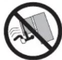
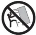
WARNING
VER HAZARD.
Built-in style models (models CYE and CWE) are top heavy, especially with any doors open. These models must be secured with the anti-tip floor bracket to prevent tipping forward, which could result in death or serious injury. Read and follow the entire installation instructions for installing the anti-tip floor bracket packed with your refrigerator.
READ AND SAVE THESE INSTRUCTIONS
CONNECTING ELECTRICITY
WARNING

LECTRICAL SHOCK HAZARD
Plug into a grounded 3-prong outlet
Do not remove the ground prong
Do not use an adapter
Do not use an extension cord.
Failure to follow these instructions can result in death, fire, or electrical shock.
Do not, under any circumstances, cut or remove the third (ground) prong from the power cord. For personal safety, this appliance must be properly grounded.
The power cord of this appliance is equipped with a 3-prong (grounding) plug which mates with a standard 3-prong (grounding) wall outlet to minimize the possibility of electric shock hazard from this appliance.
Have the wall outlet and circuit checked by a qualified electrician to make sure the outlet is properly grounded.
Where a standard 2-prong wall outlet is encountered, it is your personal responsibility and obligation to have it replaced with a properly grounded 3-prong wall outlet. Do not use an adapter.
The refrigerator should always be plugged into its own individual electrical outlet which has a voltage rating that matches the rating plate.
A 115 Volt AC, 60 Hz, 15- or 20-amp fused, grounded electrical supply is required. This provides the best performance and also prevents overloading house wiring circuits which could cause a fire hazard from overheated wires.
Never unplug your refrigerator by pulling on the power cord. Always grip plug firmly and pull straight out from the outlet.
Immediately discontinue use of a damaged supply cord. If the supply cord is damaged, it must be replaced by a qualified service professional with an authorized service part from the manufacturer.
When moving the refrigerator away from the wall, be careful not to roll over or damage the power cord.
PROPER DISPOSAL OF YOUR OLD REFRIGERATOR
WARNING
SUFFOCATION AND ENTRAPMENT HAZARD
Failure to follow these disposal instructions can result in death or serious injury
IMPORTANT: Child entrapment and suffocation are not problems of the past. Junked or abandoned refrigerators are still dangerous even if they will sit for "just a few days." If you are getting rid of your old refrigerator, please follow the instructions below to help prevent accidents.
Before You Throw Away Your Old Appliance
■ Take off the fresh food and freezer doors.
■ Leave the shelves in place so that children may not easily climb inside.
Refrigerant and Foam Disposal:
Dispose of appliance in accordance with Federal and Local Regulations. Flammable insulation material used requires special disposal of your appliance. Contact your local authorities for the environmentally safe disposal of your appliance.
READ AND SAVE THESE INSTRUCTIONS
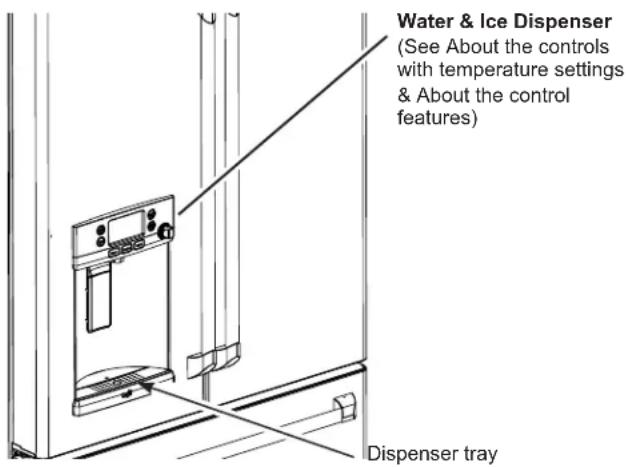
HOT WATER DISPENSER
WARNING

alding Hazard.
The hot water dispenser is capable of heating water to a temperature of approximately 185^ F ( 85^ C). Water temperatures above 125^ F ( 52^ C) can cause severe burns or death from scalding. Children, the disabled, and the elderly are at highest risk of being scalded.
Use this appliance only for its intended purpose as described in this Owner's Manual. To reduce the risk of severe burns, scald injuries, or death when using your hot water dispenser, the instructions below must be followed:
■ Do not leave container unattended around children during or after hot water dispense.
■ Do not permit children to use the hot water dispenser.
■ The hot water dispensing knob requires both twist and push motions in order to reduce the risk of hot water being dispensed unintentionally or by small children. Do not tamper with or modify the hot water dispensing knob.
■ The water coming from the dispenser is very hot. Use extreme caution when dispensing and drinking water. Allow water to cool to a drinkable temperature before drinking. Your container should be close to the dispensing point to minimize the splashing of hot water.
■ When dispensing hot water, the container can become very hot. Use a temperature insulating container, such as ceramic or foam. Using container materials such as paper or plastic may result in a burn while holding the cup. Do not use glass containers, as thermal shock can cause the container to break and may result in scalding or lacerations.
- Always follow the formula manufacturer's instructions for preparation of baby formula. When dispensing water below 125^ (51.67 cm), always test the temperature of the water before drinking.
■ The first time the hot water feature is used, confirm if you live above 5000 feet (1524 meters) (high altitude). This limits the temperature of the hot water system to avoid boiling. To access the high altitude selection, go to the settings menu.
■ A newly installed water filter cartridge will cause water to spurt from the dispenser. Run 2 gallons (7.57 liters) of water through the cold water dispenser (about 5 minutes) to remove air from the system. Until this air is removed from the system through the cold water dispenser, DO NOT use the hot water dispenser as it may result in spurting of hot water and lead to hot water scalding.
■ Do not use with water that is microbiologically unsafe or of unknown quality.
■ The hot water dispenser is designed to only dispense water. Do not attempt to heat or dispense anything other than water. Do not attempt to disassemble or clean the tank.
■ Do not modify the hot water system. Service with factory replacement part only.
READ AND SAVE THESE INSTRUCTIONS
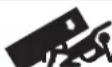
1 Space-saving ice maker*
Ice maker and bin are located on the door creating more usable storage space.
2 Showcase LED lighting
LED lighting is positioned throughout the interior to spotlight areas in the refrigerator. LEDs are located under the fresh food door to light the freezer when opened.
3 Drop-down tray* Allows for extra door storage when you need it and tucks away when you don't.
4 Full-width temperature controlled drawer
Adjustable temperature control bin that can accommodate larger items.
5 Dairy bin Separate compartment for your items.
6 Ice bin/Ice maker* Ice maker with ice storage bins.
7 QuickSpace™ shelf* Functions as a normal full-sized shelf when needed and easily slides back to store tall items below.
8 Spillproof shelves
Designed to capture your spills for easier clean up.
9 Anti-slip Mat
Liner that captures spills, keeps containers from shifting when the door is opened and is easily removable for cleaning.
10 Removable door bin
Can be removed for those with a wall limiting the door opening.
11 Climate zone bin
Separate bins for produce storage.
12 Water filter
Filters water and ice.
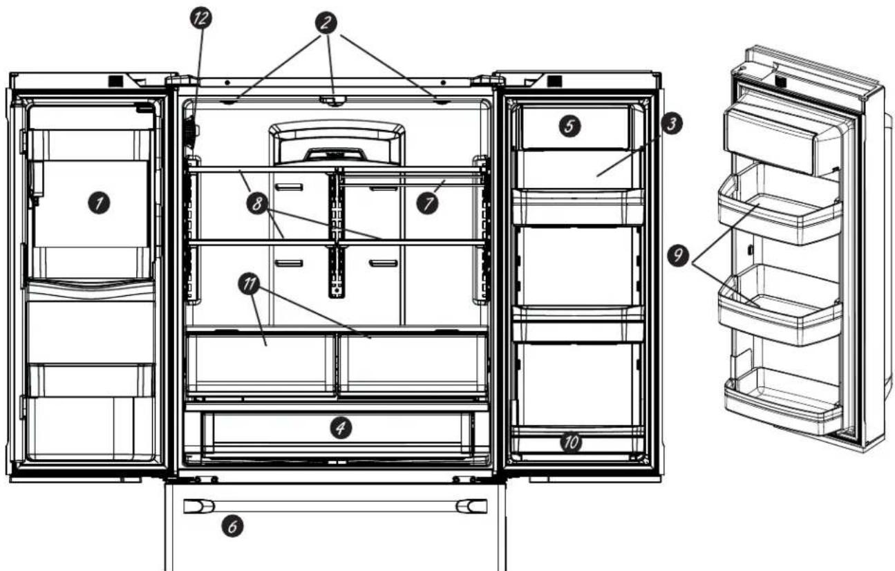
1 Door ice bin\*
- Open left fresh food door.
- Pull down latch to release bin door.
- Using handhold lift ice bucket up and out to clear locators in bottom of bin.
- To replace the ice bucket, set it on the guide brackets and push until the ice bucket seats properly.
- If bucket cannot be replaced, rotate the Ice Bucket Fork 1/4 turn clockwise.
2 Drop down dairy bin\*
- Open right fresh food door.
- Depress both buttons on lower sides and bin will drop down.
- Reverse to reinstall.
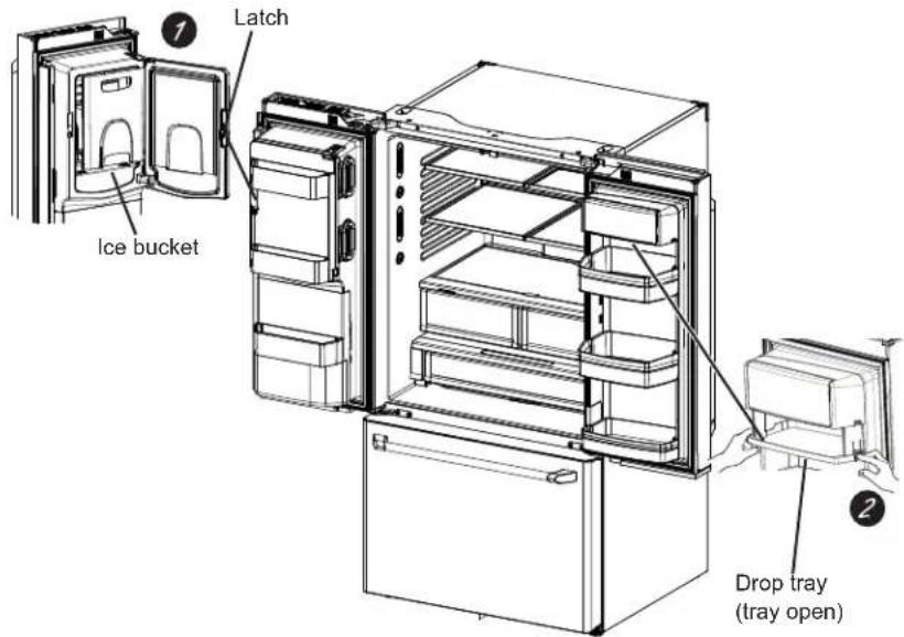
3 Ice/water filter
Remove filter/bypass plug
Push the indent on the cover and open filter door. If your unit is equipped, pull out on filter/ bypass plug and pull straight back to remove.
Installing the filter cartridge
Push the indent at the bottom of the cover and open. Lift door and align tabs on filter to filter/holder and push filter into place.
CYE/CFE Control Style
Changing the Temperature for Control Style CYE/CFE
To Change the Refrigerator Temperature:
Access By: Temperature Button Temperature
Activate By: Below the word "Refrigerator", use the arrows to select the desired temperature. Press DONE when finished to return to HOME screen.
To Change the Freezer Temperature:
Access By: Temperature Button Temperature
Activate By: Below the word "Freezer", use the arrows to select the desired temperature. Press DONE when finished to return to HOME screen.
To turn OFF cooling system, access SETTINGS from the HOME screen. Page over and tap COOLING SYSTEM ON. Press DONE to return to HOME screen.
To turn ON cooling system, access SETTINGS from the HOME screen. Page over and tap COOLING SYSTEM OFF. Press DONE to return to HOME screen.
Turning the cooling system off stops the cooling to refrigerator, but it does not shut off the electrical power.
NOTE: For optimal temperature performance, we recommend to avoid placing food or other items directly at the air flow vents or the fresh food air tower, thus blocking the air flow.
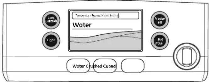
CWE Control Style
Changing Temp. for Control Style CWE
Temperature Display is located on inside of left-hand refrigerator door. To change the temperature, press and release the REFRIGERATOR or FREEZER pad.
The ACTUAL TEMP light will come on and the display will show the actual temperature. To change the temperature, tap either the
REFRIGERATOR or FREEZER pad until the desired temperature is displayed.
To turn OFF cooling system, press and hold the
REFRIGERATOR and FREEZER pads simultaneously for 3 seconds. When the cooling system is OFF the display should read OFF.
To turn ON cooling system, press either
REFRIGERATOR or FREEZER pad. The display will show the preset temperature settings of 37^ F ( 3^ C) for refrigerator and 0^ F (-18°C) for freezer. Turning the cooling system off stops the cooling to refrigerator, but it does not shut off the electrical power.
Control Style A, External Controls CFE/CYE Models
NOTE: The refrigerator is shipped with protective film covering the temperature controls. If this film was not removed during installation, remove it now.
The temperature controls are preset in the factory at 37^ F for the refrigerator compartment and 0^ F for the freezer compartment. Allow 24 hours for the temperature to stabilize to the preset recommended settings.
The temperature controls can display both the SET temperature as well as the actual temperature in the refrigerator and freezer. The actual temperature may vary slightly from the SET temperature based on usage and operating environment.
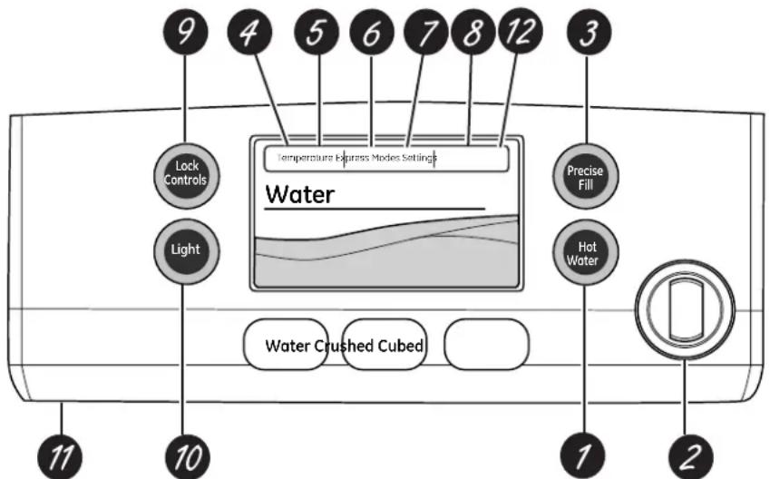
1 Hot Water
7 Dispenses up to 10 ounces of filtered hot water from user selected ranges of 90°F to 185°F.
2 Hot Water Knob
Illuminates to indicate hot water is ready. Dispenses with two motions: a counter-clockwise twist and then push to dispense.
2 Precise Fill
Precisely dispenses filtered water in accurate measurements in ounces, cups, quarts, or liters using paddle.
Refrigerator temp control
Adjust freezer compartment temperature.
Fresh food temp control
Adjust fresh food compartment temperature.
TurboFreeze™ setting
Activate TurboFreeze to quickly restore freezer temperatures after frequent door openings.
TurboCool™ setting
7 Activate TurboCool to quickly restore fresh food temperature after frequent door openings.
Humidity setting
Humidity setting can be normal or high.
Lock controls
Press and hold 3 seconds to lock out ice and water dispenser and all feature and temperature buttons.
10 LED dispenser light
10 LED lighting that can be turned on/off to light your dispenser.
11 Photo Upload
Insert USB memory stick to upload personal photos to the refrigerator LCD screen. LCD will provide on screen prompts to load and view slideshow. Make sure the photos are in the root directory in your USB.
12 Additional Settings
- Connected Home ready
- Slideshow
- Reset filter
- Ice maker on/off
- Door alarm
- Sound control
• Cooling system On/Off
- Metric/English units
- Altitude
Additional Modes
- Sabbath Mode
Press and hold lock & light simultaneously for 3 seconds to enter/exit Sabbath mode. Sabbath Mode will turn off or dim interior lights, temperature control and advanced features. Compressor will run on a timed defrost when in Sabbath mode.
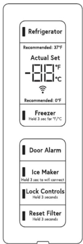
Controls Style B, Internal Controls CWE Models
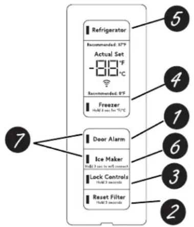
1 Door Alarm
Sounds to alert when the freezer or fresh food doors have been left open.
2 Reset Filter
Hold for 3 seconds after replacing filter.
3 Lock Controls
Press and hold 3 seconds to lock out ice and water dispenser and all feature and temperature buttons.
4 Freezer temp control
Adjust freezer compartment temperature
5 Refrigerator temp control
Adjust fresh food compartment temperature
6 Ice maker setting
Turn your ice makers on/off.
7 Sabbath Mode
Press and hold Door Alarm and Ice Maker simultaneously for 5 seconds to enter/exit Sabbath Mode.
WARNING
LACERATION HAZARD
■ Never put fingers or any other object into ice crusher discharge opening. Doing so can result in contacting the ice crushing blades and lead to serious injury or amputation
■ Use a sturdy glass when dispensing ice. A delicate glass may break and result in personal injury.
If no water is dispensed when the refrigerator is first installed, there may be air in the water line system. Press the dispenser paddle for at least five minutes to remove trapped air from the water line and to fill the water system. To flush out impurities in the water line, throw away the first six full glasses of water.
To remove Dispenser Tray
■ Pull Dispenser Tray out until it stops.
- Locate tab in the center on the bottom and push up.
■ Pull Dispenser Tray assembly out.
■ Lift metal Dispenser Tray out at center notch to clean.
To reinstall Dispenser Tray
■ Place the Dispenser Tray cover on top of catch tray and position under the two plastic retainers on either side.
■ Center Dispenser tray, and align with center guides.
■ Push in until is firmly in place.
Important Facts About Your Dispenser
■ Do not add ice from trays or bags to the door ice maker bucket. It may not crush or dispense.
■ Avoid overfilling glass with ice and use of narrow glasses. Backed-up ice can jam the chute or cause the door in the chute to freeze shut. If ice is blocking the chute remove the ice bucket, poke it through with a wooden spoon.
■ Beverages and foods should not be quick-chilled in the door ice maker bin. Cans, bottles or food packages in the storage drawer may cause the ice maker or auger to jam.
■ To keep dispensed ice from missing the glass, put the glass close to, but not touching, the dispenser opening.
■ Some crushed ice may be dispensed even though you selected CUBED ICE. This happens occasionally when a few cubes accidentally get directed to the crusher.
■ After crushed ice is dispensed, some water may drip from the chute.
■ Sometimes a small mound of snow will form on the door in the ice chute. This condition is normal and usually occurs when you have dispensed crushed ice repeatedly. The snow will eventually evaporate.
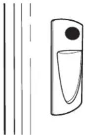
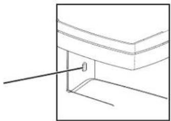
To Use the Internal Water Dispenser (CWE Models Only)
natural_image
Simple line drawing of a vertical line and a droplet inside a container (no text or symbols)
The water dispenser is located on the left wall inside the refrigerator compartment.
To dispense water:
- Hold the glass against the recess.
- Push the water dispenser button.
- Hold the glass underneath the dispenser for 2–3 seconds after releasing the dispenser button. Water may continue to dispense after the button is released.
If no water is dispensed when the refrigerator is first installed, there may be air in the water line system. Press the dispenser button for at least 5 minutes to remove trapped air from the water line and to fill the water system. During this process, the dispenser noise may be loud as the air is purged from the water line system. To flush out impurities in the water line, throw away the first 6 glassfuls of water.
NOTE: To avoid water deposits, the dispenser should be cleaned periodically by wiping with a clean cloth or sponge.
Hot Water
Hot Water Only Models
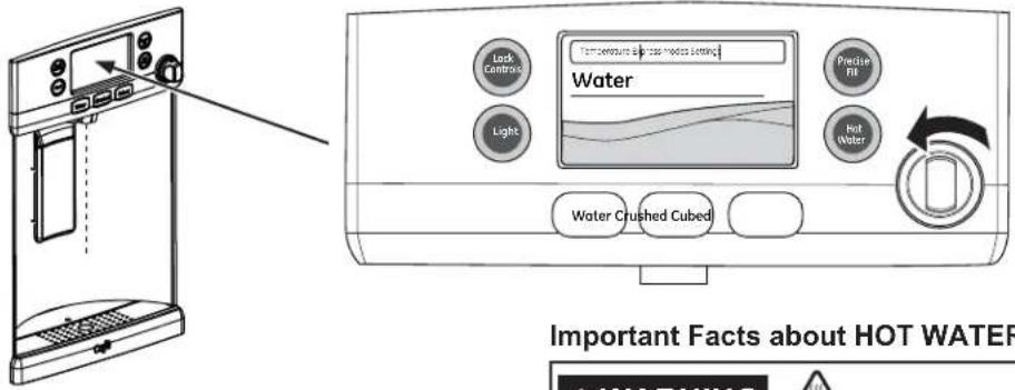
To Use Hot Water Dispenser
■ Press HOT WATER button.
■ Select desired water temperature on the LCD screen (90, 150, 170, 185, or Custom).
■ When hot water is ready (indicated on the screen and by a beeping sound) hold container with left hand centered in the recess under the spout.
■ To dispense water, rotate the hot water knob counterclockwise and then push it in. The knob must be held in during dispense.
Important Facts about HOT WATER
WARNING

LDING HAZARD.
■ The water coming from the dispenser is very hot and can cause scalds or burns. Read all warnings on page 5 prior to use.
■ Always use a container that is suitable for hot liquids (ceramic, foam, etc.)
■ The maximum single hot water dispense amount is 10 oz. Additional hot water can be dispensed by restarting the hot water feature through the LCD screen.
■ HOT WATER works best with household water pressure of 40 to 100 psi.
■ HOT WATER will time out if unused and may require a short reheat time.
For Models with K-Cup Brewing System
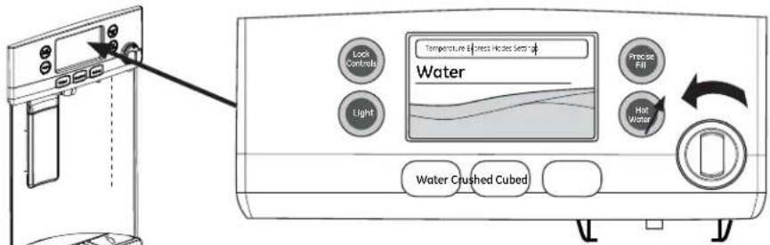
On Café refrigerators equipped with the K-Cup brewing system, ALL HOT WATER is dispensed from stainless steel dispense tube located under the right side of the control panel. The hot water is not dispensed from the center of the recess area.
To Use Hot Water Dispenser
■ Press HOT WATER button.
■ Select desired water temperature on the LCD screen (90, 150, 170, 185, or Custom).*
*If selecting "Keurig K-Cup Pod", the hot water system will change into K-Cup mode. See page 14 for K-Cup mode instructions.
■ When hot water is ready (indicated on the screen and by a beeping sound) hold container with left hand centered in the recess under the spout.
■ To dispense water, rotate the hot water knob counterclockwise and then push it in. The knob must be held in during dispense.
Important Facts about HOT WATER
WARNING

alding Hazard
■ See Hot Water Warning: Scalding Hazard above.
■ Do no permit children to use the brewer.
■ Always use a container that is suitable for hot liquids (ceramic, foam, etc.)
■ Do not brew into a mug made of glass. Doing so may cause the glass to crack or break.
Single Serve Keurig K-Cup Brewer
How to use the single serve dispenser

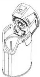
Load Keurig K-Cup into brewer.
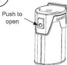
Drop K-Cup into brewer and press down firmly.
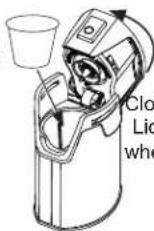
Close brewer. Lid will click when secure.
CAUTION
Cut/Puncture Hazard.
- There are two sharp needles located inside the K-Cup brewer. To avoid risk of injury, do not put your fingers inside the brewer. Use caution when cleaning.
- Keep the K-Cup brewer out of the reach of children, as they may be injured in using the K-Cup brewer incorrectly.

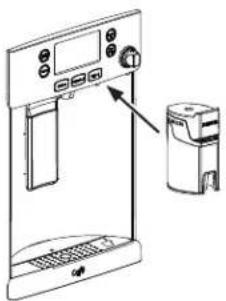
Two ways to brew:
- Press Hot Water. Select K-Cup Pod. OR
- Slide the brewer into the rails.
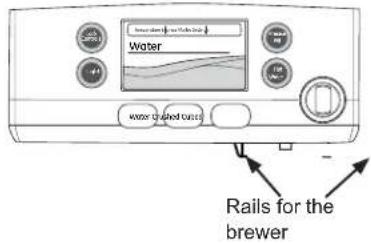

Pick your size.
NOTICE: If using a powdered beverage, select the Cocoa setting.
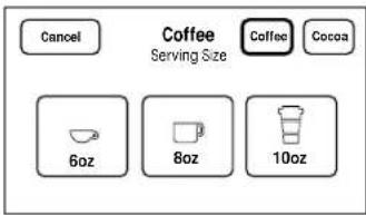

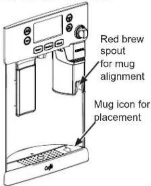
Place your mug under the brewer (on the tray mug icon and under the red brew spout).
NOTICE: Make sure the mug being used is large enough for the size selected.

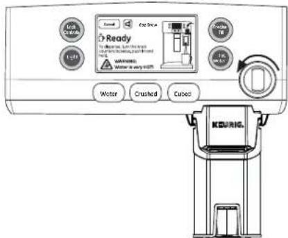
Rotate the hot water knob counterclockwise and push in to brew and dispense.
NOTICE: Press any button or dispenser paddle, or open either the left or right door to cancel dispense.
Cleaning the brewer
■ The K-Cup brewer is dishwasher safe. To clean it, open the lid and place the K-Cup brewer in the top rack of your dishwasher and run in a normal wash cycle.
■ To maximize performance of your brewer, it is recommended to rinse it thoroughly after washing to remove all soap residue.
■ Periodic cleaning of dispenser recess area is recommended as staining may occur with usage of the K-Cup brewer.
Appliance Communication (for customers in the United States and its territories)
WiFi Connect
WiFi Connect Enabled\*
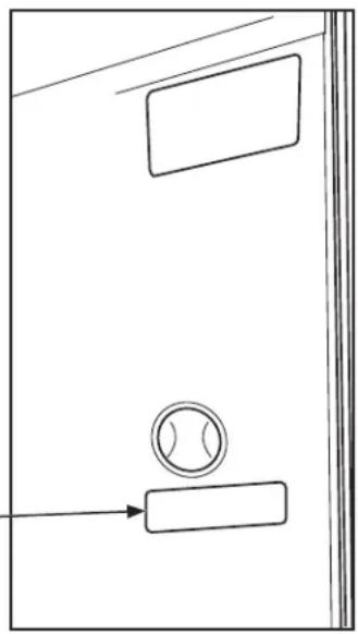
If your refrigerator has a Connected Appliance information label located on the inside as shown, your refrigerator can be connected to your WiFi network, allowing it to communicate with your smart phone for remote monitoring, control and notifications. Depending on the refrigerator model you have, you either have a WiFi communication card built into the product, or a port for an external WiFi ConnectPlus Module (sold separately). Please visit cafeappliances.com/connect to learn more about connected appliance features, and to learn what connected appliance apps will work with your Smart Phone.
natural_image
Simple line drawing of a door with a circular component and an arrow pointing to it (no text or symbols)
Connected Appliance Information
Contains FCCID: ZKJ-WCATA003
Network: GE_MODULE_XXXX
Contains IC: 10229A-WCATA003
Password: XXXXXXXXX
MAC ID: D8-28-C9-XXXXXXXXX
PT. NO. 257C2110G001
FCC/IC Compliance Statement:
This device complies with Part 15 of the FCC Rules. Operation is subject to the following two conditions:
- This device may not cause harmful interference, and
- This device must accept any interference received, including interference that may cause undesired operation.
This equipment has been tested and found to comply with the limits for a Class B digital device, pursuant to Part 15 of the FCC Rules. These limits are designed to provide reasonable protection against harmful interference in a residential installation. This equipment generates uses and can radiate radio frequency energy and, if not installed and used in accordance with the instructions, may cause harmful interference to radio communications. However, there is no guarantee that interference will not occur in a particular installation. If this equipment does cause harmful interference to radio or television reception, which can be determined by turning the equipment off and on, the user is encouraged to try to correct the interference by one or more of the following measures:
- Reorient or relocate the receiving antenna.
- Increase the separation between the equipment and receiver.
- Connect the equipment into an outlet on a circuit different from that to which the receiver is connected.
- Consult the dealer or an experienced radio/television technician for help.
Labelling: Changes or modifications to this unit not expressly approved by the manufacturer could void the user's authority to operate the equipment.
*Select Models Only
Fresh Food Storage Options
Rearranging the Shelves
Shelves in the refrigerator compartment are adjustable.
To remove:
1 Remove all items from the shelf.
2 Tilt the shelf up at the front.
3 Lift the shelf up at the back and bring the shelf out.
To replace:
While tilting the shelf up, insert the top hook at the back of the shelf in a slot on the track.
2 Lower the front of the shelf until the bottom of the shelf locks into place.
Spillproof Shelves
Spillproof shelves have special edges to help prevent spills from dripping to lower shelves.
natural_image
Line drawing of hands holding a rectangular object with a grid-like structure attached (no text or symbols)
Quick Space Shelf \*
This shelf splits in half and slides under itself for storage of tall items on the shelf below.
This shelf can be removed and replaced or relocated (just like spillproof shelves).
NOTE: The back half of the Quick Space Shelf is not adjustable.
natural_image
Line drawing of a hand pressing down on a laptop screen with an arrow indicating the next page (no text or symbols present)
Non-Adjustable Dairy Bin\*
To remove: Lift the dairy bin straight up, then pull out.
To replace: Engage the bin in the molded door supports and push down. The bin will lock in place. See page 36.
natural_image
Technical line drawing of a mechanical device with no visible text or symbols
Fresh Food Storage Options
Adjustable Bins on the Door
Adjustable bins can easily be carried from refrigerator to work area.
To remove: Lift bin straight up, then pull out.
To replace or relocate: Slide in the bin just above the molded door supports, and push down. The bin will lock in place.
Drop down tray \*
(tray open)
- Open right fresh food door
- Depress both buttons on lower sides of bin and bin will drop down.
- Reverse to reinstall.
natural_image
Technical line drawing of a mechanical device with no visible text or symbols
natural_image
Technical line drawing of an open refrigerator with internal compartments and handlebars (no text or labels)
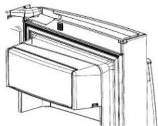
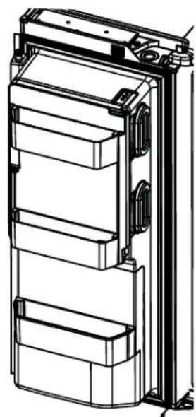
Non-Adjustable Bins on the Door (Dispenser Models - Left Hand Door)
To remove: Lift the bin straight up, then pull out.
To replace: Engage the bin in the molded supports on the door and push down. It will lock in place.
The ice maker door bins are not interchangeable, note the location upon removal and replace the bin in its proper location.
natural_image
Technical line drawing of a multi-tiered mechanical or electrical enclosure with mounting brackets and structural details (no text or symbols)
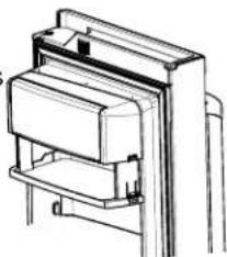
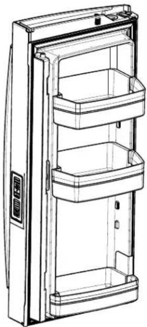
Non-Dispense Models (Left Hand Door)
natural_image
Technical line drawing of a refrigerator internal compartments (no text or symbols)
*Select Models Only
Climate Zone & Temperature Controlled Drawer
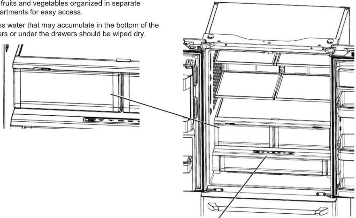
ClimateZone
Keep fruits and vegetables organized in separate compartments for easy access.
Excess water that may accumulate in the bottom of the drawers or under the drawers should be wiped dry.
Temperature Controlled Drawer
The Temperature Controlled Drawer is a full-width drawer with adjustable temperature control. This drawer can be used for large miscellaneous items.
To change setting, press select button.
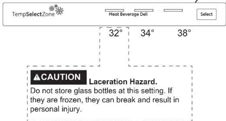
NOTE: Temperatures indicate the appropriate temperatures for the food and actual temperatures may vary based on normal operation and other factors such as door openings and fresh food set point.
Climate Zone & Temperature Controlled Drawer
How to Remove and Replace Drawer
To remove:
1 Pull the drawer out to the stop position.
2 Lift the front of the drawer up and out.
To replace:
1 Pull left and right slides until fully extended.
2 Place drawer back in first and rotate drawer front down to seat on slide.
3 Push the drawer in to closed position.
natural_image
Technical line drawing of a mechanical assembly with no visible text or symbols
How to Remove and Replace Drawer Divider\*
To remove:
1 Pull the drawer out to the stop position.
2 Slide pan divider to right to release it from pan.
To replace:
Reverse steps 1 and 2 to replace drawer divider.
natural_image
Technical line drawing of a mechanical assembly with a perforated component inserted into a housing (no text or symbols)
*Select Models Only
Baskets, Drawers, and Bins
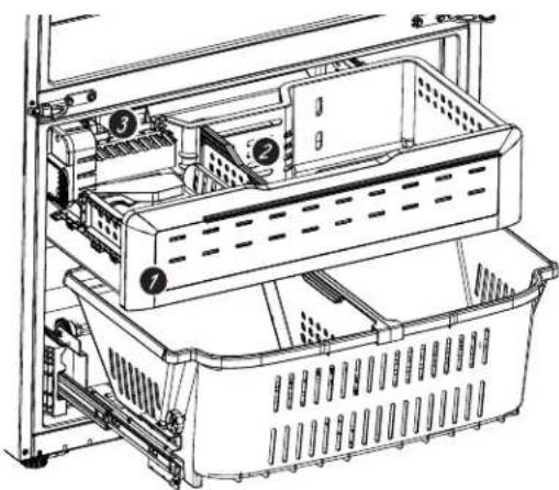
Freezer Basket and Drawer
1 Basket
② Drawer
3 Ice Bucket*
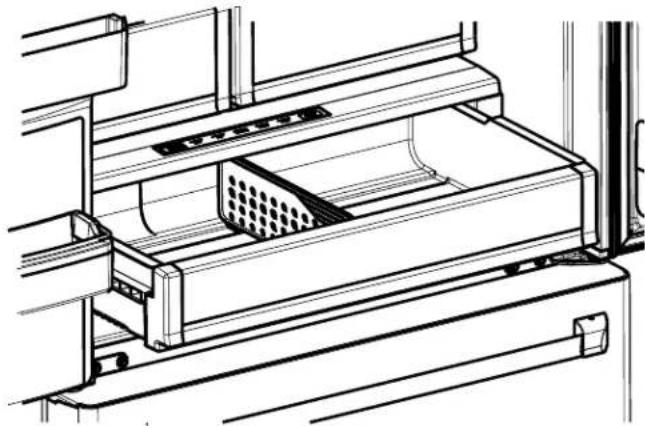
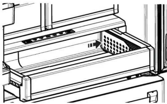
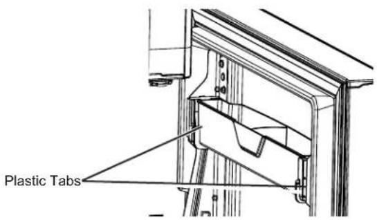
Non-Adjustable Bin in the Freezer
To remove: Push in plastic tab on either left or right side.
To replace: Slide bin into location until it locks into place.
Basket Removal
To remove, CFE only:
- Open freezer door to the stop position.
- Remove freezer door bin by pushing plastic tab on either left or right side to release bin hinge pin.
- Remove freezer basket by lifting up the rear of the basket and moving basket rearward until the front of the basket can be rotated upward and out.
- Lift it out to remove.
To remove, CYE and CWE only:
- Open fresh food doors.
- Open freezer doorto the stop position.
- Remove freezer basket by lifting up the rear of the basket and rotate it upward.
- Lift it out to remove.
To replace:
Reverse step 1 thru 4 to replace.
natural_image
Technical line drawing of a server rack with ventilation slots and directional arrows indicating movement (no text or symbols)
*Select Models Only
49-60820
Automatic Ice Maker
A newly installed refrigerator may take 12 to 24 hours to begin making ice.
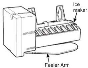
Automatic Ice maker\*
The ice maker will produce seven cubes per cycle approximately 100–130 cubes in a 24-hour period, depending on freezer compartment temperature, room temperature, number of door openings and other use conditions.
The ice maker will fill with water when it cools to 15^ F ( -10^ C). A newly installed refrigerator may take 12 to 24 hours to begin making ice cubes.
If the refrigerator is operated before the water line connection is made to the unit or if the water supply to an operating refrigerator is turned off, make sure that the ice maker is turned off. Once the water has been connected to the refrigerator, the ice maker may be turned on. See the table below for details.
You may hear a buzzing sound each time the ice maker fills with water.
Throw away the first few batches of ice to allow the water line to clear.
Be sure nothing interferes with the sweep of the feeler arm.
When the bin fills to the level of the feeler arm, the ice maker will stop producing ice. It is normal for several cubes to be joined together.
If ice is not used frequently, old ice cubes will become cloudy, taste stale and shrink.
NOTE: In homes with lower-than-average water pressure, you may hear the ice maker cycle multiple times when making one batch of ice.
CAUTION
To minimize the risk of personal injury, avoid contact with the moving parts of the ejector mechanism, or with the heating element that releases the cubes. Do not place fingers or hands on the automatic ice making mechanism while the refrigerator is plugged in.
How to Turn the Ice Maker On/Off
| Display Type (See Page 8) Model # How to turn the ice maker on/off |
| Control Style A CYE/CFE Use the settings menu on the touchscreen |
| Control Style B CWE Use the “ICE MAKER” button on the control |
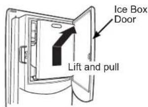
Ice Bucket and Dispenser\*
- Open the ice box door on inside of the left door.
- Pull up and out on the ice bucket in the left hand door to remove it from the compartment.
- To replace the ice bucket, set it on the guide brackets and push until the ice bucket seats properly.
- If bucket cannot be replaced, rotate the ice bucket fork 1/4 turn clockwise.
natural_image
Technical line drawing of a mechanical assembly with a close-up view showing internal components (no text or symbols)
*Select Models Only
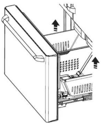
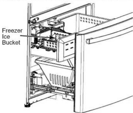
Freezer Ice Bucket\*
The ice storage is in the freezer compartment drawer.
- Open the freezer drawer.
- The ice bucket is located on the left side of the upper basket.
- Pull the upper basket forward to remove the ice bucket.
Care and Cleaning
Cleaning the Outside
The stainless steel panels, door handles and trim.
The stainless steel doors and door handles (on some models) can be cleaned with a commercially available stainless steel cleaner. Cleaners with oxalic acid such as Bar Keepers Friend Soft Cleanser™ will remove surface rust, tarnish and small blemishes. Use only a liquid cleanser free of grit and rub in the direction of the brush lines with a damp soft sponge. Do not use appliance wax or polish on the stainless steel.
Silver-accented plastic parts.
Wash parts with soap or other mild detergents. Wipe clean with a sponge, damp cloth or paper towel. Do not use scouring pads, powdered cleaners, bleach or cleaners containing bleach because these products can scratch and weaken the paint finish.
Should spill tray need cleaning use lime remover.
Cleaning the Inside
Unplug the refrigerator before cleaning.
If this is not practical, wring excess moisture out of sponge or cloth when cleaning around switches, lights or controls.
Use an appliance wax polish on the inside surface between the doors.
Use warm water and baking soda solution—about a tablespoon (15 ml) of baking soda to a quart (1 liter) of water. This both cleans and neutralizes odors. Rinse and wipe dry.
CAUTION
Do not clean glass shelves or coverswith warm water when they are cold. Glass shelves and covers may break if exposed to sudden temperature changes or impact such as bumping or dropping. Tempered glass is designed to shatter into many small pieces if it breaks.
Do not wash any plastic refrigerator parts in the dishwasher.
Behind the Refrigerator
Be careful when moving the refrigerator away from the wall. All types of floor coverings can be damaged, particularly cushioned coverings and those with embossed surfaces.
Raise the leveling legs located at the bottom front of the refrigerator.
Pull the refrigerator straight out and return it to position by pushing it straight in. Moving the refrigerator in a side direction may result in damage to the floor covering or refrigerator.
Lower the leveling legs until they touch the floor.
WARNING
ELECTRICAL SHOCK HAZARD
When pushing the refrigerator back, make sure you don't roll over the power cord or water supply line.
Preparing for Vacation
For long vacations or absences, remove food and unplug the refrigerator. Clean the interior with a baking soda solution of one tablespoon (15 ml) of baking soda to one quart (1 liter) of water. Leave the doors open.
LCD Models: turn refrigerator off at control.
If the temperature can drop below freezing, have a qualified service technician drain the water supply system to prevent serious property damage due to flooding.
- Turn refrigerator off or unplug the refrigerator.
- Empty ice bucket
- Turn water supply off
If you cut the water supply off, turn off the ice maker.
Upon returning from vacation:
- Replace the water filter.
- Run 2 gallons (7.57 liters) of water through the cold water dispenser (about 5 minutes) to flush the system.
- Dispense 185°F (85°C) hot water 3 times (10 oz. each) to flush the system.
Care and Cleaning
Preparing to Move
Secure all loose items such as shelves and drawers by taping them securely in place to prevent damage.
When using a hand truck to move the refrigerator, do not rest the front or back of the refrigerator against the hand truck. This could damage the refrigerator.
Handle only from the sides of the refrigerator.
Be sure the refrigerator stays in an upright position during moving.
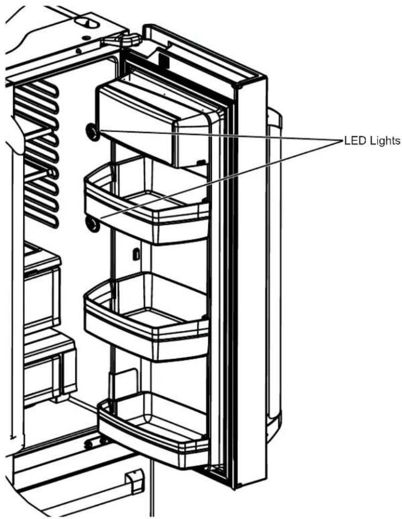
Refrigerator Lights (LEDs)
There is LED lighting in fresh food compartment and on the bottom of the fresh food doors to light the freezer compartment.
An authorized technician will need to replace the LED light.
If this assembly needs to be replaced, schedule service on-line at cafeappliances.com/service.
Installation Instructions
Bottom Freezer Refrigerator
Questions? Visit our Website at: cafeappliances.com
In Canada, visit cafeappliances.ca
BEFORE YOU BEGIN
Read these instructions completely and carefully.
WARNING

ver Hazard.
Built-in style models (model CYE and CWE) are top heavy, especially with any doors open. These models must be secured with the anti-tip floor bracket to prevent tipping forward, which could result in death or serious injury. Read and follow the entire installation instructions for installing the anti-tip floor bracket packed with your refrigerator.
- IMPORTANT — Observe all governing codes and ordinances. Save these instructions for local inspector's use.
- Note to Installer – Be sure to leave these instructions with the Consumer.
- Note to Consumer – Keep these instructions for future reference.
- Skill level – Installation of this appliance requires basic mechanical skills.
- Completion time – Refrigerator Installation can vary
Water Line Installation
30 minutes
- Proper installation is the responsibility of the installer.
- Product failure due to improper installation is not covered under the Warranty.
PREPARATION
MOVING THE REFRIGERATOR INDOORS
If the refrigerator will not fit through a doorway, the refrigerator door and freezer drawer can be removed.
- To remove the refrigerator door, see the Installing the Refrigerator section.
- To remove the freezer drawer, see the Removing the Freezer Drawer section.
WATER SUPPLY TO THE ICE MAKER AND DISPENSER
If the refrigerator has an ice maker, it will have to be connected to a cold water line. A Café water supply kit (containing tubing, shutoff valve, fittings and instructions) is available at extra cost from your dealer, by visiting our website at cafeappliances.com/parts. In Canads, visit cafeappliances.ca/parts.
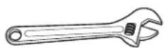
Adjustable Wrench
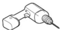
3/8" Socket Ratchet/Driver
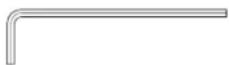
1/8", 3/32", 1/4" & 5/32"
Allen Wrenches

Phillips-Head Screwdriver


1/4" Outer Diameter Compression Nut and Ferrule (sleeve)
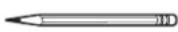
Pencil
1/8" Drill Bit and Electric or Hand Drill
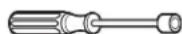
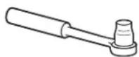
1/4" Nut Driver
Tape Measure
Pliers
Flat-Head Screwdriver
Torx T20, T25
DIMENSIONS All measurements are given with leveling leg fully retracted.
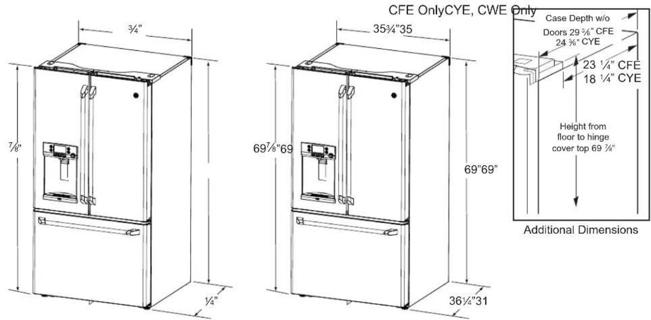
| CFE | CYE, CWE |
| Overall Height to Top of Hinge Cover | 69^7/8" | 69 78" |
| Height to Top of Cabinet | 69" | 69" |
| Case Depth without Doors 29 | ^3/8" | 24 38 |
| Overall Exterior Case Width | 35^3/4" | 35 34" |
| Overall Exterior Depth Doors/Drawers with Handles | 36^1/4" | 31^1/4" |
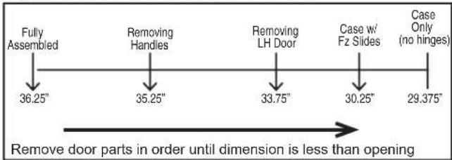
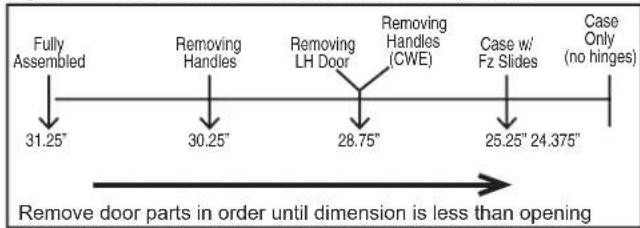
MOVING THE REFRIGERATOR
- Using the chart below determine if the width of your passageway can accommodate the depth of the refrigerator. Ensure you have clearance to prevent damage to the refrigerator before safely moving it to the final location.
- If passageways are large enough to accommodate the refrigerator without removing the handles skip to Step 6. Leave tape, film and all packaging on doors until the refrigerator is in the final location.
If your model number starts with CFE
- NOTE: Use a padded hand truck or moving straps to move this refrigerator. Place the refrigerator on the hand truck with a side against the truck. We strongly recommend that two people move and complete this installation.
If your model number starts with CYE, CWE
INSTALLING THE REFRIGERATOR
REFRIGERATOR LOCATION
■ Do not install the refrigerator where the temperature will go below 60^ F ( 16^ C) because it will not run often enough to maintain proper temperatures.
■ Do not install the refrigerator where the temperature will go above 100^ F ( 37^ C) because it will not perform properly.
■ Do not install the refrigerator in a location exposed to water (rain, etc.) or direct sunlight.
■ Install it on a floor strong enough to support it fully loaded.
CLEARANCES
Allow the following clearances for ease of installation, proper air circulation and plumbing and electrical connections.
Sides 1/8" (3 mm)
Top 1" (25 mm) Cabinet/Hinge Cover
Back 2" (50 mm)
REMOVING THE REFRIGERATOR DOORS
■ IMPORTANT NOTE: This refrigerator is 36^1/4 " deep ( 31^1/4 " for CYE models). Doors and passageways leading to the installation location must be at least 36^1/4 " wide in order to leave the doors and handles attached to the refrigerator while transporting it into the installation location. If passageways are less than 36^1/4 ", the refrigerator doors and handles can easily be scratched and damaged. The top cap and doors can be removed to allow the refrigerator to be safely moved indoors. If passageways are less than 31^1/4 ", start with Step 1.
■ If it is not necessary to remove doors, skip to Step 11. Leave tape and all packaging on doors until the refrigerator is in the final location.
■ NOTE: Use a padded hand truck to move this refrigerator. Place the refrigerator on the hand truck with a side against the truck. We strongly recommend that TWO PEOPLE move and complete this installation.
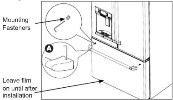
① REMOVE THE FRESH FOOD DOOR HANDLE
Handle Design varies based on models, however Installation is same.
Stainless steel and plastic handles:
A Loosen the set screws with the 1/8" Allen wrench and remove the handle.
NOTE: If the handle mounting fasteners need to be tightened or removed, use a 1/4" Allen wrench.
② REMOVE THE FREEZER DOOR HANDLE
Handle Design varies based on models, however Installation is same.
Stainless steel and plastic handles:
A Loosen the set screws with the 1/8" Allen wrench and remove the handle.
NOTE: If the handle mounting fasteners need to be tightened or removed, use a 1/4" Allen wrench.
Reinstall the handles using the same procedure as removing.
INSTALLING THE REFRIGERATOR (Cont.)
③ REMOVE THE REFRIGERATOR DOORS
WARNING
Follow all steps for removing and reinstalling the door. Failure to follow these instructions, leaving off parts, or overtightening screws, can lead to the door falling off and result in injury and property damage.
A Securely tape the door shut with masking tape or have a second person support the door.
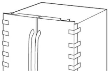
natural_image
Pure technical line drawing of a mechanical component with no text or symbols
B Start with left-hand door first: Remove the hinge cover on top of the left refrigerator door by removing all hex screws and pulling it up. Do the same for the right-hand door and the middle cover.
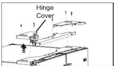
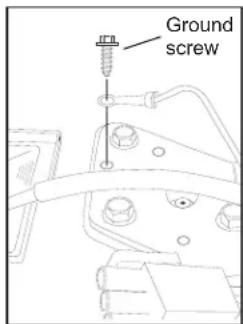
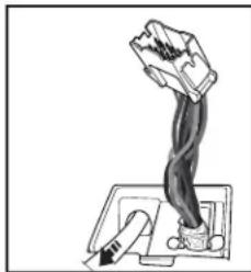
C Disconnect both electrical connectors at the top
cover.
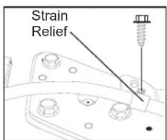
Remove the 1/4" hex head screw to disconnect the ground wire from the hinge. Remove the 1/4" hex head screw to remove the strain relief from th
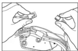
natural_image
Line drawing of hands holding a small electronic component (no text or symbols visible)
③ REMOVE THE REFRIGERATOR DOORS (cont)
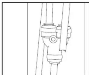
D Disconnect the water line from the back of the unit by pressing down on the dark grey collar while pulling up on the water line. Pull waterline through case conduit from the top to free the line for door removal. The water line is more than 4' long and may need to be taped to Door for accessibility when reinstalling.
natural_image
Pure mechanical assembly diagram without any text, numbers, or symbols
natural_image
Diagram of a hand gripping a lever with a curved handle, no text or symbols present
E Using a 3/8" socket ratchet/driver, remove the screws securing the top hinge to the cabinet, then lift the hinge straight up to free the hinge pin from the location in the top of the door.
natural_image
Technical line drawing of a mechanical bracket with two screws inserted (no text or symbols)
CAUTION
Lifting Hazard.
Single person lift could cause injury. Use assistance when handling, moving or lifting the refrigerator doors.
NOTE: when removing door, to prevent damage to door and electronics, carefully place the door in a proper location.
NOTE: The lower door hinge pin and hinge are keyed and must be matched correctly for the door to self close properly. Please follow the directions carefully.
INSTALLING THE REFRIGERATOR (Cont.)
③ REMOVE THE REFRIGERATOR DOORS (cont)
NOTE: for proper installation later, please follow the next step carefully.
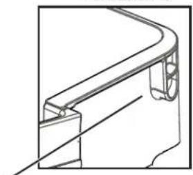
F Fresh Food doors to be REMOVED and INSTALLED opened at 90° with case front.
Lift up & off center hinge
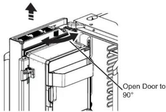
REMOVE OPPOSITE DOOR
Follow the same procedure on the opposite door. There are no wires or water lines on the opposite side
4 REMOVE CENTER HINGE (if necessary)
Remove the 3/8" screws securing the center hinge to the cabinet. Use T20 driver to remove outboard screw
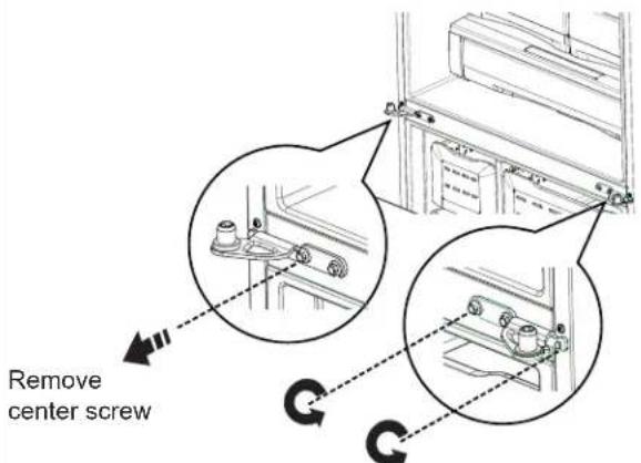
Loosen Outer screws
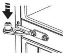
⑤ REINSTALLING THE REFRIGERATOR DOORS
Reverse steps 1 through 4 to reinstall refrigerator, follow details below for critical alignments.
A Reinstall center hinge first and torque the screws to 65 in-lb (7.34
N-m). With the LH door at 90° to the front of the case, lower the refrigerator door onto the center hinge.
Ensure that the door and hinge align correctly.
natural_image
Mechanical assembly diagram showing a bracket with mounting holes and a cylindrical component (no text or symbols)
B Rotate doors closed and make sure moveable center sealing portion of the door aligns with the striker. If the door will not self-close after reinstalling, remove door, turn door upside down, check alignment mark and arrow; (there is an alignment mark on the door closure mechanism It corresponds to an alignment mark on the bottom end cap. Rotate door closure mechanism to align mark and arrow, reinstall door).
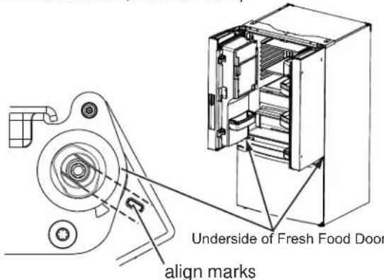
If door cannot be installed at 90° follow steps below:
- If space or model limits opening door to less than 180^ , then: a) Remove door, carefully turn door upside down.
b) Check alignment of door closure mechanism shaft on underside of door. The flats on the shaft should correspond to alignment tab on plastic ring or mark on bottom end cap.
c) If shaft is not aligned to tab/mark, using 5/32" Allen wrench, rotate door closure mechanism shaft counterclockwise for right door and clockwise for left door. Then align flat with tab/mark.
d) Install the door at 90°
Securely tape the door shut with masking tape or have a second person support the door. Reinstall the top hinge and torque the screws to 65 in-lb (7.34 N-m).
C Be sure to reinstall the ground wire and strain relief to the top hinge.
Reinstall the hinge cover. NOTE: Ensure wires are not pinched or under screw bosses before tightening screws.
Installation Instructions
INSTALLING THE REFRIGERATOR (Cont.)
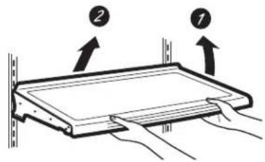
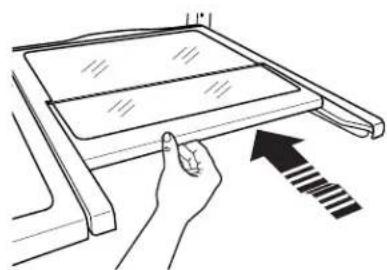
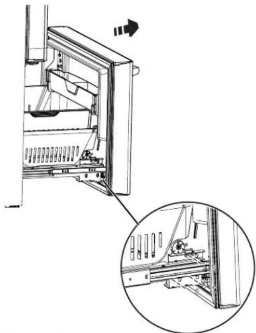
6 REMOVE THE FREEZER DOOR
A Pull the freezer door open to full extension.
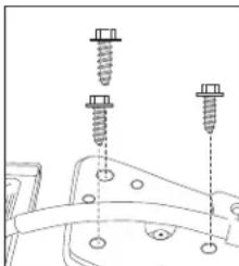
B Remove 3 attachment screws, located at the bottom on each side of the freezer door using 3/8" hex socket driver.
natural_image
Technical line drawing of a mechanical assembly with an inset close-up showing internal components (no text or symbols)
CAUTION
Lifting Hazard
Freezer door is heavy Use both hands to secure the door before lifting.
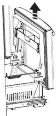
C Lift the freezer door to disengage it from the slide mechanism
natural_image
Technical line drawing of a mechanical device with an upward arrow indicating motion (no text or symbols present)
The door can safely rest on the bottom. Do not rest the door on any other surfaces to avoid scratches.
Push the slide mechanism back completely until it self retracts.
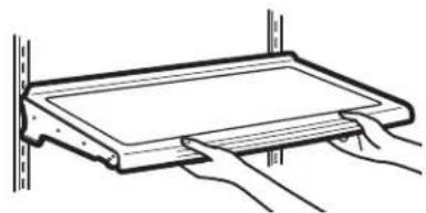
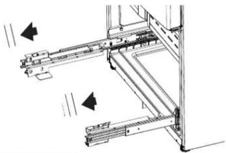
7 REPLACING THE FREEZER DOOR
A Pull the slide Mechanism to full extension using both hands simultaneously.
B Remove the basket resting on the slides.
natural_image
Technical line drawing of a mechanical assembly with no visible text or symbols
CAUTION
Lifting Hazard
Freezer door is heavy Use both hands to secure the door before lifting.
C Lift the freezer door and place it on the slide mechanism
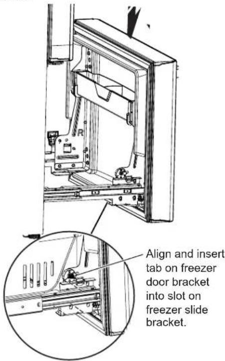
D Replace the attachment screws and torque the screws to 65 in-lb (7.34 N-m).
E For adjusting freezer door gaps, follow the instructions on pg 30.
FReplace the basket
INSTALLING THE REFRIGERATOR (Cont.)
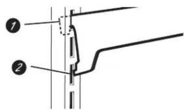
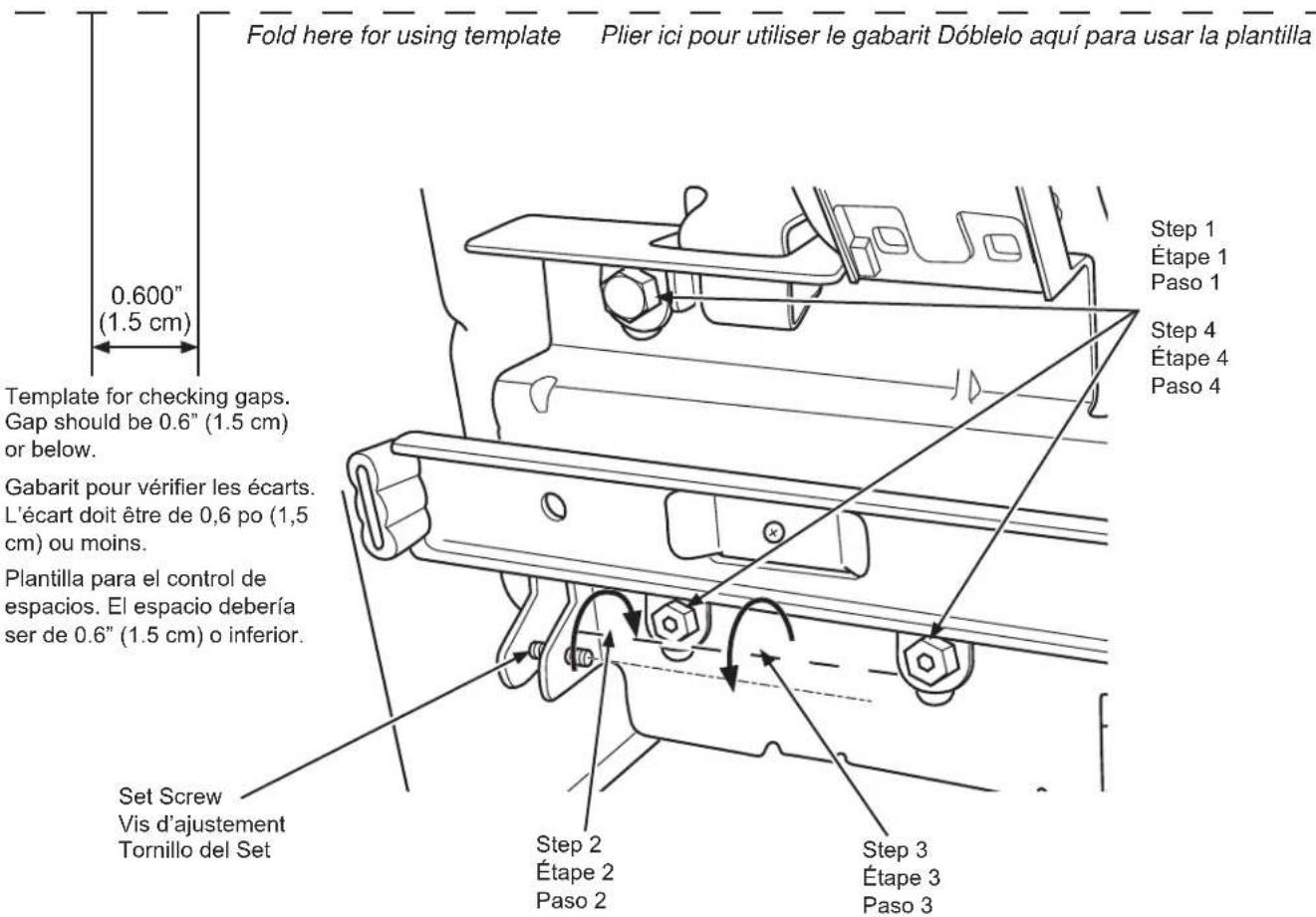
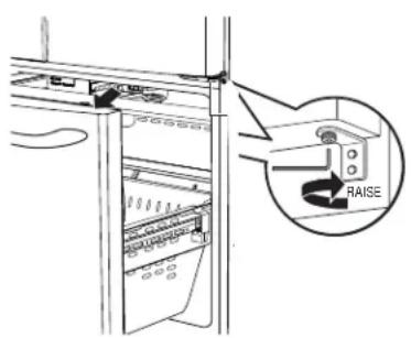
Instructions for adjusting freezer door gaps:
IMPORTANT!
The 6 mounting screws (3 on each side) are NOT interchangeable with the center or top hinge screws. Drawer screws have flat washer heads, and other screws have lines/ribs on washer heads.
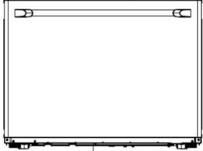
After installation of the freezer door, check for uniform gaps (top and bottom of right and left hand side) with the template provided.
In the event of excessive gaps use the following steps to adjust the freezer door.
Step 1 - Loosen the 3 screws on each side (right and left) of the freezer door.
Step 2 - Adjust set screw clockwise if gap at the top is too big (see template). Turn the set screw using 3/32" hex key clockwise by quarter to half a rotation
Step 3 - Adjust set screw counter-clockwise if gap at the bottom is too big (see template). Turn the set screw using 3/32" hex key counter-clockwise by quarter to half a rotation
Step 4 - Tighten the 3 screws on each side (right and left).
Step 5 - Re-check the gaps using the template and repeat steps 1 to 4 if required and complete with step 5.
Installation Instructions
INSTALLING THE REFRIGERATOR (Cont.)
natural_image
Technical line drawing of a mechanical assembly with an inset close-up showing internal components (no text or symbols)
A Locate the height adjuster cam in the freezer door. Slightly loosen the three door attachment screws on both sides using a 3/8" hex socket driver.
B Locate and loosen the cam screw using the T-27 screw driver.

natural_image
Technical line drawing of a mechanical assembly with no visible text or symbols
A Lift the door on the side requiring adjustment, rotate the cam to required position.
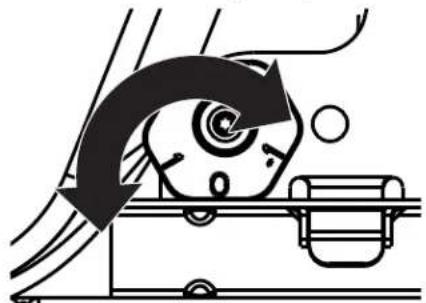
natural_image
Diagram of a mechanical device with rotating arm and base, no visible text or symbols
0 - Initial position
1 - Lift by 0.050" (0.127 cm)
-1 - Lower by 0.050" (0.127 cm)
-2 - Lower by 0.100" (0.254 cm)
-3 - Lower by 0.150" (0.381 cm)
B After adjustment tighten the 3 attachment screws using to 65 in-lb (7.34 N-m).
10 REMOVE PACKAGING
Remove all tape, foam and protective packing from shelves and drawers.
INSTALLING THE REFRIGERATOR (Cont.)
Anti-Tip Floor Bracket Installation (Models CYE and CWE only)
WARNING
er Hazard.
Built-in style models (CYE, CWE) are top heavy, especially with any doors open. These models must be secured with the anti-tip floor bracket to prevent tipping forward, which could result in death or serious injury. Read and follow the entire installation instructions for installing the anti-tip floor bracket packed with your refrigerator.
NOTE:
If you did not receive an anti-tip bracket with your purchase, visit us online at
cafeappliances.com/parts to receive one at no cost. In Canada, cafe.appliances.ca/parts.
For installation instructions of the bracket, visit:
cafeappliances.com/literature. In Canada, cafe.appliances.ca/literature.
MATERIALS YOU MAY NEED (not included)
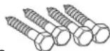
Lag Bolts
1/4" (6 mm) x 1-1/2" (38 mm)
Drill Bit Appropriate for Anchors
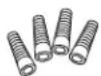
Anchor Sleeves
1/2" (12 mm) OD
For Anti-Tip Bracket Mounted on CONCRETE Floors Only
AT-1
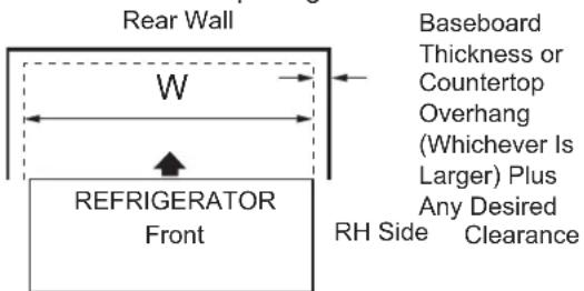
MEASURE CABINET OPENING AVAILABLE VS. REFRIGERATOR WIDTH
Measure width of cabinet opening where refrigerator will be placed, W.
Be sure to account for any countertop overhang, baseboard thickness and any clearance desired. Width, W, should not be less than 36" (91.44 cm). The refrigerator will be placed approximately in the middle of this opening.
1/8" (3 mm) Drill Bit and Electric or Hand Drill
Pencil
Tape measure
5/16" (8 mm) Nut Driver
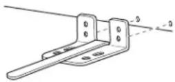
AT-2 LOCATING THE ANTI-TIP FLOOR BRACKET
A Place the anti-tip floor bracket locator template (included inside the anti-tip kit) onto the floor up against the rear wall, within W, and in line with the desired location of the RH side of the refrigerator (see Figure 1).
Figure 1 – Installation Overview
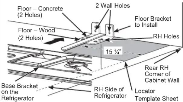
B Place the anti-tip floor bracket onto the locator template with its RH floor holes lined up with the floor holes indicated on the template sheet, approximately 15 14 " (38.73 cm) from the edge of the sheet or the RH side of the refrigerator.
C Hold down in position and use the anti-tip floor bracket as a template for marking the holes based upon your configuration and type of construction as shown in Step 3. Mark the hole locations with a pencil, nail or awl.
NOTE:
- It is REQUIRED to use at least 2 screws to mount the floor bracket (one on each side of the anti-tip floor bracket). Both must be into either the wall or the floor. Figure 2 indicates all the acceptable mounting configurations for screws. Identify the screw holes on the anti-tip floor bracket for your configuration.
Installation Instructions
INSTALLING THE REFRIGERATOR (Cont.)
Anti-Tip Floor Bracket Installation (Models CYE and CWE only)
AT-2
LOCATING THE ANTI-TIP FLOOR BRACKET (cont.)
Figure 2 – Acceptable Screw Placement Locations
Recommended Installation
– Wood
Recommended Installation
- Concrete
Minimum Acceptable #1 – Wall Plate Stud
Minimum Acceptable #2
– Wood Floor
Minimum Acceptable #3
– Concrete Floor
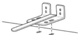
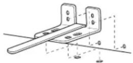
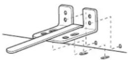
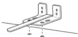
AT-3
ANTI-TIP BRACKET INSTALLATION

WOOD Wall and Floor Construction:
- Drill the appropriate number of 1/8" (3 mm) pilot holes in the center of each floor bracket hole being used (a nail or awl may be used if a drill is not available) AND remove the locator template from the floor.
- Mount the anti-tip floor bracket by fastening the 2, or recommended 4, #10-16 hex-head screws tightly into place as illustrated in Figure 3.
Figure 3 – Attachment to Wall and Floor

CONCRETE Wall and Floor Construction:
- Anchors required (not provided):
4 each 1/4" (6 mm) x 1-1/2" (38 mm) lag bolts 4 each 1/2" (12 mm) O.D. sleeve anchors
- Drill the recommended size holes for the anchors into the concrete at the center of the holes marked in Step 2.
- Install the sleeve anchors into the drilled holes. Place the anti-tip floor bracket as indicated in Step 2. Remove the locator template from the floor.
• Install the lag bolts through the anti-tip floor bracket and tighten appropriately.

WOOD Wall and TILE Floor Construction:
- For this special case, locate the 2 wall holes identified in Fig. 2. Drill an angled 1/8'' (3 mm) pilot hole (approx. as shown in Fig. 3) in the center of each hole.
- Mount the anti-tip floor bracket using the Minimum Acceptable Installation #1, as illustrated in Fig. 2.
AT-4
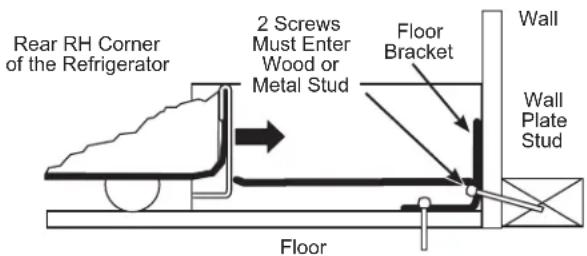
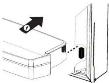
POSITIONING THE REFRIGERATOR TO ENGAGE THE ANTI-TIP FLOOR AND BASE BRACKETS
A Before pushing the refrigerator into the opening, plug the power cord into the receptacle and connect waterline (if equipped). Check for leaks.
B Locate the refrigerator's RH side and move back approximately in line with the RH side of the cabinet opening, W. This should position the anti-tip floor bracket to engage the anti-tip base bracket on the refrigerator.
C Gently roll the refrigerator back into the cabinet opening until it comes to a complete stop. Check to see if the refrigerator front lines up with the cabinet front face. If not, carefully rock the refrigerator forward and backward until engagement occurs and you notice that the refrigerator is fully pushed up against the rear wall.
D If Applicable: Adjust the rear (and front) wheel height settings to fully engage the rear anti-tip brackets, while also aligning the refrigerator front with the cabinet front face.
NOTE: If you pull the refrigerator out and away from the wall for any reason, make sure the anti-tip floor bracket is engaged when the refrigerator is pushed back against the rear wall.
INSTALLING THE REFRIGERATOR (Cont.)
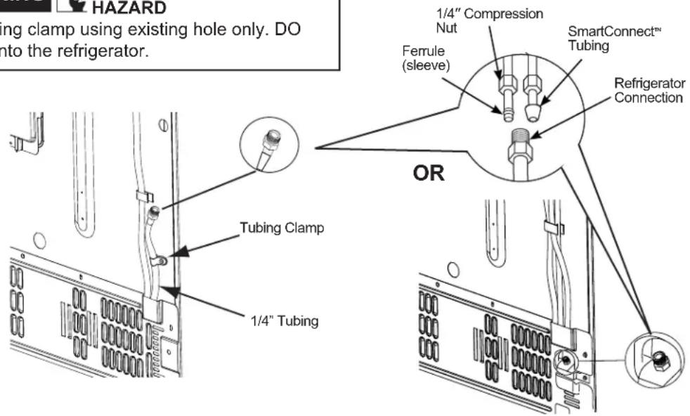
11 CONNECTING THE REFRIGERATOR TO THE HOUSE WATER LINE
A cold water supply is required for automatic ice maker operation. If there is not a cold water supply, you will need to provide one. See Installing the Water Line section.
NOTES:
- Before making the connection to the refrigerator, be sure the refrigerator power cord is not plugged into the wall outlet.
- If your refrigerator does not have a water filter, we recommend installing one if your water supply has sand or particles that could clog the screen of the refrigerator's water valve. Install it in the water line near the refrigerator. If using SmartConnect™ Refrigerator Tubing Kit, you will need an additional tube (WX08X10002) to connect the filter. Do not cut plastic tube to install filter.
- Before connecting the water line to the house, purge the house line for at least 2 minutes.
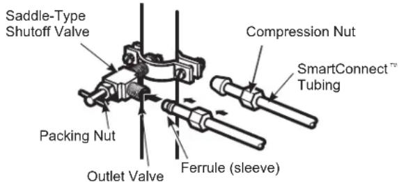
A If you are using copper tubing, place a compression nut and ferrule (sleeve) onto the end of the tubing coming from the house cold water supply.
If you are using the SmartConnect™ tubing, the nuts are already assembled to the tubing.
B If you are using copper tubing, insert the end of the tubing into the refrigerator connection, at the back of the refrigerator, as far as possible. While holding the tubing, tighten the fitting.
If you are using SmartConnect™ tubing, insert the molded end of the tubing into the refrigerator connection, at the back of the refrigerator, and tighten the compression nut until it is hand tight. Then tighten one additional turn with a wrench. Over tightening may cause leaks.
C Fasten the tubing into the clamp provided to hold it in position. You may need to pry open the clamp.
WARNING
Connect to potable water supply only.
A cold water supply is required for automatic icemaker operation. The water pressure must be between 40 and 120 psi (275-827 kilopascals)
WARNING

.ECTRIC SHOCK HAZARD
Attach tubing clamp using existing hole only. DO NOT drill into the refrigerator.
Installation Instructions
INSTALLING THE REFRIGERATOR (Cont.)
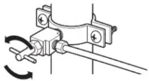
12 TURN ON THE WATER SUPPLY
natural_image
Mechanical clamp mechanism diagram showing rotational motion (no text or symbols)
Turn the water on at the shutoff valve (house water supply) and check for any leaks.
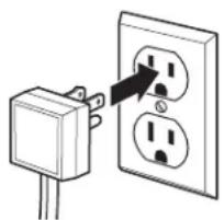
13 PLUG IN THE REFRIGERATOR
natural_image
Simple line drawing of an electrical outlet with two outlets and a plug (no text or symbols)
See the grounding information attached to the power cord.
14 LEVEL THE REFRIGERATOR
The leveling legs have 2 purposes:
- Leveling legs adjust so the refrigerator is firmly positioned on the floor and does not wobble.
- Leveling legs serve as a stabilizing brake to hold the refrigerator securely in position during operation and cleaning. The leveling legs also prevent the refrigerator from tipping.
A Turn the leveling legs clockwise to raise the refrigerator, counterclockwise to lower it.
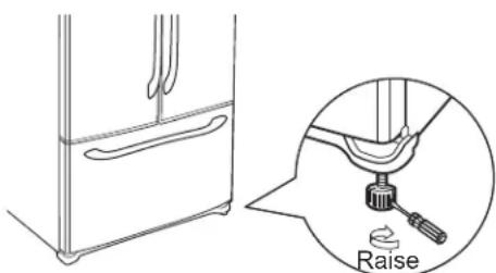
Flat-Head Screwdriver
NOTICE: To avoid possible property damage, the leveling legs must be firmly touching the floor.
15 LEVEL THE REFRIGERATOR DOORS
Remember a level refrigerator is necessary for getting the doors perfectly even. If you need help, review the previous section on leveling the refrigerator.
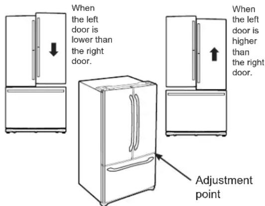
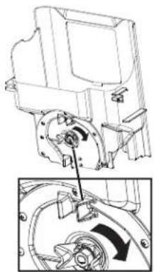
A If you open the freezer door, you can see the center hinge.
B Insert 1/4" Allen wrench into the shaft of the center hinge.
C Adjust the height by turning clockwise or counterclockwise. When you turn counterclockwise, the door will move up.
INSTALLING THE REFRIGERATOR (Cont.)
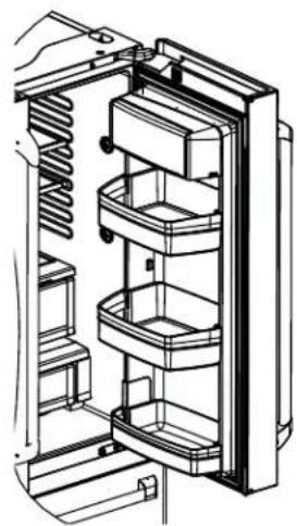
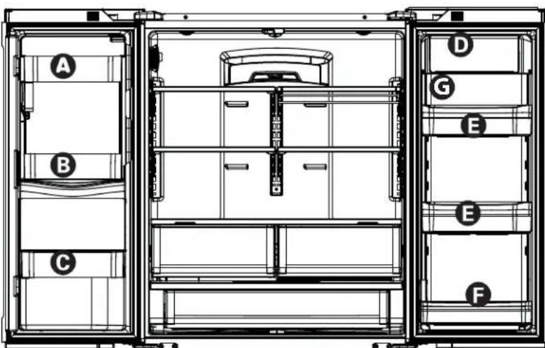
Non-Dispense Models
natural_image
Technical line drawing of a multi-level elevator cabinet with labeled components (no text or symbols)
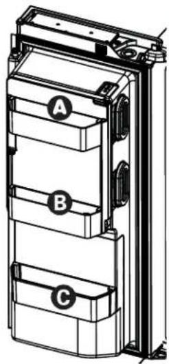
Refrigerator Assembly Instructions, suggested assembly.

natural_image
Technical line drawing of a multi-tiered electrical enclosure or enclosure unit with labeled components A, B, and C (no text or symbols beyond labels)
natural_image
Pure technical line drawing of a rectangular frame with corner brackets and base supports (no text or symbols)
natural_image
Diagram showing a mechanical assembly with an arrow indicating direction and a dashed line pointing to a component (no text or symbols present)
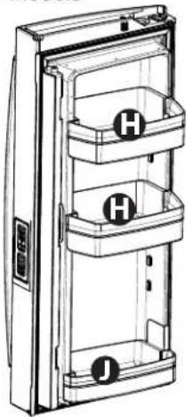
To place bins into doors:
1 Match your bin with the letter shown. Position the bin hooks over the bin locator and push forward until inserted fully.
natural_image
Technical line drawing of a curved mechanical component or bracket (no text or symbols)
Bin hook rear each side

2 Push bin down until locked into position.
Bin locator each side
natural_image
Pure technical line drawing of a mechanical component with no text or symbols
INSTALLING THE WATER LINE
BEFORE YOU BEGIN
Recommended copper water supply kits are WX8X2, WX8X3 or WX8X4, depending on the amount of tubing you need. Approved plastic water supply lines are SmartConnect™ Refrigerator Tubing (WX08X10006, WX08X10015 and WX08X10025).
When connecting your refrigerator to a Reverse Osmosis Water System, the only approved installation is with a RVKit. For other reverse osmosis water systems, follow the manufacturer's recommendations.
If the water supply to the refrigerator is from a Reverse Osmosis Water Filtration System (RO) AND the refrigerator also has a water filter, use the refrigerator's filter bypass plug. Using the refrigerator's water filtration cartridge in conjunction with an RO water filter can result in hollow ice cubes. Some models do not come equipped with the filter bypass plug. To obtain a free bypass plug, visit cafeappliances.com/service. In Canads, visit cafeappliances.ca/service.
This water line installation is not warranted by the refrigerator or ice maker manufacturer. Follow these instructions carefully to minimize the risk of expensive water damage.
Water hammer (water banging in the pipes) in house plumbing can cause damage to refrigerator parts and lead to water leakage or flooding. Call a qualified plumber to correct water hammer before installing the water supply line to the refrigerator.
To prevent burns and product damage, do not hook up the water line to the hot water line.
For LCD Models: If the refrigerator is operated before the water connection is made to the ice maker, see ICE MAKER under “settings” menu of the LCD Operations section and follow the screen commands to turn the ice maker OFF.
Do not install the ice maker tubing in areas where temperatures fall below freezing.
When using any electrical device (such as a power drill) during installation, be sure the device is double insulated or grounded in a manner to prevent the hazard of electric shock, or is battery powered.
All installations must be in accordance with local plumbing code requirements.
WHAT YOU WILL NEED
- Copper or SmartConnect™ Refrigerator Tubing kit, 1/4" outer diameter to connect the refrigerator to the water supply. If using copper, be sure both ends of the tubing are cut square.
To determine how much tubing you need: measure the distance from the water valve on the back of the refrigerator to the water supply pipe. Be sure there is sufficient extra tubing to allow the refrigerator to move out from the wall after installation.
SmartConnect™ Refrigerator Tubing Kits are available in the following lengths:
8' (2.4 m) - WX08X10006
15' (4.6 m) - WX08X10015
25' (7.6 m) - WX08X10025
WARNING
Connect to potable water supply only.
A cold water supply is required for automatic icemaker operation. The water pressure must be between 40 and 120 psi (275-827 kilopascals)
INSTALLING THE WATER LINE (Cont.)
WHAT YOU WILL NEED (Cont.)
NOTE: The only GE Appliances, a Haier company, approved plastic tubing is that supplied in SmartConnect™ Refrigerator Tubing kits. Do not use any other plastic water supply line because the line is under pressure at all times. Certain types of plastic will crack or rupture with age and cause water damage to your home.
- A water supply kit (containing tubing, shutoff valve and fittings listed below) is available at extra cost from your dealer or from cafeappliances.com/parts. In Canada, visit cafeappliances.ca/parts.
- A cold water supply. The water pressure must be between 20 and 120 p.s.i. (1.4–8.1 bar).
- Power drill.
- 1/2" or adjustable wrench.
- Straight and Phillips blade screwdriver.
- Two 1/4" outer diameter compression nuts and 2 ferrules (sleeves)—to connect the copper tubing to the shutoff valve and the refrigerator water valve.
OR
- If you are using a SmartConnect™ Refrigerator Tubing kit, the necessary fittings are preassembled to the tubing.

- If your existing copper water line has a flared fitting at the end, you will need an adapter (available at plumbing supply stores) to connect the water line to the refrigerator OR you can cut off the flared fitting with a tube cutter and then use a compression fitting. Do not cut formed end from SmartConnect™ Refrigerator tubing.
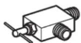
- Shutoff valve to connect to the cold water line. The shutoff valve should have a water inlet with a minimum inside diameter of 5/32" at the point of connection to the COLD WATER LINE. Saddle-type shutoff valves are included in many water supply kits. Before purchasing, make sure a saddle-type valve complies with your local plumbing codes.
Install the shutoff valve on the nearest frequently used drinking water line.
① SHUT OFF THE MAIN WATER SUPPLY
Turn on the nearest faucet long enough to clear the line of water.
② CHOOSE THE VALVE LOCATION
Choose a location for the valve that is easily accessible. It is best to connect into the side of a vertical water pipe. When it is necessary to connect into a horizontal water pipe, make the connection to the top or side, rather than at the bottom, to avoid drawing off any sediment from the water pipe.
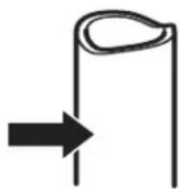
③ DRILL THE HOLE FOR THE VALVE
Drill a 1/4" hole in the water pipe (even if using a self-piercing valve), using a sharp bit. Remove any burrs resulting from drilling the hole in the pipe.
Take care not to allow water to drain into the drill.
Failure to drill a 1/4" hole may result in reduced ice production or smaller cubes.
natural_image
Simple line drawing of a mechanical component with a curved handle and threaded end (no text or symbols)
INSTALLING THE WATER LINE (Cont.)
④ FASTEN THE SHUTOFF VALVE
Fasten the shutoff valve to the cold water pipe with the pipe clamp.
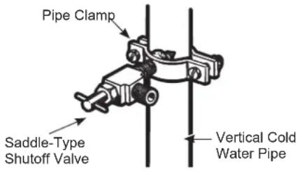
NOTE: Commonwealth of Massachusetts Plumbing Codes 248CMR shall be adhered to. Saddle valves are illegal and use is not permitted in Massachusetts. Consult with your licensed plumber.
5 TIGHTEN THE PIPE CLAMP
Tighten the clamp screws until the sealing washer begins to swell.
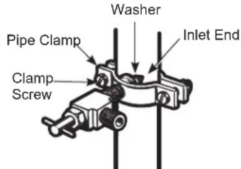
NOTE: Do not over tighten or you may crush the tubing.
6 ROUTE THE TUBING
Route the tubing between the cold water line and the refrigerator.
Route the tubing through a hole drilled in the wall or floor (behind the refrigerator or adjacent base cabinet) as close to the wall as possible.
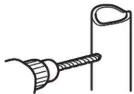
7 CONNECT THE TUBING TO THE VALVE
Place the compression nut and ferrule (sleeve) for copper tubing onto the end of the tubing and connect it to the shutoff valve.
Make sure the tubing is fully inserted into the valve. Tighten the compression nut securely.
For plastic tubing from a SmartConnect™ Refrigerator Tubing kit, insert the molded end of the tubing into the shutoff valve and tighten compression nut until it is hand tight, then tighten one additional turn with a wrench. Over tightening may cause leaks.
NOTE: Commonwealth of Massachusetts
Plumbing Codes 248CMR shall be adhered to.
Saddle valves are illegal and use is not permitted
in Massachusetts. Consult with your licensed
plumber.
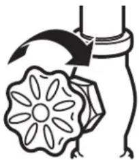
8 FLUSH OUT THE TUBING
Turn the main water supply on and flush out the tubing until the water is clear.
Shut the water off at the water valve after about one quart (1 liter), or 2 minutes, of water has been flushed through the tubing.
natural_image
Simple line drawing of a flower with a curved arrow above it, no text or symbols present.
To complete the installation of the refrigerator, go back to Step 11 in Installing the Refrigerator.
Newer refrigerators sound different from older refrigerators.
Modern refrigerators have more features and use newer technology.
Do you hear what I hear? These conditions are normal.
HUMMM...

WHOOSH...
■ The new high efficiency compressor may run faster and longer than your old refrigerator and you may hear a high-pitched hum or pulsating sound while it is operating.
■ You may hear a whooshing sound when the doors close. This is due to pressure equalizing within the refrigerator.
■ After dispensing ice, a motor will close the ice chute to keep warn room air from entering the ice bucket, maintaining ice at a freezing temperature.
The hum of the motor closing the ice chute is normal, shortly after dispensing ice.
WHIR!

- You may hear the fans spinning at high speeds. This happens when the refrigerator is first plugged in, when the doors are opened frequently or when a large amount of food is added to the refrigerator or freezer compartments. The fans are helping to maintain the correct temperatures.
■ The fans change speeds in order to provide optimal cooling and energy savings.
CLICKS, POPS, CRACKS and SNAPS
■ You may hear cracking or popping sounds when the refrigerator is first plugged in. This happens as the refrigerator cools to the correct temperature.
■ Expansion and contraction of cooling coils during and after defrost can cause a cracking or popping sound.
■ On models with an ice maker, after an ice making cycle, you may hear the ice cubes dropping into the ice bucket.
■ On models with a dispenser, during water dispense, you may hear the water lines move at initial dispense and after dispenser button is released.
WATER SOUNDS

■ The flow of refrigerant through the cooling coils may make a gurgling noise like boiling water.
■ Water dropping on the defrost heater can cause a sizzling, popping or buzzing sound during the defrost cycle.
■ A water dripping noise may occur during the defrost cycle as ice melts from the evaporator and flows into the drain pan.
■ Closing the door may cause a gurgling sound due to pressure equalization.
START UP COOLING
It can take up to 24 hours for the refrigerator and freezer temperatures to match the display. During that time refrigerator and freezer door openings should be minimized.
TIPS
■ Freezer cools first.
■ Refrigerator compartment cools last; it may take several hours after the freezer.
■ Turning off ice maker makes both fresh food and freezer food cool faster.
Troubleshooting Tips... Before you schedule service
Save time and money! Review the charts on the following pages first and you may not need to schedule service.
| Problem Possible Causes What to Do | | |
| Water filter indicated as installed incorrectly or a leak is present message on LCD screen. | Water filter installed backward or is leaking. | Check for leak. If no leak is present, remove filter/bypass plug, rotate 180° and reinstall. |
| Water filter indicator light remains lit after replacing filter. | Filter timer has not been reset or filter is installed backward. | Internal Dispense models:-Press and hold reset button for 3 secondsExternal Dispense models:-Remove filter and rotate 180° and reinstall. |
| Handle is loose/handle has a gap. | Handle needs adjusting See Attach Fresh Food Handle and Attach the Freezer Handle sections for detailed instructions. |
| Refrigerator beeping This is door alarm Turn off or disable with door closed. | If door open and alarm is sounding, you can only snooze the alarm. |
| Not cooling The cooling system is off See About Controls. | |
| Water has poor taste/odor Water dispenser has not been used for a long time | Dispense water, until all water in system is replenished. |
| Water in glass is warm Normal when refrigerator is first installed | Wait 24 hours for the refrigerator to completely cool down. |
| Water dispenser has not been used for a long time |
| Water system has drained Allow several hours for replenished supply to chill. |
| Water dispenser does not work Water supply line turned off or not connected | See Installing the Water Line. |
| Water filter clogged or filter/bypass plug not installed |
| Air may be trapped in the water system |
| Water in reservoir is frozen because the controls are set too cold |
| Water spurting from dispenser | Newly installed filter cartridge | Run cold water from the dispenser for 5 minutes (about 2 gallons).. |
| Water is leaking from dispenser Air may be present in the water line system, causing water to drip after being dispensed | Dispense water for at least 5 minutes to remove air from system |
| No water or ice cube production Supply line or shutoff valve is clogged | Call a plumber |
| Water filter is clogged |
| Filter cartridge not properly installed |
| Ice maker is turned off |
*Some models do not come equipped with the filter bypass plug. To obtain a free bypass plug, visit us on-line at cafeappliances.com/service. In Canads, visit cafeappliances.ca/service.
Troubleshooting Tips... Before you schedule service
| Problem Possible Causes What to | Do | |
| PRECISE FILL will not fill container | Normal, PRECISE FILL requires use of dispenser paddle | For a specific amount of water, select PRECISE FILL to dispense water |
| Photos not found | Photos not in root directory of USB | Make sure the photos are in the root directory in your USB |
| Photos not in JPEG format Photos must be in JPEG format |
| Camera/PC used with USB cord Must use a USB drive |
| Freezer cooling, fresh food not cooling | Normal, when refrigerator first plugged in or after extended power outage | Wait 24 hours for temperature in both compartments to reach selected temperatures. |
| Ice dispenser opens after closing freezer drawer | Normal The ice dispenser door may open after closing freezer door to allow access |
| Hot water does not work Operation disabled | Madel Make sure “Hot Water Disabled” is not selected |
| Low water pressure Make sure water line is not kinked |
| Water supply line turned off or not connected | See Installing the Water Line |
| Water filter clogged or filter/bypass plug not installed | Replace filter cartridge or remove filter and install bypass plug* |
| Hot water continues to dispense for a short time after releasing the knob | Water filter is partially clogged or low water pressure (<40 psi) | Replace filter cartridge or remove filter and install bypass plug* or increase water pressure |
| Difficult to open the Icebox door Icebox door gasket might stick to main door if it remains closed for a long duration | Disengage the door latch, wait for 3 minutes then open the Icebox door |
| Fresh food door not closing fully Fresh food door gasket may have unseated and interfering with articulating mullion operation | Reseat the gasket all the way in the groove |
| Low brewing flow rate There may have been a dent at the bottom of K-Cup causing the pin to pierce the filter allowing coffee grounds clogging the bottom pin | Avoid using damaged/dented K-cups, and clean the lower needle before next brew |
| Low brewing flow rate / water drips from inner door | Top needle of the brewer clogged | Unclog the top needle holes using a paper clip and rinse brewer. Rinse brewer after every use. |
| Brewer stuck in the door bracket | Dispenser is in hot water dispense mode instead of brew mode while the brew module is installed | Cancel hot water dispense mode so hot water tube will retract from the brew module |
| Brewer is not detected by the screen menu or hot water leaking from top of the brewer | Incorrect assembly of brewer in the bracket | Make sure the Keurig Logo is in the front. Push brewer all the way in the brackets |
| Coffee dispensed with splash or bubble bursting | Blocked vent hole in the brewer | Make sure the vent hole at the bottom of the brewer is clear from food or any other contamination |
| Beverage quality not as expected | You may be using non-standard or out dated K-Cups | Recommend using official Keurig K-cups that are not past expiration and have not been damaged |
| Liquid drips from the brewer after brewer cycle is completed and the brewer is removed from the bracket | It is possible for liquids to be retained by the brewer and drip when it is removed | Use a cloth or container to capture the drips when brewer is removed |
*Some models do not come equipped with the filter bypass plug. To obtain a free bypass plug, visit us on-line at cafeappliances.com/service. In Canads, visit cafeappliances.ca/service.
Troubleshooting Tips... Before you schedule service
| Problem Possible Causes What to | Do | |
| Delay when using Keurig K-cup Pod dispenser | To ensure a quality beverage is delivered, a short delay is required to ensure the refrigerator is operating correctly | Ensuring consistent, quality operation requires the refrigerator to delay dispense for a short period of time |
| After brewing, my powdered beverage is not fully cleared from the used pod | Depending on size selected, the powder may not dissolve fully. Some powdered beverages develop into ‘clumps’ when left sitting for some time | Shake the powdered pods before brewing to break up these clumps and allow better clearing. For powdered beverage with no filter, use the Cocoa cycle selection |
| Brewer lid is difficult to close K-cup is | not fully seated Press K-cup all the way down into the brewer prior to closing the lid. Lower needle must puncture K-cup before closing the brewer lid |
| Brewer leaks during the brew cycle T | trouble in closing brewer lid or damaged K-cup | Press K-cup all the way down into the brewer prior to closing the lid. Lower needle must puncture K-cup before closing the brewer lid. Recommend using official Keurig K-cups that have not been damaged and have a good seal between the top cover and plastic bottom |
SERVICE
Before you schedule service, review the detailed troubleshooting tips in the Owner's manual. If needed, service can be scheduled by visiting us online at cafeappliances.com/service. In Canada, visit cafeappliances.ca/service
Truth or Myth
| Truth or Myth? Answer Explanation | | |
| The refrigerator water filter may require replacement prior to six months of use | TRUE | The water filter indicator will indicate the need to replace the water filter every six months or 170 gallons (643.52 liters) of water dispensed (select models only). Water quality varies from city to city. If water flow from the dispenser slows, or ice production decreases, the water filter should be replaced, even though the filter indicator may not indicate the need for replacement. |
| The automatic ice maker in my refrigerator will produce ice when the refrigerator is plugged in to a power receptacle. | MYTH The refrigerator must be connected to water, and the ice maker must be turned on. Make sure the ice maker is turned on, only after the water line is connected and water is turned on. The ice maker can be turned on/off from the controls and ensure the ice maker is on, as indicated on the refrigerator control panel. See Automatic Ice Maker section. |
| After the refrigerator has been plugged in and connected to water, I will immediately have unlimited chilled water available from the water dispenser. | MYTH The water dispenser tank located inside the refrigerator stores water for dispensing. The water in this tank requires 24 hours to chill after installation. High usage conditions will not allow time for the water to chill. |
| After water dispenses, a few drops of water are normal. | TRUE A | few drops of water may fall from the dispenser, after the dispenser paddle has been released. To minimize the drops, remove the glass slowly from the dispenser. |
| I will never see frost inside the freezer compartment. | MYTH Frost inside the freezer typically indicates that the door is not properly sealed, or has been left open. If frost is found, clear the frost using a plastic spatula and towel, then check to ensure that no food packages or containers are preventing the freezer door from closing. Check the refrigerator control panel to ensure the door alarm is on. |
SERVICE
Before you schedule service, review the detailed troubleshooting tips in the Owner's manual. If needed, service can be scheduled by visiting us online at cafeappliances.com/service. In Canada, visit cafeappliances.ca/service
Truth or Myth
| Truth or Myth? Answer Explanation | | |
| When the refrigerator is installed, or after replacing the water filter, I must dispense water for five minutes. | TRUE | A newly installed refrigerator or water filter contains air in the water lines. Press the dispenser paddle and dispense cold water for at least 5 minutes to remove air from the water line, and flush the filter. |
| To fill the ice bucket to the maximum capacity, I should dispense 12 and 18 hours after installation. | TRUE | Dispensing 3-4 cubes 12 hours and 18 hours after installation, allows ice to disperse within the ice bucket, which in turns calls on the ice maker to produce additional ice. Normal ice production = 100 cubes in 24 hours. |
| I can use the water filter bypass plug to determine if the filter requires replacement. | TRUE Decrease in flow from the water dispenser, or decreased ice production, may indicate the need to replace the water filter. Install the water filter bypass plug (provided with the refrigerator on some models*), and check flow from the dispenser. If water flow returns to normal with the bypass plug in place, replace the water filter. |
| The top of the refrigerator doors will always be aligned. | MYTH Several things can affect the fresh food door alignment, including the floor the refrigerator is installed on and loading of doors. If the top of the fresh food doors are not aligned, use a 1/4" allen wrench to adjust the right/left hand door. The adjustment screw is located on the bottom right or left hand side of the door; open the freezer door to access the screw. |
| Refrigerator door handles can be easily tightened. | TRUE | If door handles are loose or have a gap, the handle can be adjusted using a 1/8" allen wrench, on set screws located on the ends of the handles. |
| There may be odor and taste problems with your ice. | TRUE After starting the ice maker throw away 24 hours of ice production to avoid odor and taste problems. |
| I can make fine adjustments to the fresh food doors to align them. | TRUE If the fresh food doors are not aligned, use a 1/4" Allen wrench to adjust the right hand door. The adjustment screw is located on the bottom of the right/left door. Open the freezer door to access. |
| Door handles should always be removed for installation. | MYTH Check chart on reverse side of this instruction. If the doors must be removed do not remove the handles, or if the refrigerator will fit easily through the passage way opening. Adjust handles that are loose or have a gap, by adjusting 1/8" set screws on either end of handles. |
| Door removal is always required for installation. | MYTH Check chart on reverse side of this instruction. Doors should only be removed when necessary to prevent damage from passage way or access to final location. |
| Refrigerator doors that won't close after installation, can be adjusted to close properly. | TRUE | Door mechanism works best if installed at 90°+. If installed at 180°, remove the door from the mid hinge, and swing the door 180° before reinstalling. See Reinstalling the Refrigerator Doors. |
| There is an adjustment to rear wheels. MYTH Front leveling legs are adjustable and should be used to balance the refrigerator. Leveling legs are used to make initial fresh food door adjustment. |
| Check for leaks after all water connections are made. | TRUE | While purging the air from the water system, check all water line connections for leaks. Check the connection to the household water supply at back of refrigerator, and door water line connect. |
| My LCD display will always be on when I plug the power cord in at installation. | MYTH If the refrigerator has been stored in a cold environment, the LCD may be slow to give a proper display. Give the refrigerator enough time to warm up, and the display should be okay. |
| Any packaging residue can be cleaned off the refrigerator using any cleaner. | MYTH Do not use wax, polish, bleach, or other products containing chlorine on Stainless Steel panels, door handles and trim. Check this instruction under "Cleaning the Outside" for full details. |
*Some models do not come equipped with the filter bypass plug. To obtain a free bypass plug, visit us on-line at cafeappliances.com/service. In Canads, visit cafeappliances.ca/service.
Café Refrigerator Limited Warranty
cafeappliances.com
All warranty service is provided by our Factory Service Centers, or an authorized service technician. To schedule service online, visit us at cafeappliances.com/service. Please have your serial number and your model number available when scheduling service. In Canada, visit cafeappliances.ca/service.
Servicing your refrigerator may require the use of the onboard data port for diagnostics. This gives a Café Factory Service technician the ability to quickly diagnose any issues with your appliance and helps Café improve its products by providing Café with information on your appliance. If you do not want your appliance data to be sent to Café, please advise your technician NOT to submit the data to Café at the time of service.
| For the Period of: Café | Will Replace |
| One YearFrom the date of the original purchase | Any part of the refrigerator which fails due to a defect in materials or workmanship. During the limited one-year warranty, Café will also provide, free of charge, all labor and related service to replace the defective part. |
| Thirty Days (Water filter, if included) From the original purchase date of the refrigerator | Any part of the water filter cartridge which fails due to a defect in materials or workmanship. During this limited thirty-day warranty, Café will also provide, free of charge, a replacement water filter cartridge. |
| Five Years From the date of the purchase | Any part of the sealed refrigerating system (the compressor, condenser, evaporator an all connecting tubing) which fails due to a defect in materials or workmanship. During this limited five-year sealed refrigerating system warranty, Café will also provide, free of charge, all labor and related service to replace the defective part in the sealed refrigerating system. |
What Café Will Not Cover:
■ Service trips to your home to teach you how to use the product.
■ Improper installation, delivery or maintenance.
■ Failure of the product if it is abused, misused, or used for other than the intended purpose or used commercially.
■ Loss of food due to spoilage.
■ Replacement of house fuses or resetting of circuit breakers.
■ Damage to finish, such as surface rust, tarnish, or small blemishes not reported within 48 hours of delivery.
■ Replacement of the water filter cartridge, if included, due to water pressure that is outside the specified operating range or due to excessive sediment in the water supply.
■ Replacement of the light bulbs, if included, or water filter cartridge, if included, other than as noted above.
■ Damage to the product caused by accident, fire, floods or acts of God.
■ Incidental or consequential damage caused by possible defects with this appliance.
■ Product not accessible to provide required service.
■ Damage caused by a non-GE Appliances Brand water filter.
EXCLUSION OF IMPLIED WARRANTIES
Your sole and exclusive remedy is product repair as provided in this Limited Warranty. Any implied warranties, including the implied warranties of merchantability or fitness for a particular purpose, are limited to one year or the shortest period allowed by law.
For US Customers: This limited warranty is extended to the original purchaser and any succeeding owner for products purchased for home use within the USA. If the product is located in an area where service by a Café Authorized Servicer is not available, you may be responsible for a trip charge or you may be required to bring the product to an Authorized Café Service location for service. In Alaska, the limited warranty excludes the cost of shipping or service calls to your home.
Some states do not allow the exclusion or limitation of incidental or consequential damages. This limited warranty gives you specific legal rights, and you may also have other rights which vary from state to state. To know what your legal rights are, consult your local or state consumer affairs office or your state's Attorney General.
Warrantor: GE Appliances, a Haier company
Louisville, KY 40225
For Customers in Canada: This limited warranty is extended to the original purchaser and any succeeding owner for products purchased in Canada for home use within Canada. In-home warrant service will be provided in areas where it is available and deemed reasonable by Mabe to provide.
Warrantor Canada: MC Commercial, Inc., Burlington, Ontario, L7R 5B6
RPWFE Water Filter Cartridge Limited Warranty
Contact us at cafeappliances.com/parts
Staple your receipt here. Proof of the original purchase date is needed to obtain service under the warranty.
For The Period Of: We Will Replace, At No Charge To You:
Thirty Days
From the date of the original purchase
Any part of the water filter cartridge which fails due to a defect in materials or workmanship during this limited thirty-day warranty.*
What is Not Covered:
• Service trips to your home to teach you how to use the product.
- Improper installation.
- Failure of the product if it is abused, misused, used for other than the intended purpose or used commercially.
- Replacement of house fuses or resetting of circuit breakers.
- Replacement of the water filter cartridge due to water pressure that is outside the specified operating range or due to excessive sediment in the water supply.
- Damage to the product caused by accident, fire, floods or acts of God.
- Incidental or consequential damage caused by possible defects with this appliance.
This warranty is extended to the original purchaser and any succeeding owner for products purchased for home use within the U.S.A. In Alaska, the warranty excludes the cost of shipping or service calls to your home.
Some states do not allow the exclusion or limitation of incidental or consequential damages. This warranty gives you specific legal rights, and you may also have other rights which vary from state to state. To know what your legal rights are, consult your local or state consumer affairs office or your state's Attorney General.
For Purchases Made In Iowa: This form must be signed and dated by the buyer and seller prior to the consummation of this sale.
This form should be retained on file by the seller for a minimum of two years.
Buyer:
| Name |
| Address |
| City State Zip |
| Signature Date |
Seller:
| Name |
| Address |
| City State Zip |
| Signature Date |
*If your part fails because of a manufacturing defect within thirty days from the date of original purchase for use, we will give you a new or, at our option, a rebuilt part without charge. Return the defective part to the parts supplier from whom it was purchased together with a copy of the "proof of purchase" for the part. If the part is defective and shows no signs of abuse, it will be exchanged. The warranty does not cover the failure of parts which are damaged while in your possession, are abused, or have been installed improperly. It does not cover the cost of returning the part to the supplier from whom it was purchased nor does it cover the cost of labor to remove or install it to diagnose the fault. It does not cover parts used in products in commercial use except in the case of air conditioning equipment. In no event shall GE Appliances, a Haier company, be liable for consequential damages.
Warrantor: GE Appliances, a Haier company
EXCLUSION OF IMPLIED WARRANTIES: Your sole and exclusive remedy is part exchange as provided in this Limited Warranty. Any implied warranties, including the implied warranties of merchantability or fitness for a particular purpose, are limited to six months or the shortest period allowed by law.
Filter Model: RPWFE
Use Replacement Cartridge RPWFE.
The concentration of the indicated substances in water entering the system was reduced to a concentration less than or equal to the permissible limit for water leaving the system as specified in NSF/ANSI Standard 42 and Standard 53. System tested and certified by NSF International against NSF/ANSI Standard 42 and Standard 53 for the reduction of substances listed below.
Capacity 170 Gallons (643.5 Liters). Contaminant Reduction Determined by NSF testing.
| Substance Tested for Reduction | Average Influent | NSF specified Challenge Concentration | Avg % Reduction | Average Product Water Concentration | Max Permissible Product Water Concentration | NSF Reduction Requirements | NSF Test Report |
| Chlorine Taste and Odor | 2.0 mg/L | 2.0 mg/L ± 10% | 97.4% | 0.05 mg/L | N/A | ≥50% | J-00102044 |
| Nominal Particulate Class I, ≥0.5 to < 1.0 μm | 7,633,333 pts/mL | At least 10,000 particles/mL | 99.0% | 71,850 pts/ml | N/A | ≥85% | J-00106249 |
| Asbestos | 109 MFL | 10^7 to 10^8 fibers/L; fibers greater than 10μm in length | 99.99% | <1 MFL | N/A | ≥99% | J-00102069 |
| Atrazine | 0.009 mg/L | 0.009 mg/L ± 10% | 94.4% | 0.0005 mg/L | 0.003 mg/L | N/A | J-00102058 |
| Benzene | 0.016 mg/L | 0.015 mg/L ± 10% | 96.4% | 0.001 mg/L | 0.005 mg/L | N/A | J-00102065 |
| Carbofuran | 0.08 mg/L | 0.08 mg/L ± 10% | 98.8% | 0.001 mg/L | 0.04 mg/L | N/A | J-00102059 |
| Cyst* | 104,750 cysts/L | Minimum 50,000 cysts/L | 99.99% | 3 cyst/L | N/A | ≥99.95% | J-00102057 |
| Lead pH @6.5 | 0.140 mg/L | 0.15 mg/L ± 10% | 99.3% | 0.001 mg/L | 0.010 mg/L | N/A | J-00102052 |
| Lead pH @8.5 | 0.158 mg/L | 0.15 mg/L ± 10% | 98.3% | 0.002 mg/L | 0.010 mg/L | N/A | J-00102053 |
| Mercury @ pH 6.5 | 0.006 mg/L | 0.006 mg/L ± 10% | 91% | 0.0003 mg/L | 0.002 mg/L | N/A | J-00102054 |
| Mercury @ pH 8.5 | 0.006 mg/L | 0.006 mg/L ± 10% | 88.3%% | 0.0007 mg/L | 0.002 mg/L | N/A | J-00104087 |
| Lindane | 0.002 mg/L | 0.002 mg/L ± 10% | 99% | 0.00002 mg/L | 0.0002 mg/L | N/A | J-00102063 |
| P-Dichlorobenzene | 0.222 mg/L | 0.225 mg/L ± 10% | 99.8% | 0.0005 mg/L | 0.075 mg/L | N/A | J-00102067 |
| Toxaphene | 0.015 mg/L | 0.015 mg/L ± 10% | 93.5% | 0.001 mg/L | 0.003 mg/L | N/A | J-00102061 |
| 2, 4-D Reduction | 0.218 mg/L | 0.210 mg/L±10% | 99.9% | 0.0001 mg/L | 0.07 mg/L | N/A | J-00102064 |
| VOC | 0.278 mg/L | 0.300 mg/L ± 10% | 97.7% | 0.0015 mg/L | N/A | ≥95% | J-00102070 |
*Based on the use of Cryptosporidium parvum oocysts.
The following pharmaceutical reduction claims have not been certified by NSF International. Claims tested and verified by independent laboratory:
| Substance Reduction Average Influent | | NSF specified Challenge Concentration | Avg % Reduction | Average Product Water Concentration | Max Permissible Product Water Concentration | NSF Test Report |
| Atenolol | 1088 ng/L | N/A | 99.5% | 5.0 ng/L | N/A | J-00103221 |
| Fluoxetine | 845 ng/L | N/A | 99.4% | 5.0 ng/L | N/A | J-00103221 |
| Ibuprofen | 898 ng/L | N/A | 98.8% | 9.9 ng/L | N/A | J-00103726 |
| Progesterone | 945 ng/L | N/A | 99.4% | 5.5 ng/L | N/A | J-00103727 |
| Trimethoprim | 403 ng/L | N/A | 99.5% | 2.0 ng/L | N/A | J-00103221 |
Application Guidelines/Water Supply Parameters
| Service Flow | 0.5 gpm (1.89 lpm) | Water Pressure 25-120 psi (172–827 kPa) |
| Water Supply | Potable Water | Water Temperature | 33°F - 100°F (0.6°C - 38°C) |
It is essential that the manufacturer's recommended installation, maintenance and filter replacement requirements be carried out for the product to perform as advertised. See Installation Manual for Warranty information.
NOTE: While the testing was performed under standard laboratory conditions, actual performance may vary.
Replacement Cartridge: RPWFE. For estimated costs of replacement elements visit our website at cafeappliances.com/parts.
WARNING
To reduce the risk associated with ingestion of contaminants:
- Do not use with water that is microbiologically unsafe or of unknown quality without adequate disinfection before and after the system. Systems certified for cyst reduction may be used on disinfected water that may contain filterable cysts. EPA Establishment Number 070595-MEX-001.
NOTICE
To reduce the risk of water leakage or flooding, and to ensure optimal filter performance:
- Read and follow use instructions before installation and use of this system.
- Installation and use MUST comply with all state and local plumbing codes.
- Do not install if water pressure exceeds 120 psi (827 kPa). If your water pressure exceeds 80 psi (552 kPa), you must install a pressure-limiting valve. Contact a plumbing professional if you are uncertain how to check your water pressure.
- Do not install where water hammer conditions may occur. If water hammer conditions exist you must install a water hammer arrester. Contact a plumbing professional if you are uncertain how to check for this condition.
- Do not install on hot water supply lines. The maximum operating water temperature of this filter system is 100^ (38°C).
- Protect filter from freezing. Drain filter when temperatures drop below 33°F (0.6°C).
- Change the disposable filter cartridge every six months or sooner if you observe a noticeable reduction in water flow rate.
- Failure to replace the disposable filter cartridge at recommended intervals may lead to reduced filter performance and cracks in the filter housing, causing water leakage or flooding.

Tested and certified by NSF International against NSF/ANSI Standard 42 and Standard 53 in model GE Appliances RPWF and GE Appliances RPWFE for the reduction of the claims specified on the performance data sheet.
RPWFE
Consumer Support
Café Website
Have a question or need assistance with your appliance? Try the Café website 24 hours a day, any day of the year! You can also shop for more great Café products and take advantage of all our on-line support services designed for your convenience. In the US: cafeappliances.com
Register Your Appliance
Register your new appliance on-line at your convenience! Timely product registration will allow for enhanced communication and prompt service under the terms of your warranty, should the need arise. You may also mail in the pre-printed registration card included in the packing material. In the US: cafeappliances.com/register
Schedule Service
Expert Café repair service is only one step away from your door. Get on-line and schedule your service at your convenience any day of the year. In the US: cafeappliances.com/service
Extended Warranties
Purchase a Café extended warranty and learn about special discounts that are available while your warranty is still in effect. You can purchase it on-line anytime. Café Service will still be there after your warranty expires.
In the US: cafeappliances.com/extended-warranty
Remote Connectivity
For assistance with wireless network connectivity (for models with remote enable), visit our website at cafeappliances.com/connect
Parts and Accessories
Individuals qualified to service their own appliances can have parts or accessories sent directly to their homes (VISA, MasterCard and Discover cards are accepted). Order on-line today 24 hours every day.
In the US: cafeappliances.com/parts
Instructions contained in this manual cover procedures to be performed by any user. Other servicing generally should be referred to qualified service personnel. Caution must be exercised, since improper servicing may cause unsafe operation.
If you are not satisfied with the service you receive from Café, contact us on our website with all the details including your phone number, or write to:
In the US: General Manager, Customer Relations | Café Appliances, Appliance Park | Louisville, KY 40225 cafeappliances.com/contact
CAFÉ
flowchart
graph TD
    A["Refrigerator rated 25°C for 70°C"] --> B["Recommended: 25°C"]
    B --> C["Actual Set -88°F"]
    C --> D["Energy Smart"]
    D --> E["Recommended: 0°F"]
    E --> F["Freezer Energy Smart Control at 3 Seconds"]
    G["Door Alarm"] --> H["Ice Maker"]
    H --> I["Lock Controls at 3 Seconds"]
    I --> J["Reset Filter at 3 Seconds"]
natural_image
Simple line drawing of a vertical line and a curved container with a black dot (no text or symbols)
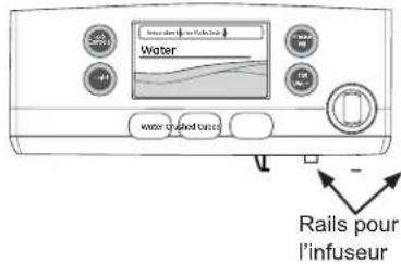

WiFi Connect Enabled\*
natural_image
Simple line drawing of a door with a circular component and an arrow pointing to it (no text or symbols)
Connected Appliance Information
Contains FCCID: ZKJ-WCATA003
Network: GE_MODULE_XXXX
Contains IC: 10229A-WCATA003
Password: XXXXXXXXX
MAC ID: D8-28-C9-XXXXXXXXX
PT. NO. 257C2110G001
RENSEIGNEMENTS RÉGLEMENTAIRES
natural_image
Line drawing of hands holding a rectangular tray or tray with a grid pattern, no text or symbols present
Clayette QuickSpace\*
natural_image
Line drawing of a hand pressing down on a laptop screen with an arrow indicating the next page (no text or symbols present)
natural_image
Technical line drawing of a mechanical device with no visible text or symbols
natural_image
Technical line drawing of a mechanical assembly or bracket (no text or symbols)
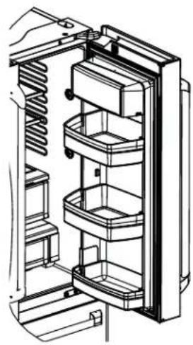
natural_image
Technical line drawing of an open refrigerator with internal compartments and handlebars (no text or symbols)
natural_image
Technical line drawing of a multi-tiered mechanical or electrical enclosure with no visible text or symbols
natural_image
Technical line drawing of a refrigerator with three shelves and door (no text or symbols)
natural_image
Technical line drawing of a mechanical assembly with no visible text or symbols
natural_image
Technical line drawing of a mechanical assembly with a perforated component inserted into a housing (no text or symbols)
natural_image
Technical line drawing of an internal storage or rack system with numbered components (no text or symbols)
natural_image
Technical line drawing of a server rack with ventilation slots and directional arrows indicating movement (no text or symbols)
natural_image
Technical line drawing of a mechanical assembly with a close-up view showing internal components (no text or symbols)
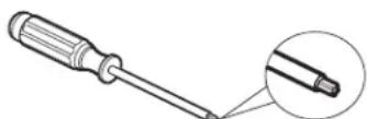
Tournevis Torx T20, T25
natural_image
Line drawing of a mechanical component with multiple spring-like grooves and a central rectangular block (no text or symbols)
natural_image
Line drawing of hands assembling or adjusting a mechanical component (no text or symbols visible)
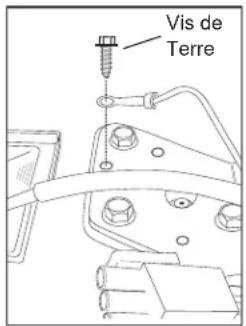
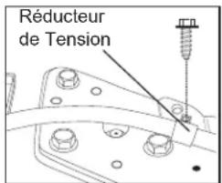
natural_image
Pure mechanical assembly diagram without any text, numbers, or symbols
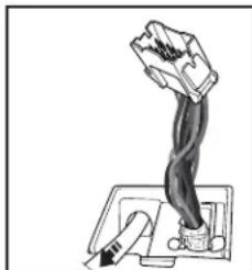
natural_image
Illustration of a hand gripping a mechanical lever with a handle (no text or symbols)
natural_image
Technical line drawing of a mechanical bracket with two screws inserted (no text or symbols)
ATTENTION
natural_image
Mechanical assembly diagram showing a bracket with mounting holes and a downward arrow indicating motion (no text or symbols)
natural_image
Technical line drawing of a mechanical assembly with an inset close-up showing internal components (no text or symbols)
ATTENTION
natural_image
Technical line drawing of a mechanical device with an upward arrow indicating motion (no text or symbols present)
ATTENTION
natural_image
Technical line drawing of a mechanical assembly with an inset close-up showing a component detail (no text or symbols)
natural_image
Technical line drawing of a mechanical assembly with no visible text or symbols
9 MISE À NIVEAU DE LA PORTE DU CONGÉLATEUR (suite)
natural_image
Diagram of a mechanical device with rotating components and directional arrows indicating motion (no text or symbols)
0 - Position initiale
1 – Lever de 0,050 po
-1 - Abaisser de 0,050 po
-2 - Abaisser de 0,100 po
-3 - Abaisser de 0,150 po
AVOIR BESOIN (non inclus)
Tire-fond 14 po (6 mm) x 112 po (38 mm)
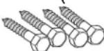
natural_image
Simple line drawing of an electrical outlet with a plug and socket (no text or symbols)
14 MISE À NIVEAU DU RÉFRIGÉRATEUR
natural_image
Technical line drawing of a multi-level elevator cabinet with labeled components (no text or symbols present)
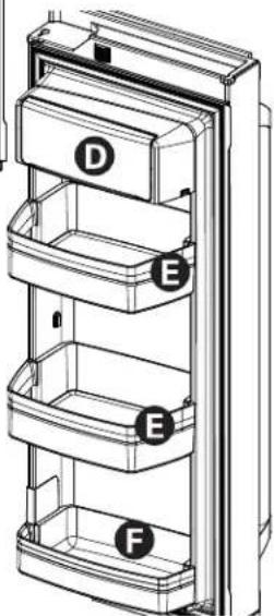
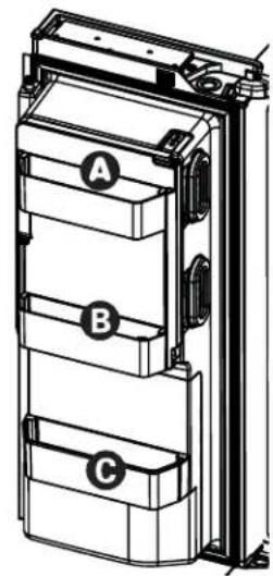
natural_image
Technical line drawing of a multi-tiered mechanical or electrical enclosure with labeled components A, B, and C (no text or symbols beyond labels)
natural_image
Diagram showing a mechanical assembly with an arrow and dashed line indicating a connection or alignment (no text or symbols present)
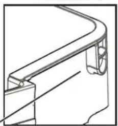
natural_image
Technical line drawing of a mechanical component with curved and straight sections (no text or symbols)
natural_image
Technical line drawing of a mechanical bracket or mounting detail with a small inset detail (no text or symbols)
INSTALLATION DE LA CONDUITE D'EAU
AVANT DE COMMENCER
natural_image
Simple line drawing of a mechanical joint or bracket (no text or symbols)
INSTALLATION DE LA CONDUITE D'EAU (suite)
4 FIXATION DU ROBINET D'ARRÊT
natural_image
Simple line drawing of a flower with petals and a curved arrow, no text or symbols present
Garant Canada: MC Commercial, Inc., Burlington, Ontario, L7R 5B6
Au Canada : cafeappliances.ca
Au Canada : cafeappliances.ca/register
Au Canada : cafeappliances.ca/service
Prolongation de garantie
Au Canada : cafeappliances.ca/service
Au Canada : cafeappliances.ca
cafeappliances.com/contact
Au Canada : Director, Consumer Relations, Mabe Canada Inc. | Suite 310, 1 Factory Lane | Moncton, N.B. E1C 9M3 cafeappliances.ca/contact
CAFÉ
natural_image
Technical line drawing of a door lock assembly with a door handle and control panel (no text or symbols)
natural_image
Simple line drawing of a vertical line and a vertical container with a black dot (no text or symbols)
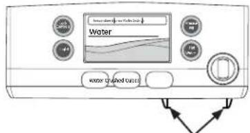
Rieles de la
cafeteria

Elija el tamaño.

natural_image
Simple line drawing of a door with a circular component and an arrow pointing to it (no text or symbols)
Connected Appliance Information
Contains FCCID: ZKJ-WCATA003
Network: GE_MODULE_XXXX
Contains IC: 10229A-WCATA003
Password: XXXXXXXXX
MAC ID: D8-28-C9-XXXXXXXXX
PT. NO. 257C2110G001
Para reemplazar:
natural_image
Line drawing of hands holding a rectangular object with vertical supports (no text or symbols)
Estante Quick Space\*
natural_image
Line drawing of a hand pressing down on a laptop screen with an arrow indicating the next page (no text or symbols present)
Recipiente de Lácteos No Ajustable\*
natural_image
Technical line drawing of a mechanical device with no visible text or symbols
natural_image
Technical line drawing of a mechanical device with no visible text or symbols

natural_image
Technical line drawing of an open refrigerator with internal compartments (no text or labels)
natural_image
Technical line drawing of a multi-tiered mechanical or electrical enclosure with no visible text or symbols
natural_image
Technical line drawing of a refrigerator internal compartments (no text or symbols)
natural_image
Technical line drawing of a mechanical assembly with no visible text or symbols
natural_image
Technical line drawing of a mechanical assembly with a component inserted into a housing (no text or symbols)
natural_image
Technical line drawing of a server rack with ventilation slots and mounting brackets (no text or symbols)
natural_image
Technical line drawing of a mechanical assembly with a close-up view showing internal components (no text or symbols)
natural_image
Pure technical line drawing of a mechanical component with no text or symbols
natural_image
Line drawing of hands assembling or adjusting a mechanical component (no text or symbols visible)
natural_image
Pure mechanical assembly diagram without any text, numbers, or symbols
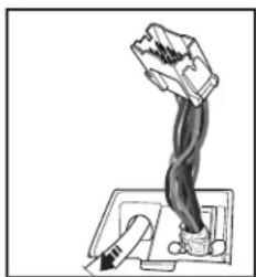
natural_image
Simple line drawing of a hand gripping a lever, with no text or symbols present.
natural_image
Technical line drawing of a mechanical bracket with two screws inserted (no text or symbols)
PRECAUCIÓN
natural_image
Mechanical assembly diagram showing a bracket with mounting holes and a cylindrical component (no text or symbols)
natural_image
Technical line drawing of a mechanical assembly with an inset close-up showing internal components (no text or symbols)
▲PRECAUCIÓN
natural_image
Technical line drawing of a mechanical assembly with no visible text or symbols
natural_image
Technical line drawing of a mechanical assembly with an inset close-up showing a component detail (no text or symbols present)
natural_image
Technical line drawing of a mechanical assembly with no visible text or symbols
natural_image
Illustration of a mechanical device with motion arrows indicating rotation or movement (no text or symbols)
0 - Posición inicial
1 - Levante de a 0.127 cm (0.050")
-1 - Baje de a 0.127 cm (0.050")
-2 - Baje de a 0.254 cm (0.100")
-3 - Baje de a 0.381 cm (0.150")
1/4" (6 mm) x 1-1/2" (38 mm)
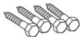
Casquillos de Anclaje
natural_image
Mechanical assembly diagram showing a lever mechanism with rotating arrows (no text or symbols)
13 ENCHUFE EN EL REFRIGERADOR
natural_image
Simple line drawing of an electrical outlet with a plug and socket (no text or symbols)
natural_image
Technical line drawing of a multi-level refrigerator with labeled compartments (no text or symbols)
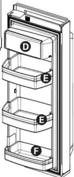

natural_image
Technical line drawing of a multi-tiered electrical enclosure or enclosure unit with labeled components A, B, and C (no text or symbols beyond labels)
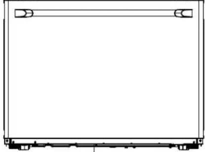
natural_image
Pure technical line drawing of a rectangular frame with corner brackets and base supports (no text or symbols)
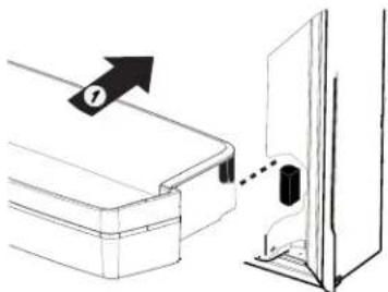
natural_image
Diagram showing a door with a lock and a dashed line indicating a connection point (no text or symbols present)
natural_image
Technical line drawing of a curved mechanical component or bracket (no text or symbols)
natural_image
Technical line drawing of a mechanical bracket or mounting detail with a small inset detail (no text or symbols)
natural_image
Simple line drawing of a mechanical component with a threaded end and curved top (no text or symbols)
CÓMO INSTALAR LA TUBERÍA DE AGUA (Cont.)
④ AJUSTE LA VÁLVULA DE CIERRE
natural_image
Simple line drawing of a flower with a curved arrow above it, no text or symbols present
Warrantor: GE Appliances, a Haier company
Louisville, KY 40225

