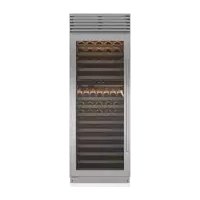
BW30SPHRH - Fridge Sub-Zero - Free user manual and instructions
Find the device manual for free BW30SPHRH Sub-Zero in PDF.



User questions about BW30SPHRH Sub-Zero
0 question about this device. Answer the ones you know or ask your own.
Ask a new question about this device
Download the instructions for your Fridge in PDF format for free! Find your manual BW30SPHRH - Sub-Zero and take your electronic device back in hand. On this page are published all the documents necessary for the use of your device. BW30SPHRH by Sub-Zero.
USER MANUAL BW30SPHRH Sub-Zero
Wine Storage Installation Guide

Contents
3 Wine Storage
4 Model UW-24 / UW-24FS Site Preparation
6 Model UW-24 / UW-24FS Installation
10 Model BW-30 Site Preparation
16 Model BW-30 Installation
Features and specifications are subject to change at any time without notice. Visit subzero.com/specs for the most up-to-date information.
Important Note
To ensure this product is installed and operated as safely and efficiently as possible, take note of the following types of highlighted information throughout this guide:
IMPORTANT NOTE highlights information that is especially important.
CAUTION indicates a situation where minor injury or product damage may occur if instructions are not followed.
WARNING states a hazard that may cause serious injury or death if precautions are not followed.
IMPORTANT NOTE: Throughout this guide, dimensions in parentheses are millimeters unless otherwise specified.
IMPORTANT NOTE: Save these instructions for the local electrical inspector.
Product Information
Important product information including the model and serial number are listed on the product rating plate. The rating plate is located on the underside of the control panel, on the left. Refer to the illustrations below.
If service is necessary, contact Sub-Zero factory certified service with the model and serial number. For the name of the nearest Sub-Zero factory certified service or for questions regarding the installation, visit the contact & support section of our website, subzero.com or call Sub-Zero customer care at 800-222-7820.
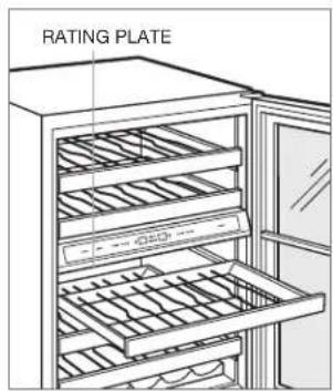
Models UW-24 and UW-24FS.
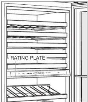
Model BW-30.
Tools and Materials
Screwdrivers-standard, Phillips and Torx.
- Powerdrill.
- Drill bits (masonry bits required for concrete installation).
- Standard socket and wrench set.
2' and 4' levels.
- Material to protect home, flooring and cabinetry during installation.
Opening Dimensions
MODEL UW-24
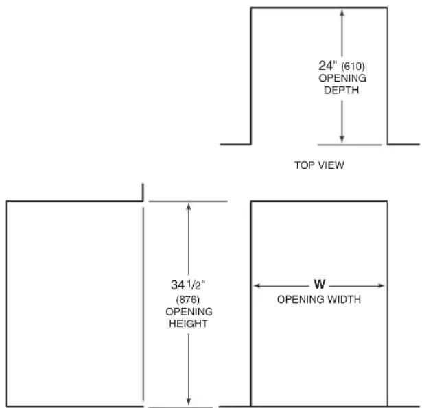
SIDE VIEW FRONT VIEW
OPENINGWIDTHW
UW-24 24"
(610)
DUAL OPENINGWIDTH W
Two 24" (610) Models 48
1/8" (1222)
Dual installation kit required.
DUAL INSTALLATION
If two units are installed side by side, a dual installation kit may be required. Installations without a custom filler strip require a dual installation kit. If a dual installation kit is not specified, a 2^ (51) filler strip is recommended between units. Dual installations without a filler strip can only be accomplished using two units with opposite hinges. Refer to the illustrations below.
Dual installation kits are available through an authorized Sub-Zero dealer. For local dealer information, visit the find a showroom section of our website, subzero.com. For questions regarding the installation, call Sub-Zero customer care at 800-222-7820.
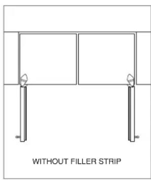
Opposite hinges.
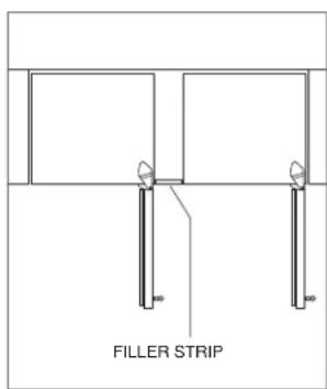
Same side hinges.
Electrical
Installation must comply with all applicable electrical codes.
The electrical supply should be located within the shaded area shown in the illustration below. A separate circuit, servicing only this appliance is required. A ground fault circuit interrupter (GFCI) is not recommended and may cause interruption of operation.
IMPORTANT NOTE: The electrical outlet must be placed so the grounding prong is to the right of the thinner blades. The outlet must be flush with the back wall.
ELECTRICAL REQUIREMENTS
Electrical Supply 115 VAC, 60 Hz
Service 15 amp
Receptacle 3-prong grounding-type
WARNING
Do not use an extension cord, two-prong adapter or remove the power cord ground prong.
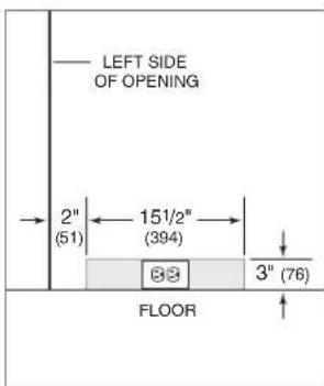
Electrical supply location.
Preparation
To operate properly, the door must open a minimum of 90^ . Use a minimum 3" (76) filler in corner installations to assure a 90^ door opening.
Uncrate the unit and inspect for damage. Remove and recycle packing materials. Do not discard the kickplate, antitip bracket, hardware and the leveling legs which hold the wood base to the bottom of the unit.
Anti-Tip Bracket
WARNING
To prevent the unit from tipping forward, the anti-tip bracket must be installed.
MODEL UW-24
The anti-tip bracket should be attached to the wall behind the unit with the bracket flange located 1/4 (6) above the top of the unit. Refer to the illustration below. Failure to properly position the anti-tip bracket will prevent proper engagement.
For installations that cannot accommodate the anti-tip bracket, a countertop bracket is provided to secure the unit to the countertop. Refer to the illustration below.
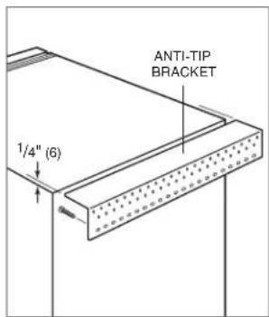
Anti-tip bracket (UW-24).
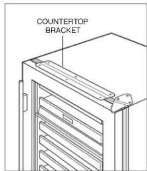
Countertop bracket.
Anti-Tip Bracket
MODEL UW-24FS
The back of the anti-tip bracket must be installed 24^5 / 8 (625) from the front and centered behind the unit. Refer to the illustration below. Refer to page 16 for wood and concrete floor applications.
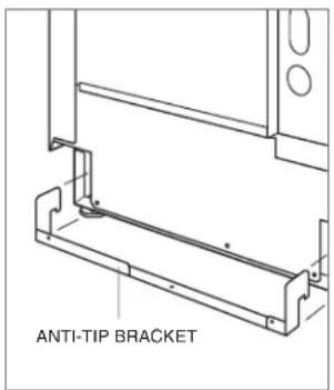
Anti-tip bracket (UW-24FS).
Custom Panel
MODEL UW-24
For overlay applications, a custom door panel must be installed. Panel size is critical for a proper fit. To verify panel requirements and dimensions, refer to the Sub-Zero design guide at subzero.com/specs.
Finish all sides of the custom panel. They may be visible when the door is open or through the glass door.
The custom overlay door panel is attached using screws provided, through the door frame. Screw locations are marked on the back of the custom panel using tenon centers inserted into holes of the door frame.
With the unit secured and door closed, hold the custom panel in desired position on the door. Lightly tap the front of the panel to locate mounting positions. Remove tenon centers. Refer to the illustration below.
The door frame has mounting holes to accommodate Sub-Zero accessory handles. If handle mounting holes are not utilized, the handle should be attached to the custom panel prior to mounting. Screw heads may need to be countersunk into the panel for proper alignment.
To mount the custom panel, open the door and use predrilled holes to position the panel. Drive screws into the panel through black tape on the door frame. Screw holes are hidden behind the door gasket. Use as many screws as necessary to secure the custom panel. Refer to the illustration below.
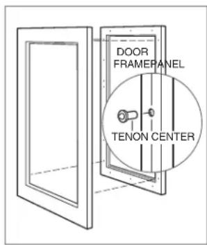
Tenon center.
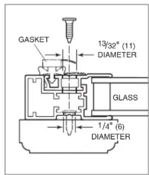
Door frame cross section.
Custom Panel
Adjustments can be made to the custom panel with a few mounting screws in place, but not fully tightened. Once the proper position is achieved, install and secure all screws.
Cover holes on the inside of the door frame with the cover patches or plugs provided.
CAUTION
A solid panel cannot be installed over the glass door. A solid door is available through an authorized Sub-Zero dealer. For local dealer information, visit the find a showroom section of our website, subzero.com.
Placement
CAUTION
Before moving the unit into position, secure the door closed and protect any finished flooring.
Use an appliance dolly to move the unit near the opening.
If the unit has been on its back or side, it must stand upright for a minimum of 24 hours before connecting power.
If the unit will be connected to a home security system, run lead wires through the compressor compartment prior to positioning the unit. Refer to page 8. Once the unit is in position, wiring connection can be completed from the front.
Leveling
Level the unit before sliding it into position. Turn each of the four leveling legs clockwise to raise the unit and counterclockwise to lower. Refer to the illustration below.
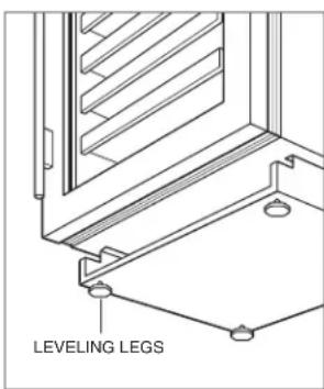
Leveling.
Completion
Plug the power cord into the grounded outlet, then slide the unit into position. Verify the anti-tip bracket is properly engaged.
It may be necessary to install the unit 1/4'' (6) beyond the front surface of adjacent cabinetry, to prevent interference when the door is opened to 145^ . Refer to the full-scale template on page 9.
HOME SECURITY CONNECTION
If the unit will be connected to a home security system, make connections to the leads shown in the illustration below. Refer to the following color codes:
- Normally open contacts—white with red stripe wire.
- Normally closed contacts—white with blue stripe wire.
Common—gray with white stripe wire.
Use the spade terminals or wire nuts provided to make proper wiring connections.
CAUTION
The alarm circuit in the unit is intended as a low-voltage, low-current device only. It should not be used to switch line power. Any unused terminals should be completely insulated and all wires should be secured away from conductive or moving components.
ANCHORING
To anchor, use the countertop bracket provided to secure the unit to the underside of the countertop. Refer to the illustration below. If the countertop bracket can not be utilized, install shims along the top and sides of the unit.
KICKPLATE INSTALLATION
Install the kickplate using the two screws provided. Refer to the illustration below. The kickplate must be removable for service. The floor cannot interfere with removal. Do not cover the louvered section of the kickplate.
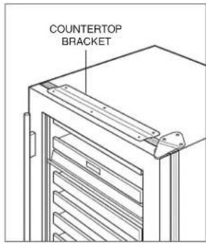
Anchoring.
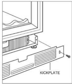
Kickplate installation.
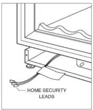
Home security connection.
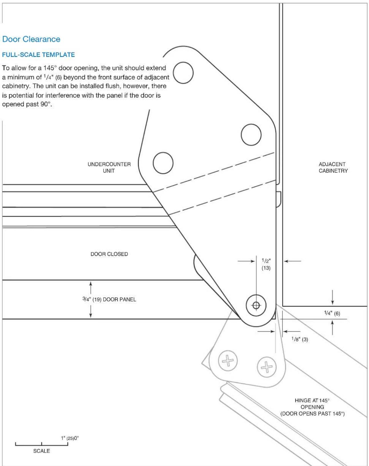
145^ door opening (top view).
Opening Dimensions
STANDARD INSTALLATION
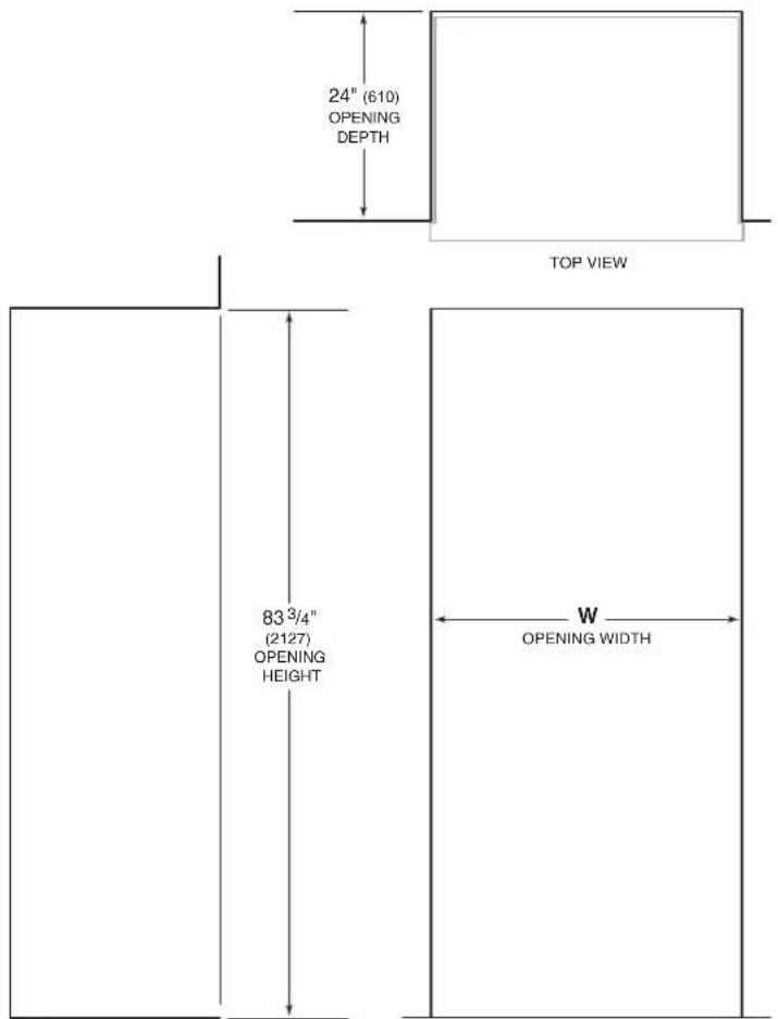
SIDE VIEW
FRONT VIEW
NOTE: Shaded line represents profile of unit.
OPENINGWIDTHW
BW-30 29
1/2" (749)
If two units are installed side by side, refer to page 12.
Opening Dimensions
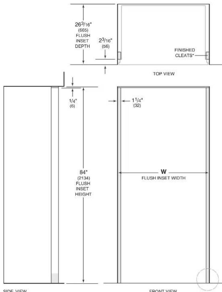
FLUSH INSERT INSTALLATION
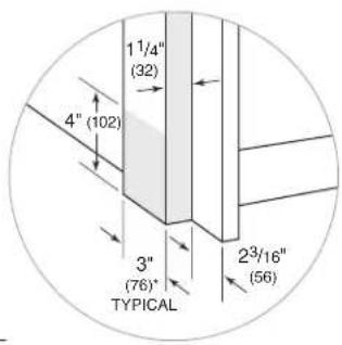
^33^n (78) typical depth. Shaded areas will be visible and should be finished to match cabinetry. NOTE: Shaded line represents profile of unit with ^3 / 4^n (19) panel.
FLUSH INSERT WIDTH W
BW-30 32"
(813)
Dimensions assume a 3/4'' (19) panel thickness. If two units are installed side by side, refer to page 13.
Opening Dimensions
DUAL STANDARD INSTALLATION
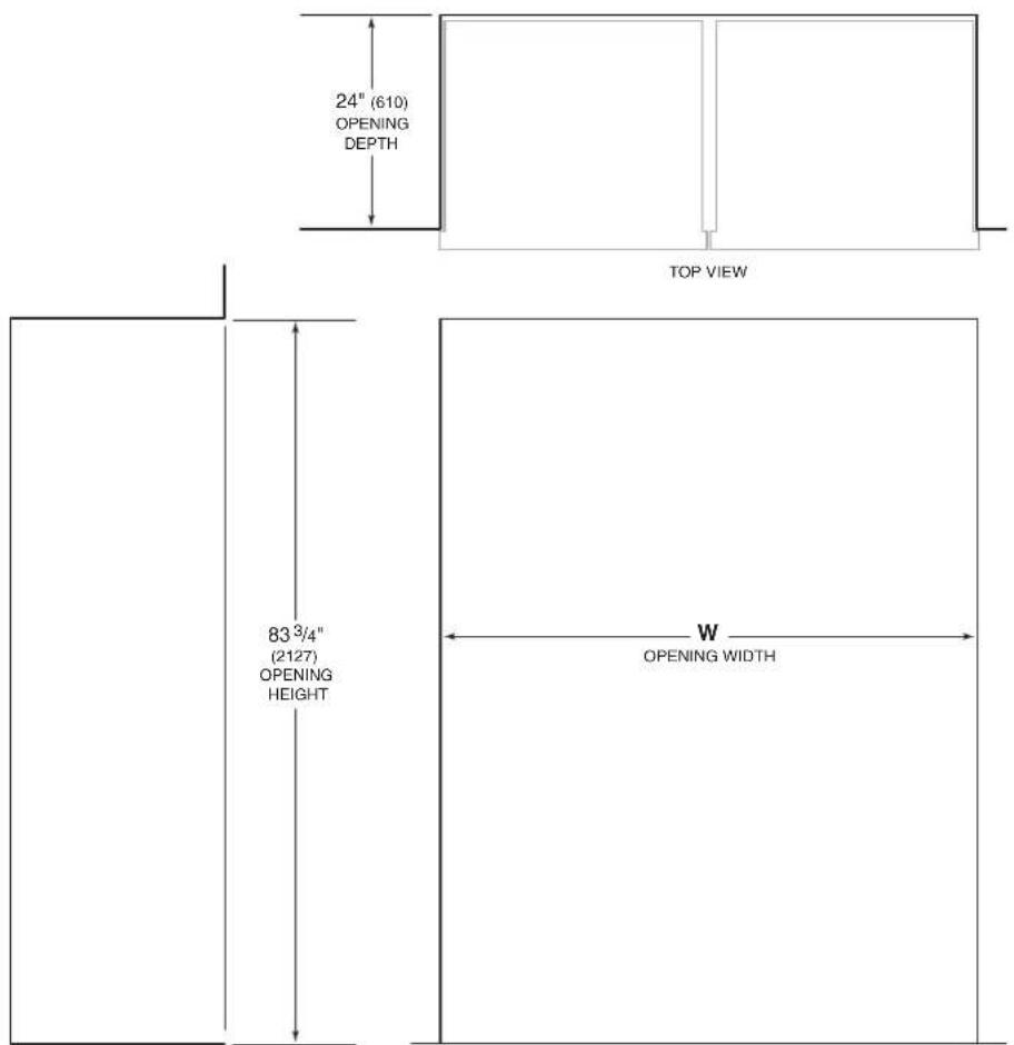
SIDE VIEW
FRONTVIEW
NOTE: Shaded line represents profile of unit.
| DUAL OPENING WIDTH W | |
| BW-30 and 30" Built-In Model 59 | 3/4" (1518) |
| BW-30 and 36" Built-In Model 65 | 3/4" (1670) |
A dual installation kit will be required for this installation.
Opening Dimensions
DUAL FLUSH INSERT INSTALLATION
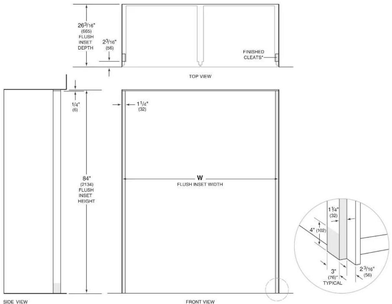
^ 3'' (76) typical depth. Shaded areas will be visible and should be finished to match cabinetry.
NOTE: Shaded line represents profile of unit with ^3/^ ^ (19) panel.
DUAL FLUSH INSETWIDTH W
| BW-30 and 30" Built-In Model 62 | 1/4" (1581) |
| BW-30 and 36" Built-In Model 68 | 1/4" (1734) |
Dimensions assume a 3/4'' (19) panel thickness. A dual installation kit will be required for this installation.
Dual Installation
If two units are installed side by side, a dual installation kit may be required. Installations without a custom filler strip require a dual installation kit. If a dual installation kit is not specified, a 2" (51) filler strip is recommended between units. Dual installations without a filler strip can only be accomplished using two units with opposite hinges. Refer to the illustrations below.
Dual installation kits are available through an authorized Sub-Zero dealer. For local dealer information, visit the find a showroom section of our website, subzero.com. For questions regarding the installation, call Sub-Zero customer care at 800-222-7820.
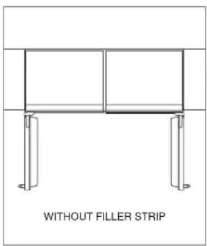
Opposite hinges.
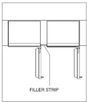
Same side hinges.
Electrical
Installation must comply with all applicable electrical codes.
The electrical supply should be located within the shaded area shown in the illustration below. A separate circuit, servicing only this appliance is required. A ground fault circuit interrupter (GFCI) is not recommended and may cause interruption of operation.
ELECTRICAL REQUIREMENTS
Electrical Supply 115 VAC, 60 Hz
Service 15 amp
Receptacle 3-prong grounding-type
CAUTION
The outlet must be checked by a qualified electrician to be sure that it is wired with the correct polarity. Verify that the outlet is properly grounded.
WARNING
Do not use an extension cord, two-prong adapter or remove the power cord ground prong.
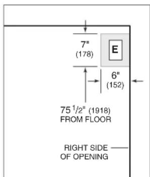
Electrical supply location.
Preparation
Uncrate the unit and inspect for damage. Remove the wood base and discard shipping bolts and brackets. Remove and recycle packing materials. Do not discard the kickplate, anti-tip brackets and hardware.
Completely retract the front leveling legs to allow the unit to be moved into position. The front and rear leveling legs can be adjusted from the front once the unit is in position.
Remove the drain pan to avoid damage, and allow for proper appliance dolly placement.
The grille assembly should be removed prior to moving the unit. To remove, pull out on the bottom edge of the grille and rotate upward. Loosen the two back grille mounting screws and remove the two front grille mounting screws. With the grille held firmly, pull forward to remove. Refer to the illustrations below.
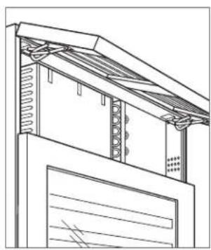
Grille removal.
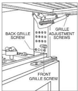
Grille mounting screws.
Anti-Tip Bracket
WARNING
To prevent the unit from tipping forward, the anti-tip brackets must be installed.
The two anti-tip brackets must be installed exactly 24^ (610) from the front of the opening to the back of the brackets and a minimum of 4^ (102) from the sides of the opening. This depth will increase to 26^3 / 16^ (665) for a flush inset installation, based on 3 / 4^ (19) thick panels. Failure to properly position the anti-tip brackets will prevent proper engagement.
Use all anti-tip bracket hardware as instructed for wood or concrete floors.
IMPORTANT NOTE: For wood or concrete floor applications, if the #12 screws do not hit a wall stud or wall plate, use the #8 screws and #12 washers with the wall anchors.
IMPORTANT NOTE: In some installations the subflooring or finished floor may necessitate angling the screws used to fasten the anti-tip brackets to the back wall.
ANTI-TIP HARDWARE
2 Anti-tip brackets
12#12x2 1/panhead screws
4 38'' - 16 × 3^34 wedge anchors
12 #12 flat washers
4#8-18x1 1/4" truss head screws
4 Nylon Zip-it wall anchors
WOOD FLOOR
After properly locating the anti-tip brackets in the opening, drill pilot holes 3/16'' (5) diameter maximum in the wall studs or wall plate. Use the #12 screws and washers to secure the brackets. Verify the screws penetrate through the flooring material and into wall studs or wall plate a minimum of 3/4'' (19). Refer to the illustration below.
CONCRETE FLOOR
After properly locating the anti-tip brackets in the opening, drill pilot holes 3 / 16'' (5) diameter maximum in the wall studs or wall plate. Drill 3 / 8'' (10) diameter holes into the concrete a minimum of 1^1 / 2'' (38) deep. Use the #12 screws and washers to secure the brackets to the wall, and use the 3 / 8'' wedge anchors to secure the brackets to the floor. Verify the screws penetrate wall studs or wall plate a minimum of 3 / 4'' (19). Refer to the illustration below.
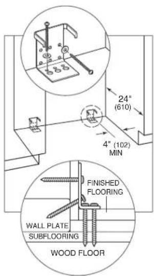
Wood floor.
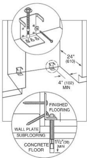
Concrete floor.
Anti-Tip Bracket
CONCRETE WEDGE ANCHOR INSTALLATION
1Drilla 3 / 8'' (10) diameter hole any depth exceeding the minimum embedment. Clean the hole or drill additional depth to accommodate drill fines.
2 Assemble the washer and nut flush with the end of anchor to protect threads. Drive the anchor through the material to be fastened until the washer is flush with the surface material.
3 Expand the anchor by tightening the nut 3-5 turns past hand-tight position or to 25 ft-lb of torque.
WARNING
Verify there are no electrical wires or plumbing in the area which the screws could penetrate.
CAUTION
Always wear safety glasses and use other necessary protective devices or apparel when installing or working with anchors.
Anchors are not recommended for use in lightweight masonry material such as block or brick, or for use in new concrete which has not had sufficient time to cure. The use of core drills is not recommended to drill holes for the anchors.
Custom Panels
For overlay and flush inset applications, custom door and grille panels must be installed. Panel size is critical for a proper fit. To verify panel requirements and dimensions, refer to the Sub-Zero design guide at subzero.com/specs.
IMPORTANT NOTE: Flush inset applications require a minimum 1/2 (13) reveal on all sides.
Finish all sides of the custom panel. They may be visible when the door is open or through the glass door.
CAUTION
A solid panel cannot be installed over the glass door.
Panel Installation
DOOR PANEL
To install the custom door panel, remove the handle side trim molding. Insert a screwdriver tip into the top corner slot on the handle side and pop out the trim. Remove the screws and frame. Refer to the illustration below.
The door has a 1/4'' (6) frame for the custom panel to slide into. If the panel is thicker than a 1/4'' (6), rout an edge around the panel or mount the panel on a sheet of 1/4'' (6) thick material, then insert into the frame.
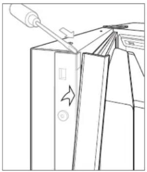
Door side trim.
A. 10'' (3) space is required between the backer panel and the custom panel to allow the panel to slide into the door frame. Refer to the illustrations below for critical dimensions.
Install handle hardware before inserting the panel. Large D-style handles are recommend rather than knobs. Screw heads must be countersunk into the panel.
Slide the panel into the frame.
To reinstall the door trim molding, insert the top of the trim into grooves at the top of the door and work downward, snapping the trim into clips on the door frame.
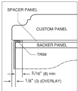
Panel assembly cross section (overlay).
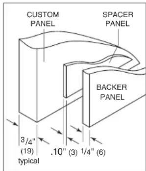
Panel assembly rear view.
Panel Installation
GRILLE PANEL
Remove the bottom grille frame by extracting the lower two corner screws from each side of the grille assembly. Refer to the illustration below.
With the bottom section removed, slide the custom grille panel into the frame. If the panel is thinner than 1/4'' (6), a filler material will need to be installed to achieve a proper fit. Once the panel is installed, reattach the bottom grille frame by sliding the corner brackets back into position, then reinstall the four corner screws.
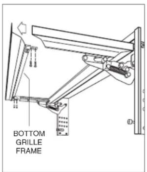
Grille frame assembly.
SIDE PANEL
When installing a custom side panel, an accessory kit is required and is available through an authorized Sub-Zero dealer. For local dealer information, visit the find a showroom section of our website, subzero.com. Stainless steel and white enamel side panels are also available from an authorized Sub-Zero dealer.
IMPORTANT NOTE: The use of side panels may change the width of the opening.
A custom side panel must be a minimum of 24^ (610) deep and 1 / 2^ (13) thick. Routing will be necessary for the side panel to fit flush against the side of the unit. Refer to the illustrations below.
IMPORTANT NOTE: The height of the side panel will vary with the height of the grille. Verify the finished height before modifying panels.
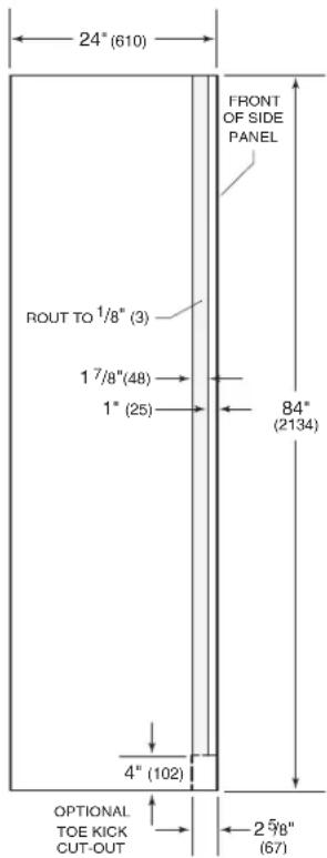
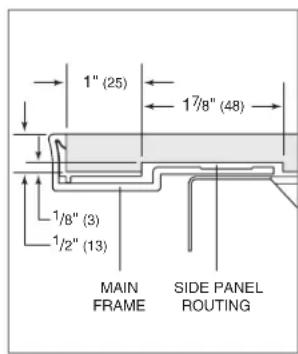
Routing detail.
Side panel dimensions.
Placement
CAUTION
Before moving the unit into position, secure the door closed and protect any finished flooring.
Use an appliance dolly to move the unit near the opening.
If the unit has been on its back or side, it must stand upright for a minimum of 24 hours before connecting power.
If the unit will be connected to a home security system, run lead wires through the compressor compartment prior to positioning the unit. Refer to page 22. Once the unit is in position, wiring connection can be completed from the front.
Plug the power cord into the grounded outlet, then roll the unit into position. Verify the anti-tip brackets are properly engaged.
IMPORTANT NOTE: If used, side panels will need to be installed before the unit is placed in its final position. Refer to page 19.
Alignment
LEVELING
Once the unit is in position, turn the front leveling legs clockwise to adjust the height. The rear height adjustment can be made from the front of the roller base. Using a 3/8'' socket, turn the 3/8'' hex bolt clockwise to raise the unit or counterclockwise to lower. Use the lowest torque setting when using a power drill. Do not turn the rear leveling legs by hand. Refer to the illustration below.
When the unit is properly leveled, door adjustments are less likely to be necessary.
IMPORTANT NOTE: Level the unit to the floor, not surrounding cabinetry. This could affect the operation of the unit, such as door closing.
WARNING
To reduce the possibility of the unit tipping forward, the front leveling legs must be in contact with the floor.
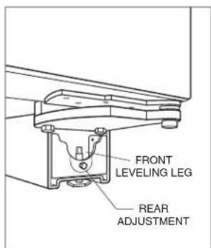
Leveling.
Alignment
DOOR ADJUSTMENT
The door can be adjusted in and out, side to side tilt and up and down.
To make adjustments, slightly loosening the two upper hinge bolts on the upper hinge plate using a 1/2'' wrench. Refer to the illustration below.
In and out adjustment | For a left-hinge door, using a 5/32 allen wrench, turn the adjustment bolt clockwise to bring the handle side of the door inward, and counterclockwise to move the handle side outward. Reverse directions for a right-hinge door.
Side to side tilt adjustment | For a left-hinge door, using a 3/8 wrench, turn the adjustment bolt clockwise to raise the handle side of the door, and counterclockwise to lower the handle side. Reverse directions for a right-hinge door.
Up and down adjustment | For a left-hinge door, using a 1/4'' allen wrench, turn the adjustment bolt clockwise to raise the door and counterclockwise to lower. Refer to the illustration below. Reverse directions for a right-hinge door.

Door adjustment bolts.
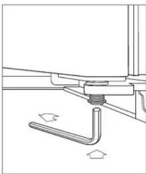
Up and down door adjustment.
Completion
GRILLE INSTALLATION
Install the grille assembly and check for proper fit. The grille is designed to rest on the upper door hinge to minimize the reveal between the top of the door and bottom of the grille. To eliminate interference, the grille height can be adjusted. Loosen the four grille adjustment screws (two on each side) and adjust the grille height as needed. Refer to the illustration below.
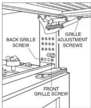
Grille height adjustment.
Completion
HOME SECURITY CONNECTION
If the unit will be connected to a home security system, make connections to the leads shown in the illustration below. Refer to the following color codes:
- Normally open contacts—white with red stripe wire.
- Normally closed contacts—white with blue stripe wire.
Common—gray with white stripe wire.
Use the spade terminals or wire nuts provided to make proper wiring connections.
CAUTION
The alarm circuit in the unit is intended as a low-voltage, low-current device only. It should not be used to switch line power. Any unused terminals should be completely insulated and all wires should be secured away from conductive or moving components.
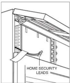
Home security connection.
ANCHORING
After the unit has been leveled and door adjustment completed, anchor the unit to the opening to ensure a proper fit and secure installation.
To anchor the top of the unit, open the grille and install the screws provided, through the grille frame into cabinetry. There are several hole locations. Refer to the illustration below. Check for proper door clearance by opening the door.
To anchor the bottom of the unit, drive a screw through the side hole inside each roller base assembly. The screw will need to go in at an angle to attach properly. Refer to the illustration below. Additional material may be needed behind the cleat to ensure sufficient anchoring.
CAUTION
If the screws provided are not suitable for the installation, use adequate screws.
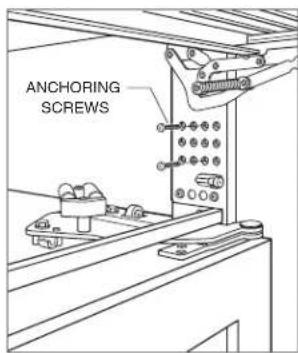
Top anchoring.
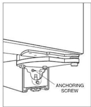
Bottom anchoring.
Completion
KICKPLATE INSTALLATION
Reinstall the drain pan and verify it is in the proper position.
Install the kickplate using screws to attach it to brackets on the inside of each roller base. Refer to the illustration below.
The kickplate must be removable for service. The floor cannot interfere with removal. Refer to the label mounted on the kickplate support for height clearance.
Turn power on by touching POWER on the control panel.
90^ DOOR STOP
The door opens to 110^ . A 90^ door stop is provided with the unit (located behind the grille). Additional 90^ door stop kits are available through an authorized Sub-Zero dealer.
WARNING
Follow all city and state laws when storing, recycling or discarding unused refrigerators and freezers.
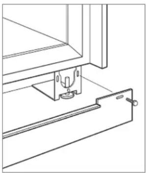
Kickplate installation.
Sub-Zero, Sub-Zero & Design, Dual Refrigeration, The Living Kitchen, Great American Kitchens The Fine Art of Kitchen Design, and Ingredients are registered trademarks and service marks of Sub-Zero, Inc. Wolf, Wolf & Design, Wolf Gourmet, W & Design and the color red as applied to knobs are registered trademarks and service marks of Wolf Appliance, Inc. All other trademarks or registered trademarks are property of their respective owners in the United States and other countries.