
FDS 4.350 - Receiver FOCAL - Free user manual and instructions
Find the device manual for free FDS 4.350 FOCAL in PDF.
| Product type | 4-channel Class D audio amplifier |
| Brand | Focal |
| Model | FDS 4.350 |
| Category | Receiver |
| Dimensions (L x W x H) | 199 x 108 x 43 mm |
| Weight | 850 g |
| Power supply | 12 V (car battery) |
| Idle current | 0.7 A |
| Main fuse | 1 x 30 A (within 40 cm of battery) |
| CEA power (4 ohms) | 4 x 58 W RMS |
| Max power (2 ohms) | 4 x 100 W RMS |
| Max power (bridged 4 ohms) | 2 x 200 W RMS |
| Frequency response | 10 Hz - 50 kHz |
| Total harmonic distortion | 0.05 % |
| Crosstalk (1 kHz) | >65 dB |
| Signal-to-noise ratio (1W/A) | >84 dBA |
| Filters | High-pass (HPF), low-pass (LPF), full range; adjustable from 40 Hz to 400 Hz |
| Input mode selector | 3/4, 1/2, 1+2 (mono summation for subwoofer) |
| Bass boost | Not available |
| Phase adjustment | Not available |
| Built-in protections | Short circuit, low impedance, reverse polarity, DC, undervoltage, thermal protection |
| Minimum speaker impedance | 2 Ω in stereo mode, 4 Ω in bridged mode |
| Warranty | 2 years |
| Installation | Professional installation recommended; 12 V use only |
Frequently Asked Questions - FDS 4.350 FOCAL
User questions about FDS 4.350 FOCAL
0 question about this device. Answer the ones you know or ask your own.
Ask a new question about this device
Download the instructions for your Receiver in PDF format for free! Find your manual FDS 4.350 - FOCAL and take your electronic device back in hand. On this page are published all the documents necessary for the use of your device. FDS 4.350 by FOCAL.
USER MANUAL FDS 4.350 FOCAL
AMPLIFICATEURS FDS
Please validate your Focal-JMlab warranty, it is now possible to register your product online: www.focal.com/warranty

Thank you for choosing Focal and sharing our passion for sound and for music, expressed with precision and purity: "Listen Beyond". These high-tech speaker drivers incorporate enhanced Focal features in speaker driver design to achieve a powerful, high-quality sound. To get the very best out of your system and to exploit the full performance of its speaker drivers, we recommend that you read this booklet, then store it in a safe place to refer to in the future. Any problems caused by failure to follow the instructions may invalidate your guarantee. For optimum results, we recommend that you have the system installed by a professional.

WARNING
This symbol indicates important instructions. Failure to comply with these instructions may result in injury or material damage.
Contents
- 1 FDS amplifier 4.350 or FDS 2.350 or FDS 1.350
- 1 user manual
- 1 set of accessories

WARNING
- Do not operate any functions which may distract you while driving. Functions requiring sustained attention must only be used when the vehicle is at a complete standstill. Always make sure to stop your vehicle in a safe place before operating these functions. Failure to do so may cause an accident.
- Keep the volume at a low level to be able to hear exterior noises while driving the vehicle. Failure to do so may cause an accident.
- Do not open your FDS amplifier or make any modifications to the product. Failure to do so may cause an accident, a fire or an electric shock.
- Only use your FDS amplifier with 12V mobile applications. Any use other than the intended use may cause a fire, an electric shock or injury.
- Use fuses with the adequate amperage. Failure to do so may cause a fire or an electric shock.
- Do not obstruct the heat sink on your FDS amplifier. Internal overheating may occur and cause a fire.
- Wire the connections correctly. Make sure you use the appropriate wire gauge and type of cable. Failure to do so may cause a fire, injury and/or material damage.
- Do not use nuts or bolts on steering or breaking systems, tanks, seat-belt anchor points or other safety elements for connecting the ground. Using of these parts as ground may deactivate the vehicle's control system and cause a fire or other damage.
- Keep small parts which could be swallowed, such as bolts, accessories or screws out of the reach of children. Swallowing such parts may cause to serious injury. If swallowed, consult a physician.
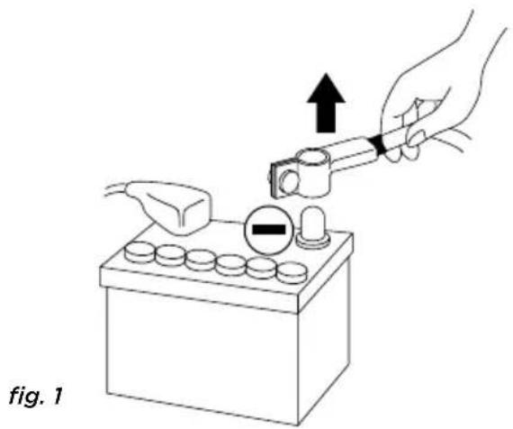
- Before beginning installation, disconnect the negative terminal of the battery to avoid any risk of injury, fire or material damage. (fig. 1)

CAUTION
Prolonged listening at high volumes, over 110dB, can cause long-term damage to your hearing. Listening at volumes over 130dB, even for short periods of time, can cause permanent damage to your hearing.
Stop operation in the event of a problem. Failure to comply with this precaution may cause injury or material damage. If a malfunction persists, return the equipment to your Focal dealer for repair.
Use the specified accessories and be sure to install them correctly. Only use the accessories specified in the user manual and those which are supplied in the packaging. The use of other components could cause internal damage to the equipment, and its installation may not be carried out correctly. The parts used may become loose and cause damage or a technical malfunction of the equipment. Failure to do so may cause an accident, a fire or an electric shock.
Do not install in very humid or dusty places. Avoid installing the equipment in places with high levels of humidity or with an excessive presence of dust. Humidity or dust getting inside the equipment may cause a technical malfunction.
Installing your FDS amplifier
Installation of this product requires technical knowledge and experience. If you are uncertain of your ability to correctly install the amplifier, we strongly recommend you contact your Focal dealer who will install it for you, so that you will be able to take full advantage of the full capabilities of your FDS amplifier.
Wiring your FDS amplifier
Only use the cables recommended in this manual and the accessories supplied. The speaker cable must ONLY be used for connecting the amplifier to the speaker drivers. The wire gauge of power cables must correspond with those indicated in the table (paragraph 3.1) and is according to the power of your amplifier and the length of cable required. Use double or triple shielded RCA cables to avoid any interference of the low-level signal.
Operating time of your FDS amplifier
Avoid using the amplifier for extended periods of time without starting the vehicle. This may cause the battery to become flat prematurely.
Cooling system
Do not cover the top of your FDS amplifier as this may cause overheating.
Materials required for installation (in addition to accessories supplied):
- 2 sheaths of an adequate cross section (1 sheath for the power cable, 1 sheath for the speaker cables, REMOTE cable and RCA low-level wires)
- Multimetre (voltage/amperage)
- Soldering iron + tin solder
- Crimpers
- Wire stripper
- Wire cutter
- Spanner for battery terminal
- Hand drill and matching drill bits
- Heat-shrink tubing of adequate diameter for the different cables
- Power cable of adequate length and wire gauge
- Remote turn-on cable (REM input on amplifier) of adequate length and wire gauge
- Grounded terminal cable of adequate length and wire gauge
- Fuse holder and adequate fuse
- Spade terminal for connecting to positive (+) battery terminal
- Spade terminal for connecting to the chassis of the vehicle (-)
- Screw with a minimum 6mm screw head and its nut for grounding to the chassis of the vehicle
Installation:
The following section deals with issues related to the vehicle which must be considered for the installation of your amplifier. You will save time by planning the layout of the system and wiring in advance.
Please ensure during this preparatory phase, that all the settings remain accessible once the installation is complete.
Before beginning the installation, please follow these rules carefully:
1 - After thoroughly reading the user manual, make sure you have understood all the instructions before installing the amplifier.
2 - Disconnect the negative terminal of the battery before beginning the installation. (fig.1)
3 - To facilitate the assembly, we strongly recommend you unwind all the wires before installing the amplifier.
4 - Route all RCA, speaker and REM cables, away from the power cables in order to avoid any signal interference.
5 - Use quality connectors and Y-type spade terminals on the amplifier terminal board to ensure a reliable installation and to minimise any loss of signal or power.
6 - Before carrying out any operation, be extremely careful not to cut or drill through the fuel tank, fuel, brake, hydraulic or vacuum lines, any electrical wiring or safety device.
7 - Never route a wire under the vehicle. Wiring must be installed inside the vehicle. When routing the cables, make sure they do not impede your driving. Cables obstructing or protruding out from areas such as the steering column or pedals (brake, accelerator, clutch, etc...) can be extremely dangerous.
8 - Avoid routing wires over or through sharp edges. Any wire routed through metal must be protected with a cable grommet. Route the cables well away from mobile parts (seat rails...) and sharp or pointed edges. This will avoid damaging the wires and getting them caught which may cause a short circuit.
9 - Always protect the battery and electric circuit from potential damage with fuses. Install a fuse holder and adequate fuses on the 12V positive (+) power cable less than 40cm away from the battery terminal. Ideally, this above-mentioned distance should be as short as possible (fig.5).
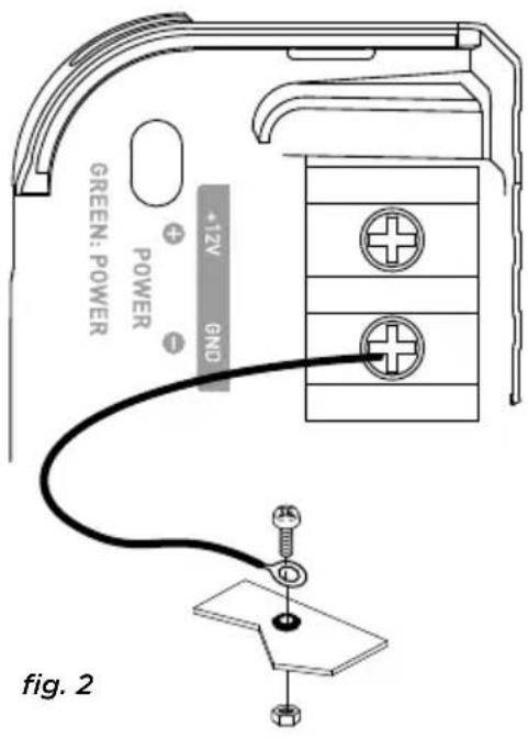
10 - Prepare the chassis ground by scraping off any trace of paint on the metal surface in order to ensure proper grounding. The grounding connections should also be as short as possible and ALWAYS connected to metal welded to the body or the chassis of the vehicle (fig. 2). The ground point which is generally chosen is the one connecting the negative terminal of the battery to the chassis of the vehicle.
11 - NEVER install this equipment in the engine compartment of the vehicle. This will void the warranty.
1 - Positioning of your FDS amplifier
Where to install your FDS amplifier?
Due to the power of the amplifier, heat dissipation is required for correct operation. For this reason, the amplifier must be installed in a well-ventilated area, particularly the top of the amplifier. Avoid covering or embedding the amplifier in its installed location.
2 - Mounting your FDS amplifier
Position your amplifier at the desired location and make matchmarks.
Locate the attachment points in your surface by removing the caps at each end.
Use the fixing screws supplied (adapted for wooden surfaces).
3 - Wiring your FDS amplifier

WARNING
If you are uncertain of your ability to correctly install the amplifier and to wire the system properly, get a Focal dealer/installer to do it for you.

CAUTION
Avoid routing power cables close to low-level input cables (LOW LEVEL INPUTS), close to the car aerial or sensitive equipment and harnesses. High-current power cables can cause interference that affects audio signal.

CAUTION
Keep the cables as short as possible to maximise the quality of the installation. This will also limit signal loss.

CAUTION
Before beginning the connection phase, remove the negative (-) terminal of the battery of the vehicle. (fig.1)
3.1 - What wire gauge should I use for the power cable?
Your FDS amplifier requires a power supply of adequate amperage.
The required wire gauge of power cables depends on the length of wiring to the battery. See recommended wire gauge in the table below:
| Length of cable to the battery in metres | |||||
| Length < 3 | m < 4 m < 5 m < | 6 m < 7 m | |||
| Cross sectional area in mm2 | >4 mm2 | >5 mm2 | >5 mm2 | >5 mm2 | >5 mm2 |
| AWG < 11 A | WG < 10 AWG < | 10 AWG < 10 AW | G < 10 AWG | ||
Compliance with these wiring rules is essential for the safety of your electrical Installation and important for maintaining maximum performance of your FDS amplifier.
3.2 - Wiring the input and output signals on your FDS amplifier
Route the RCA low-level wires, the speaker cables and the REM cable ensuring to insulate them from other powerful automobile accessories, particularly electric motors (windshield wiper...). Keep the whole length of the cables, which will be adjusted later on.
3.3 - Wiring the power supply to your FDS amplifier
3.3.1 - Route the positive power cable (+) making sure when doing so to route the cable to the opposite side of the cables that you have previously installed – this is to avoid any interference. DO NOT CONNECT THE CABLE YET.
FDS AMPLIFIERS
User manual
3.3.2 - Get hold of the negative power cable (-). This cable should be as short as possible and ideally should not be any longer than 1 metre, to ensure a perfect connection between the amplifier and the chassis of the vehicle. The cable and wire gauge must comply with the table in section 3.1. Find a suitable grounding point, then sand it to remove any traces of paint or other coating to maximising the quality of the contact point. Drill a hole in the metal that you have previously sanded, making a hole the same diameter as the screw you are using, making sure that there are no fuel lines, cables or any other sensitive vehicle devices nearby. Crimp the black Y-type spade terminal supplied to the end of the cable. Screw the black Y-type spade terminal firmly to the GND terminal on your FDS amplifier (fig. 2). Tin the other end of the cable and then crimp or solder it onto the intended spade terminal. Insert the screw through the spade terminal, then put the screw and the nut in place and screw tight. (fig. 2)
3.4 - Connecting the input signals to your FDS amplifier
You can now start the connection phase of the input/output cables.
3.4.1 - Your head unit is equipped with RCA outputs (fig. 3)
Connect the RCA cables to the amplifier. Be careful to respect the polarities (INPUT Left = black or white, INPUT Right = red). Then connect the other end of the RCA cable(s) to the appropriate RCA* outputs of the head unit (Left and Right).
Now connect the REMOTE cable to the amplifier (REM terminal) and screw tight. Connect the other end of the REMOTE cable to the REMOTE terminal on the head unit. Finally, connect the speaker driver cables to the amplifier. Be careful to respect the polarities (+ with +; - with -) by using the red and black Y-type spade terminals supplied.
FDS AMPLIFIERS
User manual
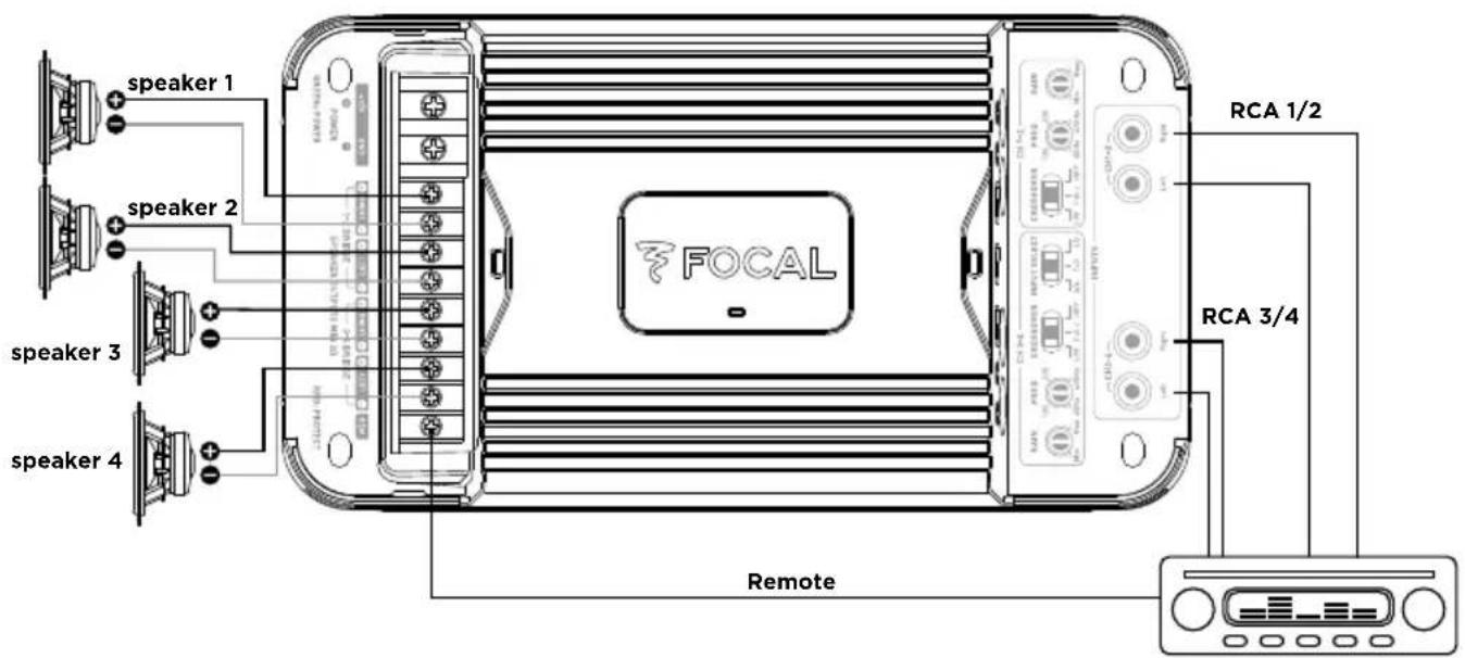
fig. 3.1 - FDS 4.350
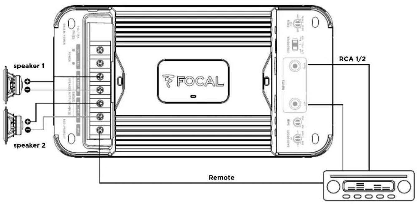
fig. 3.2 - FDS 2.350
Simple voice coil speaker
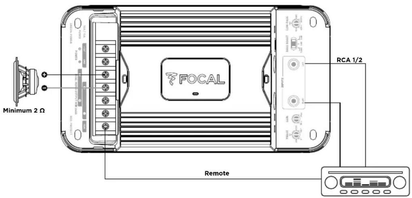
fig. 3.3 - FDS 1.350, simple voice coil wiring
Double voice coil speaker
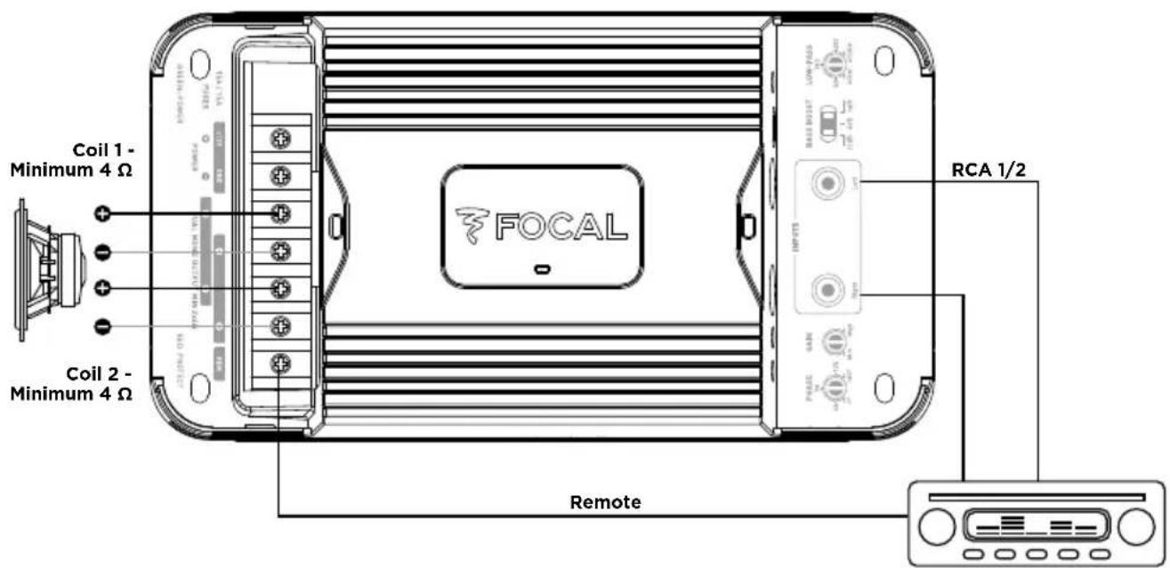
fig. 3.3 bis - FDS 1.350, double voice coil wiring
FDS AMPLIFIERS
User manual
Speaker pair
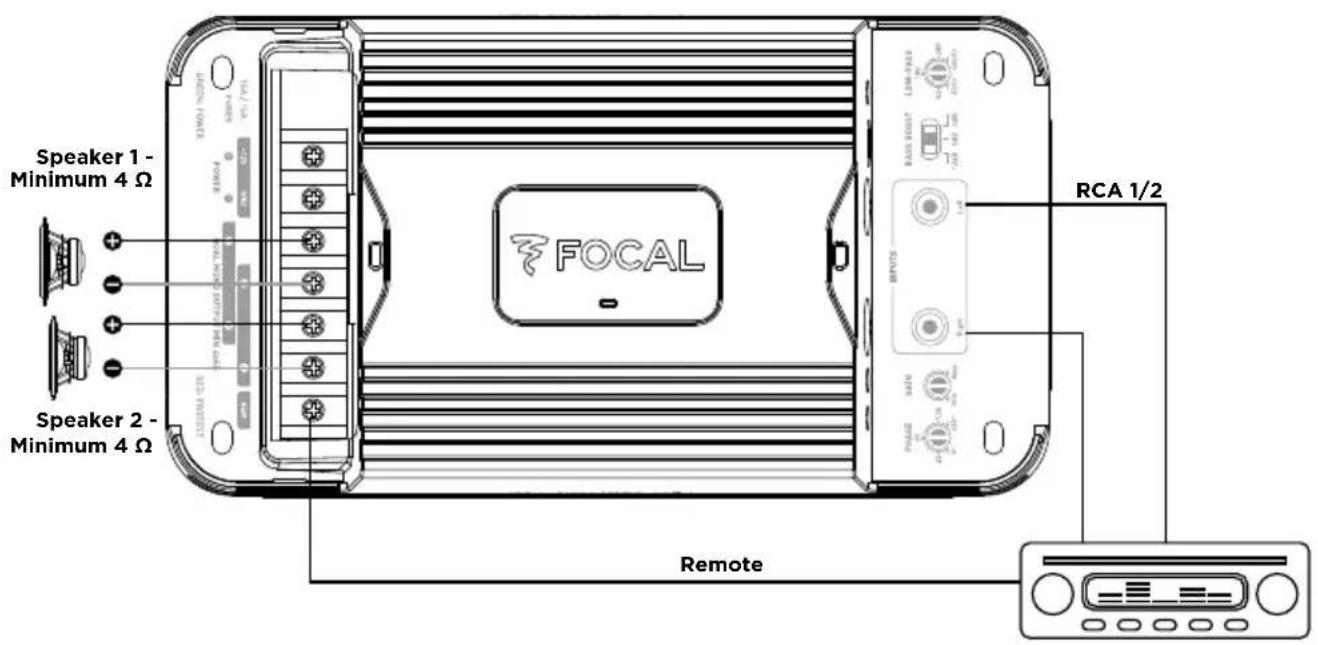
fig. 3.3 ter - FDS 1.350, speaker pair wiring

CAUTION
The speaker drivers or speaker driver kits wired to your FDS amplifier must have a minimum impedance of 2 Ohms.
In bridged mode (FDS4.350 and FDS2.350) or dual output mode (for the FDS1.350), the speaker drivers or speaker driver kits wired to your FDS amplifier must have a minimum impedance of 4 Ohms.
Use of equipment with an inferior impedance will void the warranty.
3.6 - Wiring power supply to your FDS amplifier

CAUTION
The cable connecting the positive (+) terminal of the battery to the “+ BATT” terminal of the amplifier MUST be fused (ampere rating: 30 amperes) less than 40cm away from the battery of the vehicle. The connections on the fuse holder must be fully insulated.
Open the fuse holder, removing the fuse with care. Fix the base of the fuse holder.
Cut a length of power cable between 10 and 40cm (maximum). Strip 1cm, then tin. Screw the cable to the terminal of the fuse holder (battery side). Crimp the power cable to the intended spade terminal and screw to battery terminal.
Strip 1cm from the remaining length of cable, then tin. Screw the cable to the other fuse holder terminal.
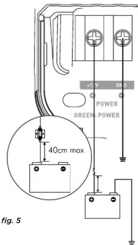
Prepare the positive power cable (+) to connect it to the amplifier by using the adequate Y-type spade terminal, then block the cable by screwing tight. (fig. 5)
FDS AMPLIFIERS
User manual

CAUTION
In addition to this fuse near the battery, the FDS4.350 has an additional fuse which requires installation near the amplifier.
Use the connector supplied with the fuse holder (fig. 6). Crimp the power cable to the intended spade terminal.
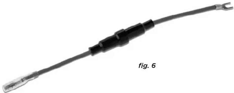
Connect the connector to the amplifier by using the adequate spade terminal, then block the cable by screwing tight.
Insert the fuse into the fuse holder(s), and screw tight.
3.7 - Start-up and checks
The connection phase is now complete. You must now check the power supply (is correct) and that everything is working correctly (head unit/amplifier/speaker). Set the source gain to its minimum. Set the gain on your amplifier to 1/3 of the way. Turn on the different elements. Once all the elements are on, carry out a test at low volume.

CAUTION
FDS4.350 is working with a particular starting sequence. It needs both REM signal and audio signal at the input to start correctly. Please, check audiosignal presence with sufficient volume on the head unit.
4 - Control panel and connections
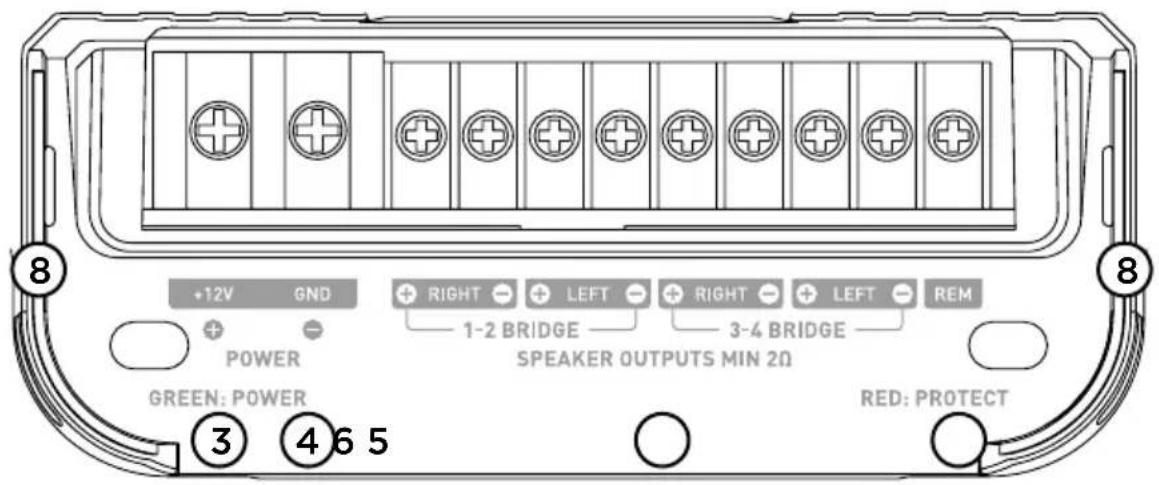
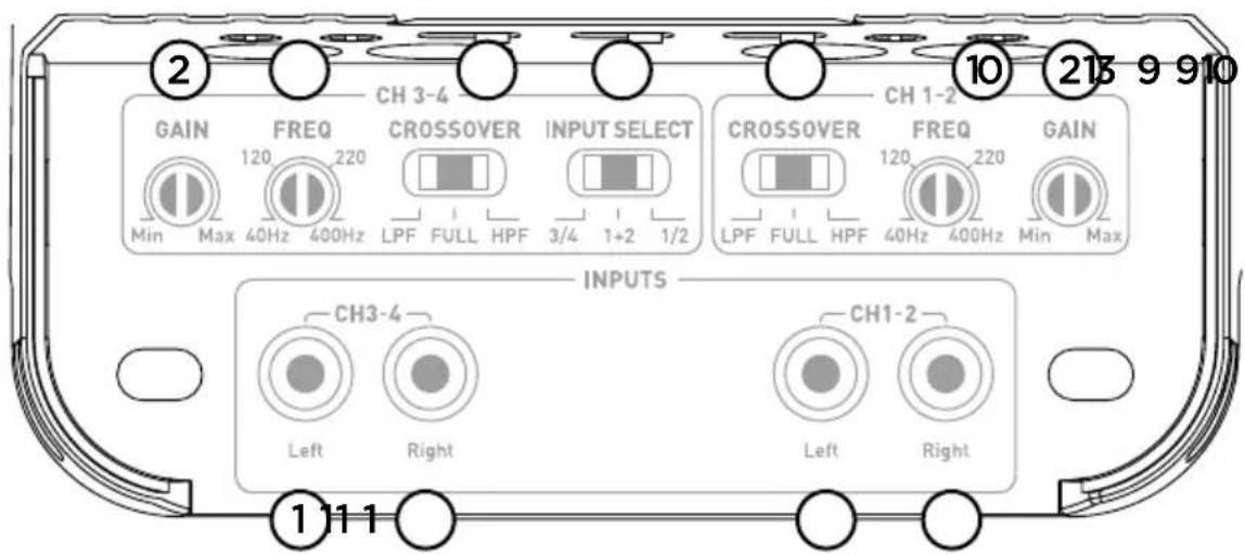
fig. 7.1, FDS 4.350
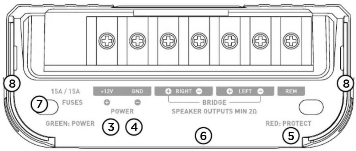
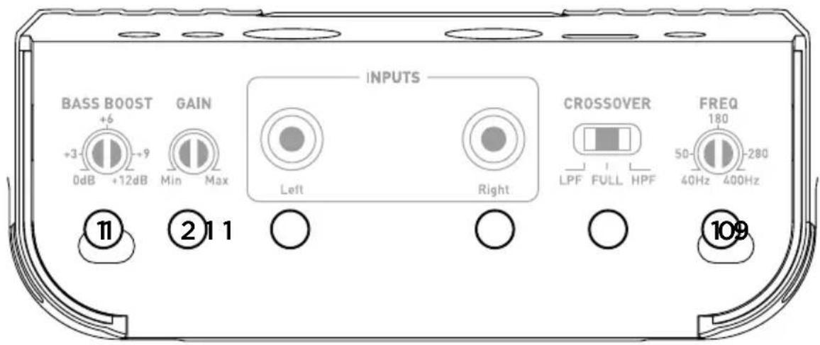
fig. 7.2, FDS 2.350
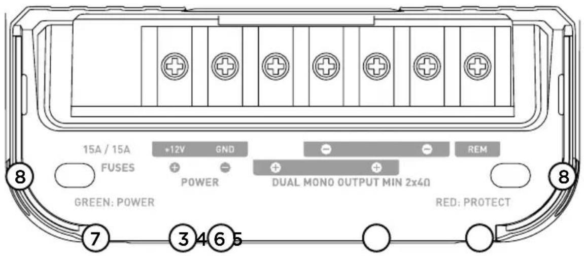
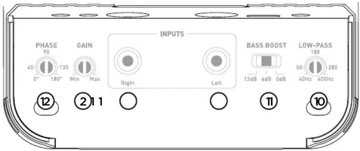
fig. 7.3, FDS 1.350
1°/ INPUT(S): The RCA plugs are dedicated to the low level signal input.
2°/ GAIN: The rotary GAIN control potentiometer allows you to adjust the incoming signal to the amplifier. CAUTION: increasing the input gain does not mean more power, but more noise. The voltage gain varies between 0.2V and 5V. Optimisation of the sound system consists in applying the maximum gain as soon as possible beforehand on the sound system and then the minimum gain afterwards. This potentiometer must be set according to the source volume (line output level). Start by setting the amplifier gain to its lowest level. Gradually turn up the level of the source volume up to the 3/4 of the way. Turn up the amplifier gain level to the desired maximum listening level. Turn down the level if distortion occurs.
3°/ +12V: the power connector“+BATT” is dedicated to receive the power cable connecting the amplifierto the positive (+) terminal of the battery.
4°/ GND: the GND (ground) power connector is dedicated to receive the negative (-) power cable connecting the amplifier to the chassis of the vehicle.
5°/ REM : the REM connector connects the amplifier to the source (head unit via a REM or REMOTE output on the head unit. This enables the automatic turn-on of the amplifier as soon as the source (head unit) is turned on.
6°/ SPEAKERS : the SPEAKERS connectors link the amplifier to the speaker drivers. The polarities MUST be respected (+ amplifier + crossover or + speaker driver / - amplifier - crossover or - speaker driver).
7°/ FUSES: The FUSE connector is dedicated to receive the amplifier fuse(s). In case of replacement, make sure that the ampere rating is correct.
8°/ LEDs: the indicator LEDs enable you to check the amplifier is working correctly. A continuously illuminated green LED means the equipment is working correctly. A continuously illuminated red LED means the equipment is not working correctly. See troubleshooting section page 6.
9°/ Crossover selector: the CROSSOVER switch enables you to choose to activate a high-pass filter (HPF), a low-pass filter (LPF) or full range mode (FULL).
10°/ Setting the crossover cut-off frequency: This rotary potentiometer enables you to adjust the value of the high-pass or low-pass filter. The selected value determines the frequency up to which or from which the signal will be cut off.
11°/ Bass boost : the switch or rotary potentiometer (FDS1.350 or FDS2.350 respectively) enables you to increase the volume of the bass from 0 to 12dB.
12°/ Phase : the PHASE rotary potentiometer enables you to adjust the channel phase setting according to the rest of the installation. Adjusting the phase of the subwoofer enables the speaker driver output to be in phase or out of phase with the other speaker drivers. On a theoretical period of a signal, one of the sources can be adjusted slightly for the phase to be perfectly balanced at the listening point.
13°/ Mode selector: The INPUT SELECT switch (only available on the FDS4.350 model) enables channels 1 and 2 to be played through channels 3 and 4. So, if you only have one output (one right and one left), you can still amplify the four channels by activating the 1/2 mode.
If you want to use the FDS4.350 with its independent 4-channel input configuration, select mode 3/4.
If you want to use the FDS4.350 in 3-channel mode, select mode 1+2. Channels 3/4 will then receive the mono signal from channels 1 and 2 of your subwoofer.
5 - Troubleshooting
The state of the different indicator LEDs refer to the nature or the cause of a malfunction.
Check the possible causes shown below. If, despite these checks, the equipment is still not working correctly, contact your FDS amplifier installer or dealer.
| Status of indicator LEDs | Presence of sound | Possible cause Action | |
| Illuminated red NO | Output short circuit | Turn off the sound system | Check the speaker drivers, their minimum impedance, their connections and the speaker driver cables. |
| Off NO No power or poor | connection | Turn off the sound systemCheck power source is 12VCheck the power cables and their polarity. Check the fuses | |
| Flashing from red to green | Distorted, absent or alternating | Overheating Turn | off the sound systemWait for your amplifier to cool down before resuming use. |
| Off NO No REM signal Turn on the sound system | Check power on the REM terminal. | ||
| Off NO Fuse failure Turn off the sound system | Check and replace the fuses if necessary. | ||
| Off / illuminated green | YES/NOOr distorted | Grounding defect Turn | off the sound systemCheck the continuity of your connection from the GND terminal to the chassis of the vehicle. |

CAUTION
FDS4.350 is working with a particular starting sequence. It needs both REM signal and audio signal at the input to start correctly. Please, check audiosignal presence with sufficient volume on the head unit.
6 - Technical specifications
| MODEL FDS4.350 | 4/3/2-channel D class amplifier | FDS2.350 Stereo D class bridgeable amplifier | FDS1.350 Mono D class amplifier with dual output |
| CEA power (4 Ohms) 4 | x 58 W RMS 2 x 10⁵ W R | MS 1 x 210 W RMS | |
| Power max (2 Ohms) 4 | x 100 W RMS 2 x 170 W | RMS 1 x 350 W RMS | |
| Power max (4 Ohms bridged) | 2 x 200 W RMS 1 x 3 | 60 W RMS - | |
| Bandwidth 10 Hz - 50 | KHz 10 Hz - 50 KHz 10 Hz | - 400 Hz | |
| Total harmonic distortion | 0,05 % 0,07 % 0 | 05 % | |
| Cross-talk (1KHz) >65 dB | >65 dB - | ||
| SNR (1W/A) | >84 dBA >84 dBA | - | |
| High-pass/low-pass filter | adjustable 40 Hz-400 Hz | adjustable 40 Hz-400 Hz | Low-pass 40 Hz-400 Hz |
| Bass boost | - | Linear Bass boost centred at 85Hz (0 to 12dB) | Selective Bass boost centred at 50Hz (0/6dB/12dB) |
| Phase adjustment | - | - | progressive (0-180°) |
| Full range mode | √ | √ | - |
| Standby consumption (A) | 0,7 | 0,9 | 0,7 |
| Fuse ratings | 1 x 30 A | 2 x 15 A 2 x 15 A | |
| Protections | Short circuit / low impedance / reversal of polarityDC / power drop / heat protection | ||
| Dimensions (LxWxH) inch/cm | 73/4 × 41/4 × 11/2 199 x 108 x 43 | 73/4 × 41/4 × 11/2 199 x 108 x 43 | 73/4 × 41/4 × 11/2 199 x 108 x 43 |
| Weight (g/lbs) | 850/1.9 | 850/1.9 | 850/1.9 |
Conditions of warranty
All Focal loudspeakers are covered by warranty drawn up by the official Focal distributor in your country. Your distributor can provide all details concerning the conditions of warranty. Warranty cover extends at least to that granted by the legal warranty in force in the country where the original purchase invoice was issued..
AMPLIFICATEURS FDS
Correct elimination of this product.
This marking indicates that within the EU this product should not be disposed of with other household wastes. To prevent any risk to the environment or human health, please recycle them responsibly to encourage the reuse of material resources. To return your used device, please use the return and collection systems available, or contact the retailer where you purchased the product. They can recycle this product safely.


- AMPLIFICATEURS FDS
- WARNING
- CONTENTS
- CAUTION
- INSTALLING YOUR FDS AMPLIFIER
- WIRING YOUR FDS AMPLIFIER
- OPERATING TIME OF YOUR FDS AMPLIFIER
- COOLING SYSTEM
- MATERIALS REQUIRED FOR INSTALLATION (IN ADDITION TO ACCESSORIES SUPPLIED)
- INSTALLATION
- BEFORE BEGINNING THE INSTALLATION, PLEASE FOLLOW THESE RULES CAREFULLY
- POSITIONING OF YOUR FDS AMPLIFIER
- WHERE TO INSTALL YOUR FDS AMPLIFIER
- MOUNTING YOUR FDS AMPLIFIER
- 3.1 - WHAT WIRE GAUGE SHOULD I USE FOR THE POWER CABLE
- 3.2 - WIRING THE INPUT AND OUTPUT SIGNALS ON YOUR FDS AMPLIFIER
- 3.3 - WIRING THE POWER SUPPLY TO YOUR FDS AMPLIFIER
- FDS AMPLIFIERS
- USER MANUAL
- 3.4 - CONNECTING THE INPUT SIGNALS TO YOUR FDS AMPLIFIER
- 3.4.1 - YOUR HEAD UNIT IS EQUIPPED WITH RCA OUTPUTS (FIG. 3)
- SIMPLE VOICE COIL SPEAKER
- DOUBLE VOICE COIL SPEAKER
- 3.6 - WIRING POWER SUPPLY TO YOUR FDS AMPLIFIER
- 3.7 - START-UP AND CHECKS
- CONTROL PANEL AND CONNECTIONS
- TROUBLESHOOTING
- CONDITIONS OF WARRANTY
- CORRECT ELIMINATION OF THIS PRODUCT
Brand : FOCAL
Model : FDS 4.350
Category : Receiver