TC 31 FA - Cooker ROSIERES - Free user manual and instructions
Find the device manual for free TC 31 FA ROSIERES in PDF.

User questions about TC 31 FA ROSIERES
0 question about this device. Answer the ones you know or ask your own.
Ask a new question about this device
Download the instructions for your Cooker in PDF format for free! Find your manual TC 31 FA - ROSIERES and take your electronic device back in hand. On this page are published all the documents necessary for the use of your device. TC 31 FA by ROSIERES.
USER MANUAL TC 31 FA ROSIERES
INSTALLATION: "LE CHANGEMENT GAZ"
INSTALLATION: "ENCASTREMENT"
text_image
Joint 6 mmINSTALLATION: "ENCASTREMENT"
INSTALLATION: "LE RACCORDEMENT GAZ"
INSTALLATION: "LE RACCORDEMENT ELECTRIQUE"
natural_image
Mechanical assembly diagram showing gears and housing components (no text or labels)REGLAGE DU BRÛLEUR DE TABLE
a) en gaz naturel :
Unpacking the appliance ....21
Recommendations 21
Hob features ......22
- INSTALLATION
Safety instructions....23
Modification of the factory gas setting :
* Fitting of the correct jets ......24
* Adjusting of the air ring ....25
Fitting the hob 26/27
Gas connection 28
Electrical connection 29
After final installation of the hob (if modification of the gas setting):
Adjusting of the lower flame on the gas burners.... 30
• USING THE APPLIANCE
The different gas burners ....31
Igniting and setting the burner 32
The hot plate 33
Cooking with the electrical hot plate 34
General maintenance.... 35-36
• TECHNICAL DATA....37
UNPACKING THE APPLIANCE
Inside the appliance, you will find :
• a plastic bag containing :
- the new jets for the gas modification, if required,
- the fixing brackets with screws required for installing the hob in the worktop, and,
- a spanner to change the jets if the factory gas setting does not correspond to your installation requirements.
RECOMMENDATIONS
TO GET THE BEST FROM YOUR APPLIANCE, PLEASE READ THE FOLLOWING CAREFULLY.
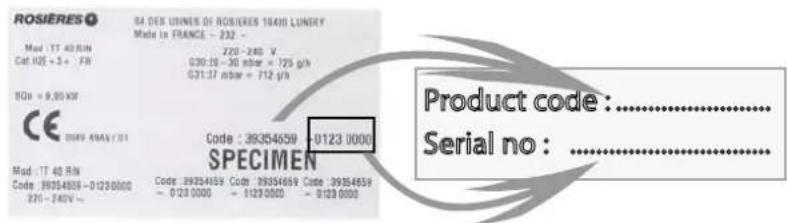
Please keep the operating and installation instructions in a safe place for future reference. Before fixing the hob, note the serial number of the appliance just in case you should require future repairs from our after sales service organisation at some time in the future.
. Rating plate (located under the lower casing of the hob)
text_image
ROSIERES Mod. TT 40 RUN Cat IQE + 3+ - FR SQR = 9,80 KVR CE 2009 4AM/2011 Mod. TT 40 RUN Code: 39354658 - 0123 0000 231 - 240V ~ SA DES UIMNES OF ROSIERES 10400 LUNDAY Made in FRANCE - 232 - 220 - 240 V 030:18 - 30 nbar = 725 g/h G31:17 nbar = 712 g/h Code : 39354659 - 0123 0000 SPECIMEN Product code : ------------------------- Serial no : --------------------------- All accessible parts of the hob will become hot while in operation. Always keep children away from it.
- The hob should be given a quick clean after each use, to avoid the accumulation of spillages and grease. If spillages are not removed, they will harden, and could cause the production of smoke and unpleasant smells.
- When cooking with fats or oils, never leave gas burner unattended. Overheated fats or oils can quickly catch fire.
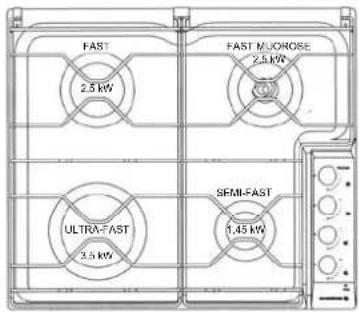
HOB FEATURES
ALL GAS HOB
text_image
FAST 2.5 kW FAST MUOROSE 2.5 kW ULTRA FAST 2.5 kW SEMI FAST 1.45 kWMIXED HOB
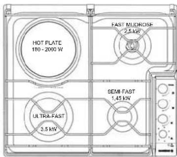
text_image
HOT PLATE 180 - 2000 W FAST MUDROSE 2.5 kW ULTRA FAST 3.5 kW SEMI FAST 1.45 kWTC 31 : Hob 3 gas burners + 1 hot plate 2000 W, and enamelled pan supports.
TC 40 : Hob 4 gas burners, and enamelled pan supports.
TCS 31 : Hob 3 gas burners with safety device + 1hot plate 2000 W, and enamelled pan supports.
TCS 40 : Hob 4 gas burners with safety device, and enamelled pan supports.
TT 31 : Hob 3 gas burners + 1 hot plate 2000 W, and cast-iron pan supports.
TT 40 : Hob 4 gas burners, with cast-iron pan supports.
TR 31 : Hob 3 gas burners + 1 hot plate 2000 W, and enamelled pan supports.
TR 40 : Hob 4 gas burners and enamelled pan supports.
Overall dimensions :
Building-in dimensions - (see chapter "Installation")
Width : 56 cm Depth : 48 cm
INSTALLATION
Installing a domestic appliance can be a complicated operation which if not carried out correctly, can seriously affect consumer safety.
It is for this reason that the task should be undertaken by a professionally qualified person who will carry it out in accordance with the technical regulations in force.
In the event that this advice is ignored and the installation is carried out by an unqualified person, ROSIERES declines all responsibility for any technical failure of the product whether or not it results in damage to goods or injury to individuals.
Before installing the hob :
Omake sure that the appliance is compatible with the gas supply source.
The hob is pre-set in the factory to work with the type of gas shown on the packing and the plate attached to it.
Natural gas G 20-20 mbar / G 25-25 mbar : mains gas
② if necessary, adapt the hob for use with another type of gas: if the hob must be used with another type of gas than the gas pre-set in the factory, it is necessary to adapt the hob gas burners (page 24/25).
The procedure for adaptation consists of :
. fitting the correct jets to ensure nominal delivery,
. adjusting the appearance of the flame by regulating the air ring according to the data given in the table.
For installation :
②built-in hob (page 26/27).
④ make the gas connection according to the type of gas to be used: based on the gas to be used, choose the appropriate gas connection (page 28).
⑤ make the hob electrical connection according to the instructions (page 29).
⑥ adjusting the minimum flame of the taps : if necessary, adjust the minimum flame of the taps by turning the by-pass screw (page 30).
All modification concerning the hob gas setting must be indicated on the rating plate of the hob.
INSTALLATION: "GAS CONNECTION"
- CHANGING THE GAS TYPE: the calorific power output and gas pressure will vary according to the gas supply. Burner setting must be carried out once the gas and electrical installation is complete.
When changing gas type, you must follow the procedure below :
. fit the correct jets,
. adjust the appearance of the flame by regulating the air ring.
. adjust the minimum flame on the taps (see page 30).
• CHANGING THE JETS :
Each jet is designated by size. A special spanner supplied with the appliance is designed to hold the jets securely during the set up operation.
To gain access to the jets :
. remove the pan supports,
. remove the burner cap and body,
. using the spanner supplied with the appliance, unscrew the jet,
. fit the correct jet for the type of gas to be used,
. secure the jet tightly,
. replace the burner body, cap and the pan support.
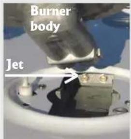
text_image
Burner body JetExample : Ultra-fast 3,5 kW
| Natural gas : G20-20 mbar / G25-25 mbar | Butane gas : G30 28-30 mbarPropane gas : G31 37 mbar | |
4 gas burners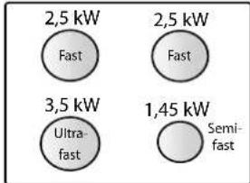 | 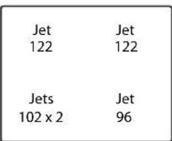 | 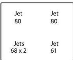 |
3 gas burners + 1 hot plate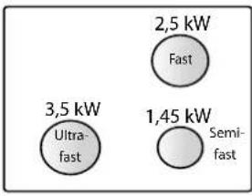 | 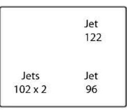 | 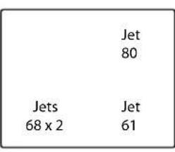 |
INSTALLATION: "GAS CONNECTION"
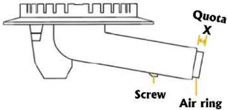
- SETTING THE APPEARANCE OF THE FLAME
- Regulating the air ring on the hob burners: the setting is important as it ensures the correct combustion and enables the burners to work at maximum efficiency. The table refers to the value "X" in mm; it may be necessary to regulate this by plus or minus 1 mm to obtain a perfect flame.
- To gain access to the air rings on the hob burners: remove the pan support, the burner cap and body of the relevant burner. The air ring is located at the lengthening of the burner unit which is fixed by a screw (see drawing).
If necessary : . unscrew the screw that holds the air flow adjuster,
. set the correct distance according to the air adjuster protrudes,
. secure the screw when the operation is completed.
Semi-fast burner 1,45 kW or Fast burner 2,5 kW
text_image
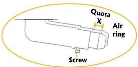
Quota X Screw Air ringUltra-fast burner 3,5 kW
text_image
Quota X Air ring ScrewQuota "X" in mm of the air ring according to the gas setting
| G20-20 mbarG25-25 mbar | G30 28-30 mbar | G31 37 mbar | |
4 gas burners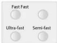 | 10 1014 6 |  | 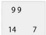 |
3 gas burners + 1 hot plate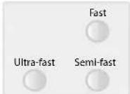 | 1014 6 | 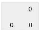 | 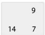 |
INSTALLATION
BUILDING-IN : both the worktop where the hob will be fitted and any adjacent kitchen furniture must be made from heat resistant material and fixed with heat resistant adhesive.
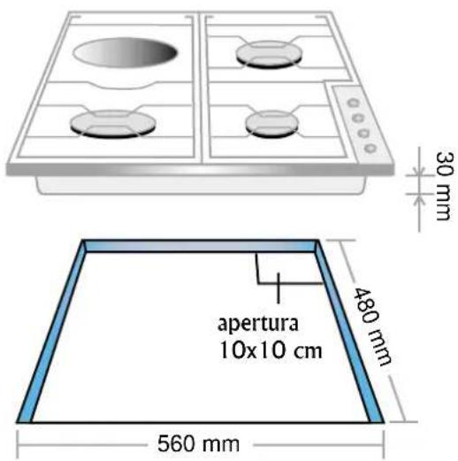
If, when installing the hob, the lower hob face is adjacent to an area normally accessible when handling or cleaning, fit a heatproof partition 1 cm below the base of the hob with a 10X10 cm opening at the rear right-hand corner, to avoid any risk of scorching or damage.
There should also be a 5 cm gap between the appliance and all adjacent vertical surfaces.
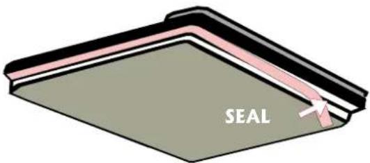
A foam adhesive is supplied with the hob. Stick this seal under the edge of the body as near as possible to the outer edge of the hob. Press round the edges of the hob, so that the seal flattens out and ensures an air tight seal.
Warning : at the rear of the appliance, take care not to block the air inlets necessary for combustion to take place.
FITTING THE SEAL
- Top view of the seal
text_image
SEAL• Cross section of the hob

text_image
seal 6 mmWorktop level
- Take care not to block the air inlets necessary for combustion to take place -
INSTALLATION
The body of the hob is fitted with 4 location holes to take the fixing brackets that secure the the hob in the unit. Place the 4 fixing brackets in such a way that the hob is placed perfectly in the support unit.
Location for fixing brackets
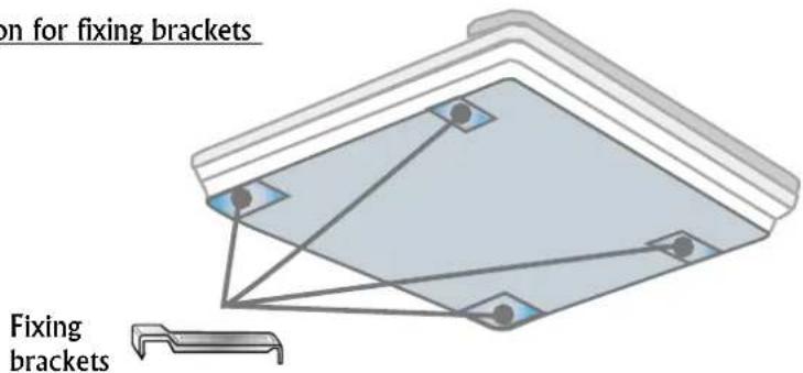
text_image
on for fixing brackets Fixing bracketsBuilding-in according to TYPE X (Norm CEI 335-2-6)
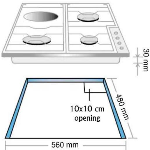
text_image
30 mm 10x10 cm opening 480 mm 560 mmINSTALLATION: "GAS CONNECTION"
The hob can be built-in; it is type "X" for built-in hob (in compliance with electrical regulations EN 60.335.2.6); in class 3 (in compliance with gas regulations EN 30.1.1); adjoining furniture should not be higher than the level of the hob.
This appliance is not connected to an evacuation device for the products of combustion. It must be installed and connected in compliance with the norms in force in the country of installation. Particular attention should be given to the availability of ventilation. The turnover of air necessary for combustion is a minimum of 2 m^3/h per kW of power.
Gas connection should be carried out in compliance with the norms in force in the country of installation. A stop tap, a regulator valve or a release valve for propane gas, should be fitted to the gas supply pipe. Use only taps, regulator valves, connectors and flexible hoses with the official mark of approval of the country of installation.
Built-in appliance
Butane Rigid - Flexible pipe with mechanical connectors (1) - Propane Rigid - Flexible pipe with mechanical connectors (1) - Natural Rigid - Flexible pipe with mechanical connectors (1) -
(1) on condition that the hose is accessible along the whole of its length it should be located so it cannot be reached by naked flame or affected by combustion gases. Neither should it be near hot parts of the hob nor anywhere where hot spillages could affect it.
2 POSSIBLES MEANS OF CONNECTION :
• CONNECTION BY RIGID PIPE
Connect directly to the threaded end of the inlet pipe.
- CONNECTION BY FLEXIBLE PIPE WITH MECHANICAL CONNECTOR
Screw the nuts of the flexible pipe directly on to the inlet pipe at one end and the gas supply stop tap at the other.
We recommend this type of connection.
INSTALLATION: "ELECTRICAL CONNECTION"
The mains electricity supply connected to the appliance should comply with the norms in force in the country of installation.
Connection to the mains electricity supply should be through a socket with an earth terminal, or through an intermediary switching device with a gap between contacts of at least 3 mm. The power supply unit must be protected by appropriate fuses and use cables of a large enough cross section to provide a normal supply to the appliance.
The hob is fitted with a power supply cable* with plug which allow it to be connected only to a power supply of 230 V between phases, or between phase and neutral.
- Connect to a 10/16 Amp socket. Before connecting, it is compulsory to check :
. the power supply voltage shown on the electricity meter,
. the adjustment of the circuit breaker, and
. the fuse rating 10A.
Note: the socket must be reachable for any eventual repair. Take care of its location at the time you install the hob.
Warning : before proceeding with the connection, check the continuity of the earthing of the power supply unit.
We cannot be held responsible for any accident which has resulting from the use of an appliance which is not connected to earth, or whose earthing is defective.
* The eventual replacement of the supplying cord must be carried on by the After Sales Service or by an agreed engineer, with a cord whose characteristics must be similar to the original one :
. Gas hob : cord type H05 V2V2-F - 3 G 0,75 section,
. Mixed hob : cord type H05 V2V2-F - 3 G 1,5 section.
INSTALLATION: "REGULATING THE FLAME"
- SETTING THE IDLE FLAME
If you have changed the type of gas, it is important to verify the flame stability at the minimum regulation.
"Gaining access to the by-pass screw"
To gain access to hob burner by-pass screws, remove the knobs from the control panel.

Never loosen the others screws!
By-pass screw of the hob burner
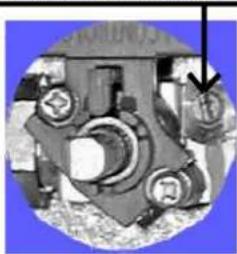
natural_image
Mechanical assembly diagram showing gears and housing components (no text or labels)REGULATING THE MINIMUM FLAME ON THE HOB BURNER
a) Natural gas :
. simply loosen the screw.
. switch on the burner and turn 📋 the knob to minimum.
. Turn the by-pass screw ⏻ until a low flame is visible. Turn the control knob from minimum to maximum position to check that it is satisfactory.
b) Butane-propane gas :
The by-pass screw should be screwed 📋 fully home, without being locked.
THE GAS BURNER
THE VERY FAST BURNER has a power rating of 3,5 kW :
Use the large burner for bringing to the boil, for cooking large quantities, and generally for all foods requiring rapid cooking.
THE FAST BURNER has a power rating of 2,5 kW :
It is ideal for stewing, sauces and slow cooking.
THE SEMI-FAST BURNER has a power rating of 1,45 kW :
Use this small burner for small pans.
For a proper use of the burners, choose pans which match the dimensions given below :
* Very fast ∅ 18 cm and more
* Fast ∅ from 16 to 18 cm
* Semi-fast ∅ 12 cm
SOME TIPS ....
- Pans with curved, ridged or warped bottoms are not recommended.
- Avoid boiling food too intensely. Food is not cooked any more quickly this way. In fact, it is subjected to severe agitation, which may cause the food to lose some of its flavour.
- To save gas, make sure that the flames do not overlap the bottom of the pan.
- Do not use the gas burner with an empty pan.
RECOMMENDATIONS : when the burners are not in service, the general gas supply tap should always be turned off.
THE GAS BURNER
Each burner is controlled by a tap with progressive settings allowing :
* a wider choice of settings from the maximum position to the lowest and most precise one,
* easier flame regulation according to the pan diameter,
* no risk of cutting off the flame or switching off when the flame is turned down quickly.
Each burner is fitted with automatic ignition. The ignition can be made with one hand, while you have the pan in the other hand.
USE :
- Turn on the gas tap,
- A symbol next to each control knob indicates which burner is lit.
Hob with automatic ignition integrated on the knob :
- Press and turn the knob until position "+" keeping it pressed to produce sparks which in turn ignite the burner.
Hob with safety device on the burner and automatic ignition integrated on the knob :
The thermocouple fast safety is a device allowing the automatic cut-out of the gas supplying on the burner, in case the flame dies out accidentally.
- Press and turn the knob to position "+" keeping it pressed to produce sparks which in turn ignite the burner. Keep the pressure on the control knob a few seconds to permit the releasing of the safety device.
- Set the flame according to your cooking requirements. Intermediate positions are available between the "+" and "-" settings on the control knob.
- To turn the flame out, turn the control knob back to stop position.
Please note :
If there is a power cut, the burner can be ignited by pressing in and turning the knob to position "+" and holding a naked flame to the burner.
THE HOT PLATE
THE SPEED PROTECTED HOT PLATE (2000 W) fitted to the mixed hob is located at the rear left.
This is a cast-iron hot plate, controlled by a 7 position switch.
An internal thermostat cuts off part of the power supply if overheating occurs. (if, for example, a hot plate is working without a pan on it).
BEFORE USING THE ELECTRICAL HOT PLATE :
- Before using the electric hot plate for the first time, let it heat up for a few minutes, without a pan, at maximum temperature to allow the protective coating to harden.
HOW TO USE :
- For best results, it is advisable to start on the maximum heat and then turn back to an intermediate temperature taking into account the type and volume of the food.
- An indicator light comes on to show that the hot plate is operating.
- To switch off, turn the knob back to point "●".
DIFFERENT TEMPERATURE SETTINGS :
Below are a few examples which are given as guidelines. When you become more familiar with the appliance, you will be able to choose settings to suit your own personal tastes and requirements.
| snoitisoP | Some tips ..... | |
| 1 | Very low | To keep a dish hot, melt butter and chocolate .... |
| 2 | ow | Slow cooking, sauces, stews, rice pudding, poached eggs ... |
| 3 | Moderately | Beans, frozen foods, fruit, boiling water .... |
| 4 | Medium | Steamed apples, fresh vegetables, pasta, crepes, fish .... |
| 5 | High | More intense cooking, omelettes, steaks .... |
| 6 | Very high | Steaks, chops, frying... |
Cooking with the electrical hot plate
To get the best results from your appliance it is important to observe the following :
- Use thick, flat-based cooking vessel:
a completely flat base prevents overheating to certain parts which causes food to stick. Thick metal allows for good heat distribution.
• Make sure that the base of the pan is dry : this will prevent sticking to the hot plate caused by moisture. - Use pans with a diameter large enough to completely cover the hot plate, otherwise energy will be wasted and any spillages will cause the hot plate to become stained and will become difficult to maintain (rust, etc.).
- Never leave a hot plate switched on without a pan on it: it can be damaged, which would reduce its efficiency.
- When cooking with fat or oil, never leave the hob unattented, very hot fats and oils can quickly catch fire.
- When the hot plate is hot, avoid any contact with materials made of plastic or aluminium foil.
Caution : the heating surfaces clearly get hot while operating, so make sure that small children are kept well away from the hob.
CLEANING
Before cleaning or removing the hob, it is imperative to :
. disconnect the hob from the mains supply,
. let all parts of the hob cool down.
Never use :
harsh abrasives, scouring pads or sharp objects to clean the hob.
• GENERAL MAINTENANCE
THE HOB
. Enamelled steel hob : when the hob has cooled completely, simply clean the enamelled hob with soapy water, rinse and wipe with a clean dry cloth. If you clean the enamelled hob when it is hot, you may tarnish it.
. Stainless steel : clean with soapy water, rinse and dry. You can use a special product to clean stainless steel which is available from various retail outlets.
THE KNOBS -
Only clean with soapy water, rinse and dry well.
THE GAS BURNERS
For cleaning, it is recommended to remove all greasy or burnt deposits with ammonia based products or usual cleaning products.
• The burner cap : it is simply placed on the burner.
Remove the pan support, the burner cap and clean it with a slightly soapy sponge. Rinse and dry.
The enamelled steel burner cap : do not immerse it in cold water when it is hot, this will prevent the enamel cracking as a result of thermal shock.
The brass finish burner cap : on using, the burner cap surface looses its brightness. For current cleaning, it is recommended to remove all greasy or burnt deposits with ammoniacal products or usual cleaning products. To recove brass brightness, use a special cleaning product for copper, brass or bronze currently sold in stores. Do not use this specific product for cleaning of the knobs.
- The burner body: regular cleaning will maintain the appliance original appearance.
Clean with a soapy sponge, rinse and dry. If the holes become clogged, brush the caps using soapy water and dry with a clean cloth.
When re-assembling the burners, make sure that the burner caps and the burners themselves are dry and after, seat them correctly.
Be careful not to let any water get into the burners.
CLEANING
THE PAN SUPPORT
Depending on the model, the pan supports are made of chrome steel, enamelled steel or cast-iron.
They are simply placed on the hob. Lift them up to remove them.
For the maintenance of the pan support, never use harsh abrasives, scouring pads or sharp objects as this will cause irreparable damage to the enamel.
When the pan support is cold, simply clean with soapy water, rinse and dry with a clean cloth.
THE HOT PLATE
To burn off any cooking deposits heat the hob for a short time. After switching off and the hot plate has cooled down, wipe it with absorbent paper. It is important that the hot plate is protected from moisture.
Do not use abrasive products.
To maintain and preserve its appearance, rub a drop of neutral oil, such as sewing machine oil into the surface of the hot plate.
The hot plate should always be dry, or slightly greasy. If it is not to be used for some time, remove any rust using emery paper followed by a suitable commercially available product for the maintenance of soil hotplates.
TECHNICAL DATA
GAS HOBS :
. TC 40 - TCS 40 - TT 40 - TR 40
Gas total power : 9,95 kW
G 20 20 mbar : 947 l/h
G 30 28-30 mbar : 725 g/h
G 31 37 mbar : 712 g/h
MIXED HOBS :
. TC 31 - TCS 31 - TT 31 - TR 31
Electrical total power : 2 kW
Gas total power : 7,45 kW
G 20 20 mbar : 709 l/h
G 30 28-30 mbar : 543 g/h
G 31 37 mbar : 533 g/h
In order to improve the quality of the products, ROSIERES may carry out modifications linked to technical improvements.

Appliance meeting with the standard CEE 89/336, 73/23 and 90/396.
ÍNDICE
natural_image
Line drawing of a room interior with brick wall, cabinet, and window (no text or symbols)natural_image
Line drawing of a kitchen sink with a lamp and brick wall, no text or symbols presentALLACCIAMENTO : "PARTE A GAS"
- ALLACCIAMENTO CON TUBO FLESSIBLE IN ACCIAIO
natural_image
Mechanical assembly diagram showing gears and shafts in a circular frame (no text or labels)REGOLAZIONE DEL BRUCIATORE DEL PIANO DI COTTURA
a) gas naturale :
natural_image
Diagram of a roof structure with triangular roof and diagonal braces, no text or symbols presentIncasso : TIPO X (Norma CEI 335-2-6)