
VT1512IP - Power strip Panamax - Free user manual and instructions
Find the device manual for free VT1512IP Panamax in PDF.
| Product Type | Power strip with conditioner and sequencer |
| Brand | Panamax |
| Model | VT1512IP |
| Dimensions (L x W x H) | 94 cm x 4.5 cm x 4.5 cm |
| Weight | 2.65 kg |
| Power supply | 120 VAC, 50/60 Hz |
| Current capacity | 15 A (1800 W) |
| Number of outlets | 12 outlets (3 spaced for wall adapters, 6 rotated 90°) |
| Power cord length | 3 m (10 ft) with detachable NEMA 5-15P plug |
| Surge protection | Yes (Protect-or-Disconnect, 3,000 A rating, 200 V peak clamping level) |
| RFI/EMI filtering | Standard (18 dB at 100 kHz, 53 dB at 1 MHz) |
| Load disconnect (over/under voltage) | Yes (thresholds: >140 VAC or <85 VAC) |
| Power sequencing | Yes (12 sequenced outlets, programmable delays) |
| IP control and monitoring | Via BlueBOLT (Web and cloud interface) |
| Network connectivity | Ethernet (RJ45), UDP protocol (port 57010) |
| Circuit breaker | Yes, 15 A resettable |
| Ground lug | Yes, for Panamax signal line protection modules |
| Mounting | Vertical rack mount (brackets included) |
| Warranty | 3-year limited product warranty |
| Connected equipment protection policy | $5,000,000 (with Panamax line protection modules) |
Frequently Asked Questions - VT1512IP Panamax
User questions about VT1512IP Panamax
0 question about this device. Answer the ones you know or ask your own.
Ask a new question about this device
Download the instructions for your Power strip in PDF format for free! Find your manual VT1512IP - Panamax and take your electronic device back in hand. On this page are published all the documents necessary for the use of your device. VT1512IP by Panamax.
USER MANUAL VT1512IP Panamax
VT1512-IP Custom Install Power Management
VT1512-IP
A BlueBOLT® Enabled Vertical Rack Power Conditioner with 12 Outlets
CUSTOM INSTALL POWER MANAGEMENT
Congratulations on your purchase of the Panamax VT1512-IP BlueBOLT enabled vertical rack power conditioner and power sequencer. The VT1512-IP is a full featured power conditioner providing protection and filtration for maximum longevity and performance of connected equipment. BlueBOLT enabled, the VT1512-IP allows remote reboot of 12 individually controlled outlets, as well as the ability to monitor energy use, set alerts, program scheduled commands, network pings with conditional reboot and much more.
FEATURES
- Protect-or-Disconnect surge protection
• Standard EMI/RFI Filtration
• Over/Under voltage load disconnect - Power Sequencing
- IP Monitor & Control - BlueBOLT™ enabled for IP control and monitoring
• 12 individually controlled outlets, 3 spaced for wall-warts & 6 turned 90°
• Ground lug to attach Panamax signal-line protection modules - Sleek design ideal for vertical mounting to an equipment rack with included brackets
• 10 foot power cord with removable plug to customize length
• 15A Capacity with circuit breaker
• 3 year limited product warranty - \$5,000,000 Connected Equipment Protection Policy when used with Panamax signal-line protection modules.
Important: You will need the VT1512-IP's unique MAC Address and Challenge Key (provided on the 2 labels attached to the cover of this guide, as well as on a label on the bottom of the product) to register the unit for control and monitoring at www.mybluebolt.com. One is permanently adhered and the other is removable for your convenience.
You can find the VT1512-IP manual on the product page at www.panamax.com under the Resource tab.
IMPORTANT SAFETY INSTRUCTIONS
- Read these instructions.
- Keep these instructions.
- Heed all warnings.
- Follow all instructions.
- WARNING: Do not use this apparatus near water. To reduce the risk of fire or electric shock, do not expose this apparatus to rain or moisture.
- CAUTION - Could Contain Always On Receptacles (depending on BlueBOLT programming). To reduce risk of shock - Disconnect VT1512-IP from power source before servicing any equipment connected to VT1512-IP.
- Clean only with dry cloth.
- Do not install near any heat sources such as radiators, heat registers, stoves, or other apparatuses that produce heat.
- Do not defeat the safety purpose of the polarized or grounding type plug. A polarized plug has two blades, with one wider than the other. A grounding type plug has two blades and a third grounding prong. The wide blade or the third prong is provided for your safety. If the provided plug does not fit into your outlet, consult an electrician for replacement of the obsolete outlet.
- Protect the power cord from being walked on or pinched, particularly at plugs, convenience receptacles, and the point where they exit from the apparatus.
- Only use attachments/accessories specified by the manufacturer.
- Refer all servicing to qualified service personnel. Servicing is required when the apparatus has been damaged in any way, such as power-supply cord or plug is damaged, liquid has been spilled or objects have fallen into the apparatus, the apparatus has been exposed to rain or moisture, does not operate normally, or has been dropped.
- Where the power cord is used as the main disconnect device, the disconnect device shall remain readily accessible.
- This device must be connected to a main socket outlet with a protective earthing (ground) connection.

MODEL: VT1512-IP
Inspect the unit upon receipt. In addition to this guide, the box should contain the following:

PANAMAX
www.panamax.com
Instruction Manual
Table of Contents
VT1512-IP Instruction Manual-English 2
Mounting....2 BlueBOLT®....2
Product Features .... 3
Advanced Operations 4 VT1512-IP Advanced Operation 4
Status 4
Controls 4
Configuration....4
Message Types 5
Common Attributes 7
Query Commands 7
Action Commands 9
Password Protection....12
Troubleshooting 13
VT1512-IP Specifications 14
Technologies....15
Warranty Information 16
Limited Three Year Warranty....16
FCC Notice 16
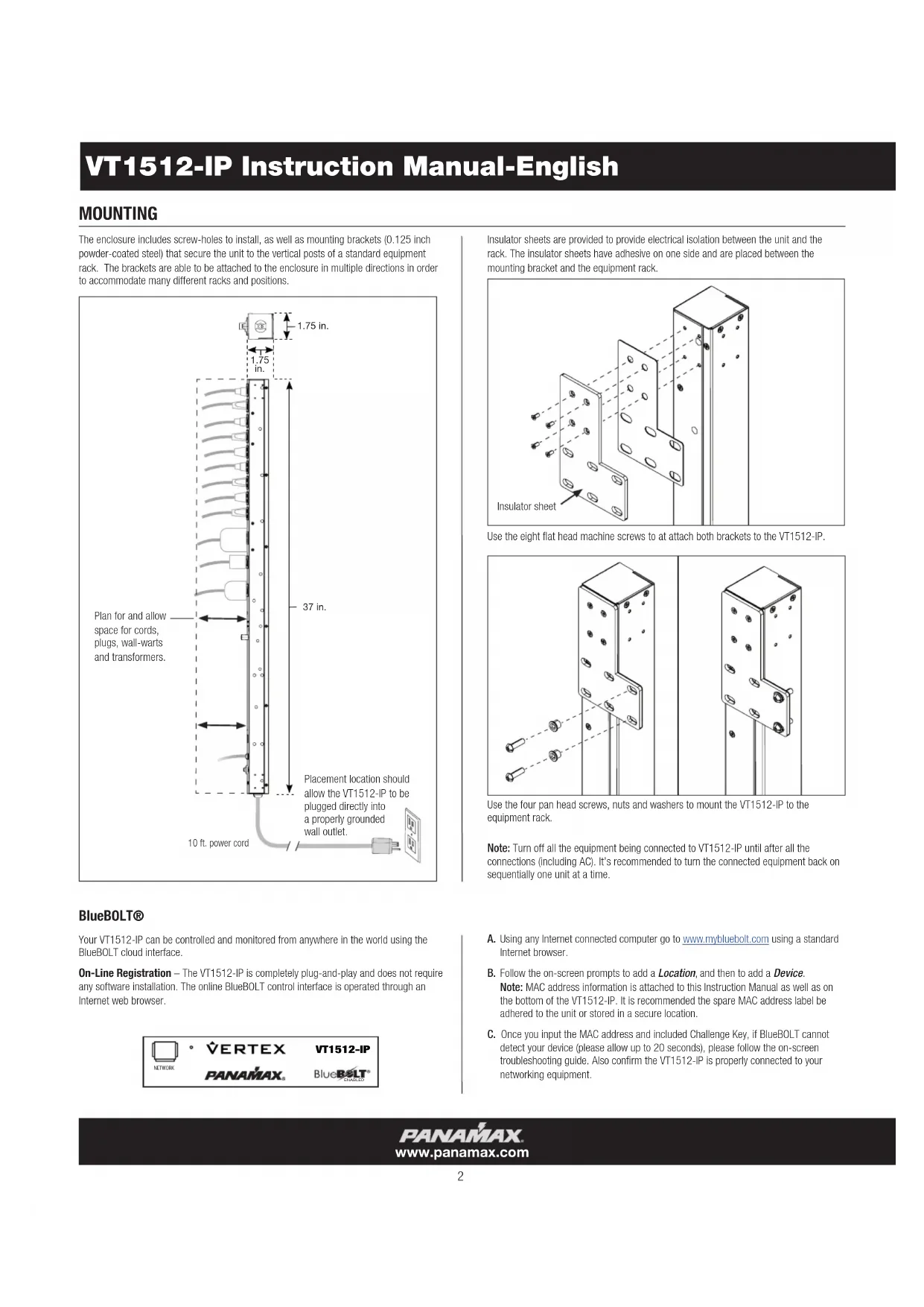
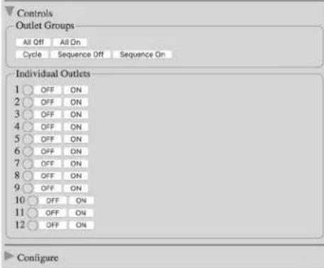
The enclosure includes screw-holes to install, as well as mounting brackets (0.125 inch powder-coated steel) that secure the unit to the vertical posts of a standard equipment rack. The brackets are able to be attached to the enclosure in multiple directions in order to accommodate many different racks and positions.

Insulator sheets are provided to provide electrical isolation between the unit and the rack. The insulator sheets have adhesive on one side and are placed between the mounting bracket and the equipment rack.
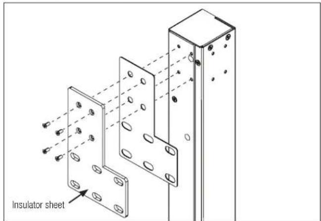
Use the eight flat head machine screws to at attach both brackets to the VT1512-IP.
natural_image
Technical line drawing of two mechanical bracket components with mounting holes and bolted joints (no text or symbols)Use the four pan head screws, nuts and washers to mount the VT1512-IP to the equipment rack.
Note: Turn off all the equipment being connected to VT1512-IP until after all the connections (including AC). It's recommended to turn the connected equipment back on sequentially one unit at a time.
BlueBOLT®
Your VT1512-IP can be controlled and monitored from anywhere in the world using the BlueBOLT cloud interface.
On-Line Registration – The VT1512-IP is completely plug-and-play and does not require any software installation. The online BlueBOLT control interface is operated through an Internet web browser.
A. Using any Internet connected computer go to www.mybluebolt.com using a standard Internet browser.
B. Follow the on-screen prompts to add a Location, and then to add a Device.
Note: MAC address information is attached to this Instruction Manual as well as on the bottom of the VT1512-IP. It is recommended the spare MAC address label be adhered to the unit or stored in a secure location.
C. Once you input the MAC address and included Challenge Key, if BlueBOLT cannot detect your device (please allow up to 20 seconds), please follow the on-screen troubleshooting guide. Also confirm the VT1512-IP is properly connected to your networking equipment.
PRODUCT FEATURES
PANAMAX
www.panamax.com
VT1512-IP Instruction Manual - English
ADVANCED OPERATIONS
VT1512-IP Advanced Operation
The VT1512-IP has an embedded web page for users that wish to use the VT1512-IP on a LAN. The embedded webpage displays the units' serial number, ethernet address (MAC ID), firmware version, bootcode version and brand and model number. To find the VT1512-IP IP address, you can claim the device in BlueBOLT one time and look under Device ADMIN for the IP address or you can use your networking devices. In some cases, your ISP modem may be equipped with a tool to locate the IP address of the VT1512-IP.
BlueBOLT Configuration Interface
Serial Number: PA01031X142193100007
Ethernet Address: 1065a3051973
Firmware Version: 1.0.5.190930
Bootcode Version: 1.4.1
Model: Panamax VT1512-IP
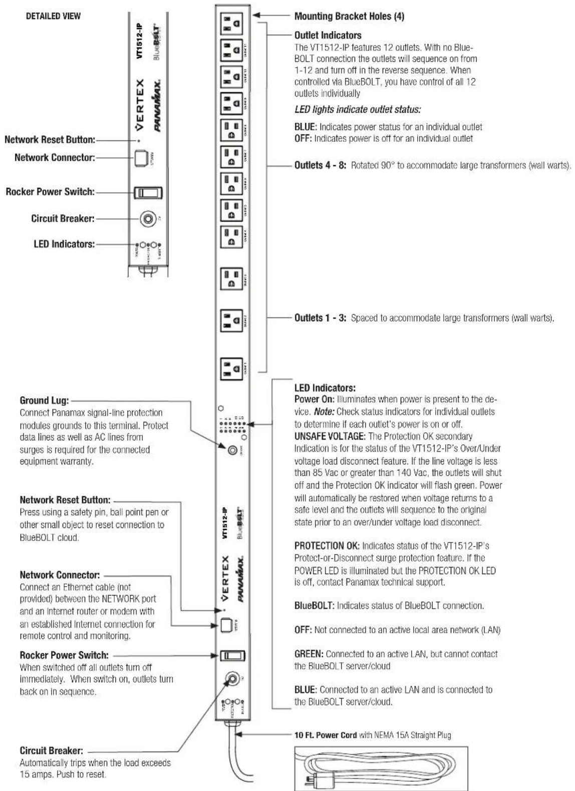
Status
The Status screen shows you the integrity of the power: Voltage, Amperage, Wattage, Power Factor and Power VA. The Conditions screen displays the Power Condition (detailed below), whether the Breaker is "opened" or "closed" and if the Voltage Monitoring is working.
Power Condition States
Normal = Input voltage is within range
Undervoltage = The voltage is so low that the over/under voltage load disconnect has engaged and all outlets are off.
Overvoltage = The voltage is so high that the over/under voltage load disconnect has engaged and all outlets are off.
Recovery = Recovery
- Recovering from an over/under voltage load disconnect condition
- Recovering after the breaker has been tripped and reset
- Recovering after the switch has been turned off and turned on again or a power cycle
- Recovery will also be stated when the unit is plugged into a live AC source.
Voltage Monitor States
Voltage Monitor = okay - voltage is within a safe range
Voltage Monitor = fault
- Either the over/under voltage load disconnect has engaged and all outlets are off.
- The breaker was tripped turning all outlets off
- The power switch was turned off, turning all outlets off.
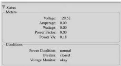
Controls
The Controls screens allows you to see which outlet(s) is On or Off. It allows you to sequence the unit On and Off or cycle group. You can turn all outlets On sequentially as programmed and Off immediately (no sequence).
Configuration
The Configuration screen is used to set up your password protection, set the IP as Static or DHCP (default) and configure advanced device settings.
The Advanced Device settings allow you to program which outlets get sequenced, program which outlets are part of a group cycle and sequence delays.
The VT1512-IP can be interfaced with Control and Automation systems on the local area network. All messages are encapsulated in standard XML format and are sent and received over UDP port 57010. The XML version declaration, , is at the beginning of each message. Each message must have a single root element. Messages that do not conform to the standard will be ignored. A convenient way to test messages is the "netcat" tool, available for Windows 10, Linux and Unix.
?xml version="1.0"?
The root element for all messages is named "device". The device element must have two attributes, "class" and "id". The class attribute specifies the type of device (model) and must be "vt1512". The "id" attribute is the unique device ID (its Ethernet MAC address), expressed with lower case letters and no formatting. For example:
1. Command Messages
Command messages are sent to the VT1512-IP in order to have it perform a task. The task can be to perform a physical action, such as switching an outlet (referred to as an "action"). When the task is to transmit data, such as device status, it is referred to as a "query". Whether the task is an "action" or "query", the message is classified as a command and is contained within the
Example Action Command Message - switch outlet 2 to OFF:
<?xml version="1.0"?>
<device class="vt1512" id="1065a3051970">
<command><outlet id="2">0</outlet></command>
</device>
2. Response Messages
In response to a query command, the VT1512-IP will send a reply message. The contents part of the message will be a set of elements enclosed in either the
Example Response Message- response to "sendinfo" query command:
<?xml version="1.0"?>
<device class="vt1512" id="1065a3051970">
<command><sendinfo></command>
</device>
This would be considered the "envelope" for all messages, where the “...” is to be considered the "contents" of the message. Since all messages include the "envelope", message details will only document the "contents".
Message Types
There are three types of messages: command messages, response messages and event messages.
<?xml version="1.0"?>
<device class="vt1512" id="1065a3050000">
<command><outlet id="2">0</outlet></command>
</device>
By default, the VT1512-IP does not respond to action command messages.
Example Query Command Message – send information
<?xml version="1.0"?>
<device class="vt1512" id="1065a3050000">
<command><sendinfo></command>
</device>
Response
<?xml version="1.0" ?>
<device class="vt1512" id="1065a3050000">
<info time="1234567890">
<sernum>PAVT1512PR00X142160000000</sernum>
<fwver>1.0.0.12520</fwver>
<bootcodever>1.0</bootcodever>
<ipaddr>3194548209</ipaddr>
<coprocfwver>1.0.0.12520</coprocfwver>
<coproclot>1300795003</coproclot>
<coprocdiex>5</coprocdiex>
<coprocdiey>42</coprocdiey>
<coproctest>65272</coproctest>
</info>
</device>
Response messages can be used to verify command message delivery. If a verifiable response message is desired from the VT1512-IP, the optional "xid" attribute is included in the
Example 1:
Action Command Message with xid –
<?xml version="1.0"?><device class="vt1512" id="1065a3050000">
<command xid="123"><outlet id="1">0</outlet></command></device>
Response Message with ack –
<?xml version="1.0"?><device class="vt1512" id="1065a3050000"><ac

VT1512-IP Instruction Manual - English
Example 2:
Query Command Message with xid –
?xml version="1.0"?
Response Message with ack –
?xml version="1.0"?
3. Event Messages
Event messages are sent when a change of device status or settings occurs. The
Example Event Message - outlet 3 switched to ON:
?xml version="1.0"?
Element Description
dlys required delays container.
dly outlet delays - attributes represent: "id" = outlet number, "sf" = power sequence off delay, "so" = power sequence on delay,
"cy" = power cycle delay. All delays values are in seconds, 255 seconds maximum.
grps required groups container.
sq opt-in/opt-out of sequence group: hexadecimal value represents which outlet participate in power sequence group. See above for details.
cy opt-in/opt-out of power cycle group: hexadecimal value represents which outlet participate in power cycle group. See above for details.
Outlet number Outlet group hex code Binary
| Outlet Hex Binary | |
| 1 001 0000 0000 0001 | |
| 2 002 0000 0000 0010 | |
| 3 004 0000 0000 0100 | |
| 4 008 0000 0000 1000 | |
| 5 010 0000 0001 0000 | |
| 6 020 0000 0010 0000 | |
| 7 040 0000 0100 0000 | |
| 8 080 0000 1000 0000 | |
| 9 100 0001 0000 0000 | |
| 10 200 0010 0000 0000 | |
| 11 400 0100 0000 0000 | |
| 12 800 1000 0000 0000 |
1 through 12 (i.e., all twelve outlets) fff 1111 1111 1111
1, 3, 6 and 7 (i.e., four outlets) 065 0000 0110 0101
Settings-related messages (i.e.,
Details -
Common Attributes
Some message elements will include a timestamp attribute "time". The timestamp is in standard UNIX time, up to 10 decimal digit characters, and represents the number of seconds that have passed since January 1st 1970 GMT.
Some message elements involve a group of outlets. Outlet group values are given as hexadecimal digits, representing which outlets participate in the group. A group value is encoded in a 12-bit binary bitmap, using the hexadecimal digits. To process the data it must be converted from hexadecimal to binary, where each bit represents an outlet participating in the group. Bit 0 represents outlet #1. The following table should help clarify:
<dlys>
<dly id="1" sf="12" so="1" cy="10"/>
<dly id="2" sf="11" so="2" cy="10"/>
<dly id="3" sf="10" so="3" cy="5"/>
<dly id="4" sf="9" so="4" cy="10"/>
<dly id="5" sf="8" so="5" cy="10"/>
<dly id="6" sf="7" so="6" cy="10"/>
<dly id="7" sf="6" so="7" cy="15"/>
<dly id="8" sf="5" so="8" cy="10"/>
<dly id="9" sf="4" so="9" cy="10"/>
<dly id="10" sf="3" so="10" cy="10"/>
<dly id="11" sf="2" so="11" cy="15"/>
<dly id="12" sf="1" so="12" cy="10"/>
</dlys>
<grps>
<sq>13f</sq>
<cy>f35</cy>
</grps>
Where "id" is the outlet number, "sf" is the turn off delay, "so" is the turn on delay and "cy" is the power cycle delay. The designation "sq" is the bitmap for outlets to be sequenced, and "cy" is the bitmap for outlets to be power cycled.
Query Commands
Send Information Query
The Send Information query is used to retrieve general information about the device. Response information elements are enclosed in the
Query -
<sendinfo/>
Sample Response –
<info time="1234567890">
<sernum>PAVT1512PRO0X142160000000</sernum>
<fwver>1.0.0.12520</fwver>
<bootcodever>1.0</bootcodever>
<ipaddr>3194548209</ipaddr>
<coprocfwver>1.0.0.12520</coprocfwver>
<coproclot>1300795003</coproclot>
<coprocdiex>5</coprocdiex>
<coprocdiey>42</coprocdiey>
<coproctest>65272</coproctest>
</info>
Details –
Element Description
sernum serial number of the product.
fwver version of firmware running on the master processor.
bootcodever version of boot loader firmware running on the master processor.
ipaddr Internet Protocol address in use, decimal value.
coprocfwver version of firmware running on the co-processor.
All other elements are for Core Brands use only.
Send Status Query
The Send Status query is used to retrieve the device status. Response status elements are enclosed in the
Query -
<sendstatus/>
VT1512-IP Instruction Manual - English
Sample Response –
<status time="1234567890">
<voltage>119.14</voltage>
<voltpeak time="0">0.00</voltpeak>
<amperage>0.00</amperage>
<wattage>0.00</wattage>
<pwrva>0.15</pwrva>
<pwrfact>0.00</pwrfact>
<pwrcond>0</pwrcond>
<brkrfault>0</brkrfault>
<lastseqstate>1</lastseqstate>
<seq>0</seq>
<cycprog>0</cycprog>
<coprocop>1</coprocop>
<coproclink>1</coproclink>
<coprocimp>0</coprocimp>
<coproccrcerrs>0</coproccrcerrs>
<crcerrs>2</crcerrs>
<outlet id="1">1</outlet>
<outlet id="2">1</outlet>
<outlet id="3">1</outlet>
<outlet id="4">1</outlet>
<outlet id="5">1</outlet>
<outlet id="6">1</outlet>
<outlet id="7">1</outlet>
<outlet id="8">1</outlet>
<outlet id="9">1</outlet>
<outlet id="10">1</outlet>
<outlet id="11">1</outlet>
<outlet id="12">1</outlet>
<tfflestate len="0" chk="4294967295
</status>
Details –
Element Description
voltage measured RMS line voltage, 1 Vac precision. voltpeak measured peak voltage, 1 Vac precision. "time" attribute represents time of occurrence. amperage measured total load current, 0.1 Ampere precision. wattage measured total power consumption, 1 Watt precision. pwrva measured volt-ampere consumption, 1 VA precision. pwrfact measured load power factor, 0.01 precision. pwrcond power condition: 0 = normal; 1 = fault recovery; 2 = under voltage; 3 = over voltage. seq power sequence state: 0 = no sequence; 1 = sequencing ON; 2 = sequencing OFF. cycprog group power cycle operation state: 0 = no cycle in progress; 1 = cycle in progress. outlet state: 0 = outlet OFF; 1 = outlet ON. "id" attribute's decimal value represents outlet number.
All other elements are for Nortek Security & Control use only.
Send Settings Query
The Send Settings query is used to retrieve the device configuration settings. Response settings elements are enclosed in the
Query —
Sample Response –
... (see Common Attributes section) ...
Details –
Element Description
settings device configuration settings. See Common Attributes section for details.
Action Commands
Switch Outlet Action
The Switch Outlet action is used to turn ON or turn OFF an outlet.
Sample Action –
<outlet id="2">0</outlet>
Details –
Element Description
outlet switch outlet: 0 = outlet OFF; 1 = outlet ON. The "id" attribute indicates which outlet, decimal number 1-12.
Switch Outlet Group Action
The Switch Outlet Group action is used to turn ON or turn OFF an outlet group.
Sample Action –
<outlets grp="c3">1</outlets>
Details -
Element Description
outlets switch outlet group: 0 = outlets OFF; 1 = outlets ON. The "grp" attribute indicates which outlets participate in the group, using hexadecimal digits. See Common Attributes section for details.
Cycle Outlet Action
The Cycle Outlet Group action is used to power cycle an outlet group. Each outlet power cycle delay is defined in the device configuration settings. See Common Attributes section for details.
Sample Action –
<cycleoutlet id="2"/>
Details –
Element Description
"cycleoutlet" power cycle outlet. The "id" attribute indicates which outlet, decimal number 1-12.
Cycle Outlet Group Action
The Cycle Outlet Group action is used to power cycle an outlet group. Each outlet power cycle delay is defined in the device configuration settings. See Common Attributes section for details.
Sample Action –
<cycleoutlets grp="1c3"/>
Details –
Element Description
"cycleoutlets" power cycle a group of outlets. The "grp" attribute indicates which outlets participate in the group, using hexadecimal digits. See Common Attributes section for details.
Cycle Predefined Outlet Group Action
The third method for cycling outlets relies on the cycle group already defined by the set cycle group command (see: Set Settings Action). Otherwise, this command behaves identically to the other two cycle commands. See Common Attributes section for details.
Sample Action –
<cyclegrp/>
Sequence Action
The Sequence action is used to initiate a power sequence of an outlet group. The power sequence outlet group and each outlet sequence on and sequence off delays are defined in the device configuration settings. See Common Attributes section for details.
Sample Action —
<sequence>0</sequence>
Details –
Element Description
sequence power sequence outlet group: 0 = power OFF sequence; 1 = power ON sequence.
Subscribe Action
The Subscribe action is used to subscribe to device events.
Sample Action –
<eventmgr>
<subscribe uri="ctrlsys://127.0.0.1:12345"/>
</eventmgr>
VT1512-IP Instruction Manual - English
Details –
Element Description
"eventmgr" required container.
Subscribe "subscribe" to device events. "uri" attribute is formatted as "ctrlsys://IPADDR:PORT", where IPADDR:PORT is the Internet Protocol address and UDP port number where event messages should be sent. It may be a different IP address than the control system which sent the request. NOTE: Only one IP address / port event subscription is allowed.
Unsubscribe Action
The Subscribe action is used to unsubscribe to device events.
Sample Action –
<eventmgr>
<unsubscribe uri="ctrlsys://127.0.0.1:12345"/>
</eventmgr>
Details —
Element Description
"eventmgr" required container.
Unsubscribe "unsubscribe" to device events. "uri" attribute is formatted as "ctrlsys://IPADDR:PORT", where IPADDR:PORT is the Internet Protocol address and UDP port number where event messages have been sent. It may be a different IP address than the control system which sent the request.
Events
By default, the VT1512-IP will not send any event messages. To receive event messages a Subscribe Action must be sent after each device reset, reboot or power up.
See Subscribe Action section for details.
Event messages will be repeated by the device until an acknowledgement message is sent back to the VT1512-IP, or after a timeout period of approximately 20 minutes. The acknowledgement message must contain the same "evtid" and "subsid" attribute values as the event message.
Sample Acknowledgement Message –
<eventmgr>
<ack evtid="123" subsid="1">
</eventmgr>
Details –
Element Description
"eventmgr" required container. Acknowledgement "ack" of device event. "evtid" attribute represents device event number, "subsid" attribute represents subscriber number. Both attributes must contain the same values as the event message.
Outlet State Event
The Outlet State event is posted when an outlet changes from ON to OFF, or vice versa.
Sample Event –
<outlet id="1">1</outlet>
Details –
Element Description
Outlet "outlet" state: 0 = outlet now OFF; 1 = outlet now ON. The "id" attribute indicates which outlet changed state, decimal value 1-12.
The Sequence event is posted when a power on or power off sequence is initiated or completed.
Sample Event –
<seq>2</seq>
Details –
Element Description
"seq" power sequence state: 0 = sequence completed; 1 = sequence ON initiated; 2 = sequence OFF initiated
Power Condition Event
The Power Condition event is posted when device enters or recovers from over-voltage or under-voltage shutdown mode.
Sample Event –
<powercond>3</powercond>
Details -
Element Description
powercond power condition: 0 = now normal; 1 = now fault recovery; 2 = now under voltage; 3 = now over voltage.
Settings Event
The Settings event is posted when the device's configuration settings change. Information for all settings is transmitted, not just for the individual settings that changed.
Sample Event –
... (see Common Attributes section) ...
Details —
Element Description
Set device configuration settings. See Common Attributes section for details.
Scheduled Action Fired Event
A Scheduled Action Fired event is posted when the device performs a scheduled operation.
Sample Event –
Details —
Element Description
schedmgr container identifies event as a scheduled action.
fire container identifies scheduled action as fired.
day the scheduled days of the week to fire the command. See table below for encoding details.
min the scheduled minute of the day (since midnight) to fire the command.
command container identifies the action command. See Action Commands section for details.
The
Scheduled day(s) of the week days of week Binary
Thursday 1 0000001
Friday 2 0000010
Saturday 4 0000100
Sunday 8 0001000
Monday 16 0010000
Tuesday 32 0100000
Wednesday 64 1000000
Monday – Friday 115 1110011
Saturday-Sunday 12 0001100
VT1512-IP Instruction Manual - English
PASSWORD PROTECTION
Once you have claimed your VT1512-IP, you can set up password protection. To do so you need to enter the Local IP address of the VT1512-IP card into your browser. You can locate the Local IP Address by clicking on Device Admin within the BlueBOLT user interface. This will take you to the embedded web page of the VT1512-IP.
Note: You must be on the same network as the VT1512-IP to view the embedded web page.
BlueBOLT Configuration Interface
Serial Number: PA01031X142193100007
Ethernet Address: 1065a3051973
Firmware Version: 1.0.5.190930
Bootcode Version: 1.4.1
Model: Panamax VT1512-IP
Once you are logged into the embedded webpage of the VT1512-IP click on Configuration.
Input a user name and password, check the box for "Password Protection Enabled", and click the "Update Password" button.
Controls
Configure
Network
Password Protection Enabled
Username: admin
Password: ....
Update Password Protection
DHCP
IP Address:
Network Mask:
Gateway Address:
Static
IP Address: 172.16.117.170
Network Mask: 255.255.255.128
Gateway Address: 172.16.117.129
Update IP Address
Once you have enabled the password protection, your browser will prompt you to sign in using the new admin and password. Depending on your browser, you may need to refresh the page if the log in screen flashes.
Configure
Network
Password Protection Enabled
Username: admin
Password: ....
Update Password Protection

Authentication Required
http://172.16.117.170 is requesting your username and password. The site says: "Restricted Content"
User Name:
Password:
Cancel
OK
TROUBLESHOOTING
GENERAL USE:
| My equipment doesn’t turn on. | Make sure that the VT1512-IP is plugged into a working AC outlet. Check all AC connections. Make sure VT1512-IP and connected equipment are turned on. Confirm “POWER ON” and individual outlet status LEDs are illuminated. Check to see if the circuit breaker on the VT1512-IP needs to be reset (press in). |
| The VT1512-IP circuit breaker disconnects AC power from the connected equipment. | You have exceeded the ampere rating for your VT1512-IP. As a temporary fix, disconnect one or more pieces of equipment. Ask you dealer about additional PANAMAX products that may be required. |
| There is no picture or sound on my TV. | Ensure that the TV set is plugged into a powered AC outlet.Check the appropriate connections to ensure that they are correctly and securely installed. |
BlueBOLT/Network connectivity:
Check these steps when having issues with BlueBOLT connectivity:
| Is the VT1512-IP receiving power? Check the power cable and confirm the unit is ON. | |
| Is the BlueBOLT port on the VT1512-IP connected to an active local area network with Internet connectivity? | Check the cables connecting VT1512-IP to the router/switch, cables between the router/switch and modem and the cable connecting the modem to the incoming Internet data jack (coax or DSL) |
| Are the BlueBOLT Link and Activity lights on? | The “Link” light should be illuminated solid green if connected to a LAN or solid blue to active LAN and is connected to BlueBOLT, and the “Activity” light should be blinking intermittently (green). |
| Is your Internet connection functioning? Can you access a general web page through a web browser running on a computer connected to the same local area network? | If you have answered “Yes” to these questions and are still unable to connect the VT1512-IP BlueBOLT, please contact Panamax customer service at 1-800-472-5555. |
VT1512-IP Instruction Manual - English
VT1512-IP SPECIFICATIONS
| AC Power 120Vac 50/60Hz | |
| Total Outlets 12 | |
| Total Current Capacity 15A (1800W) | |
| Voltage Protection Rating (UL 1449 4th Edition, 3,000A) | L-N 500V, L-G 500V, N-G 500V |
| Protection Modes | L-N, L-G, N-G |
| Initial Clamping Level | 200V Peak, 141 RMS |
| Energy Dissipation | 200 Joules |
| Peak Impulse Current | 12,000 |
| Protect-or-Disconnect | Yes |
| Thermal Fusing | Yes |
| Cord Length | Captive 10 ft. cord with removable NEMA 5-15P for length customization |
Environmental Specifications
| Temperature 0°C -+40°C (+32°F - +104°F) | |
| Operating Humidity 0 – 90% non-condensing | |
| Over-voltage load disconnect 140 Vac | |
| Under-voltage load disconnect 85 Vac | |
| Filtration Technology Standard RFI/EMI Filtration | |
| Filtration Rating 18dB @, 100kHz, 53dB @, 1MHz, 18dB – 53dB @, 100kHz – 1MHz |
Product weights and dimensions
| Length 37” | |
| Width 1.75” | |
| Height 1.75” | |
| Weight 5.85lb | |
| UPC 050616010344 |
TECHNOLOGIES
Protect-or-Disconnect
In the event of a catastrophic surge such as lightning, AC power completely disconnects from connected equipment. If such a rare event occurs, the VT1512-IP would require service.
Standard Level RFI/EMI Filtration
The standard level RFI/EMI filter employs a tuned lowpass filter to reduce the differential AC noise coming through your AC power line. The filter reduces the AC line noise on average 18dB @, 100kHz, 53dB @, 1MHz, 18dB - 53dB @, 100kHz - 1MHz.
Over/Under voltage load disconnect
The Over/Under voltage load disconnect circuit constantly monitors the incoming line voltage. If the incoming line voltage becomes dangerously high, it will disconnect the load from the AC input. The high threshold is 140 Vac +/- 2 Vac.
If the incoming line voltage becomes dangerously low, it will disconnect the load from the AC input. The low threshold is 85 Vac +/- 2 Vac.
When the incoming voltage returns to a safe level, the VT1512-IP will automatically turn on and sequence to its original state before the Over/Under voltage event.
Power Sequencing
Some complicated audio & video systems will require power sequencing. The VT1512-IP by default is a power sequencer. Power sequencing allows A/V equipment to be powered up in stages which gives equipment time to stabilize before the next stage of equipment is energized.
When powering down, the sequence order is reversed, which results in a soft landing for your expensive A/V equipment. Power sequencing is also convenient for network devices that requires network "handshakes" to properly communicate with each other.
After applying power to the AC line input and once you turn the power switch on, outlet 1 will turn on immediately. Outlet 2 will turn on 5 seconds after outlet 1, and all other outlets will have a 5 second delay from the power on time of the previous outlet. See defaults below.
Once you claim your VT1512-IP, you can change the default programing to meet your systems requirements and you have complete flexibility. You can keep a 12-step sequence, or keep four outlets powered on and the remaining eight to sequence.
Outlet Sequence Default
| Outlet 1 = 0 second turn on delay, 55 second delay off |
| Outlet 2 = 5 second turn on delay, 50 second delay off |
| Outlet 3 = 10 second turn on delay, 45 second delay off |
| Outlet 4 = 15 second turn on delay, 40 second delay off |
| Outlet 5 = 20 second turn on delay, 35 second delay off |
| Outlet 6 = 25 second turn on delay, 30 second delay off |
| Outlet 7 = 30 second turn on delay, 25 second delay off |
| Outlet 8 = 35 second turn on delay, 20 second delay off |
| Outlet 9 = 40 second turn on delay, 15 second delay off |
| Outlet 10 = 45 second turn on delay, 10 second delay off |
| Outlet 11 = 50 second turn on delay, 5 second delay off |
| Outlet 12 = 55 second turn on delay, 0 second delay off |
IP Monitor and Control
The VT1512-IP can be monitored and controlled via an internal web page for LAN applications, or you can use the BlueBOLT cloud to monitor, control and program your device from anywhere in the world via your computer or mobile device.
VT1512-IP Instruction Manual - English
WARRANTY INFORMATION
CAUTION! WARRANTY LIMITATION FOR INTERNET PURCHASERS
Panamax products purchased through the Internet do not carry a valid Product Warranty or Connected Equipment Protection Policy unless purchased from an Authorized Panamax Internet Dealer and the original factory serial numbers are intact (they must not have been removed, defaced or replaced in any way). Purchasing from an Authorized Panamax Internet Dealer insures that the product was intended for consumer use, has passed all quality inspections and is safe. Buying through auction sites or unauthorized dealers may result in the purchase of salvaged, failed and/or products not intended for use in the US. In addition, Authorized Panamax Internet dealers have demonstrated sufficient expertise to insure warranty compliant installations. For a list of Authorized Panamax Internet Dealers go to www.panamax.com
\$5,000,000 Connected Equipment Limited Protection Policy\*
Signal-line protection modules are required for the connected equipment policy. You can use other Panamax component units our signal-line protection modules. The grounds of the devices must be terminated together. All Panamax Warranties and Connected Equipment Policies are valid only in the United States & Canada.
*Full Warranty and policy Information available at www.panamax.com
Limited Three Year Warranty
What is Covered?
Nortek Security and Control, LLC ("NORTEK SECURITY & CONTROL") warrants to consumers who purchase this product that the product will be free from defects in materials and workmanship for a period of three (3) years (terms will vary depending on product) from the date of purchase. It is not transferable.
If a defect exists, NORTEK SECURITY & CONTROL will have you ship the defective part or product to us and we will, at our option, either repair or replace it. This warranty does not cover the cost of labor to remove a defective part or product or to reinstall any repaired or replacement part or product.
This warranty does not cover defects or damages caused by improper handling, maintenance, storage, installation, removal or re-installation, misuse, non-factory authorized modification or alteration, use of incompatible accessories, impact by foreign objects, accident, fire, acts of God, normal wear and tear or shipping damage other than a shipment from NORTEK SECURITY & CONTROL.
Keep your original sales receipt as it will be required to obtain warranty service. This warranty shall not be extended or restarted upon receipt of any repaired or replacement part or product under this warranty. No person is authorized to extend or otherwise modify this warranty.
Limitations
THE DURATION OF ANY IMPLIED WARRANTY, INCLUDING THE WARRANTIES OF MERCHANTABILITY AND FITNESS FOR A PARTICULAR PURPOSE, SHALL NOT EXCEED THE WARRANTY PERIOD PROVIDED HEREIN.
Some states do not allow limitations on how long an implied warranty lasts, so the above limitation may not apply to you.
NORTEK SECURITY & CONTROL SHALL NOT BE LIABLE FOR ANY INCIDENTAL OR CONSEQUENTIAL DAMAGES RESULTING FROM THE BREACH OF ANY WRITTEN OR IMPLIED WARRANTY.
Some states do not allow the exclusion or limitation of incidental or consequential damages, so the above limitation or exclusion may not apply to you.
This warranty gives you specific legal rights, and you may also have other legal rights which vary from State to State.
How do I Obtain Warranty Service?
Customers in the United States
To obtain warranty service, email our Returns Department at returns@corebrands.com. Include your name, address, telephone number, the model number of your product, a copy of your original sales receipt, and a description of the problem. Unless we need to discuss the situation further with you, you will be emailed a Return Authorization Number and shipping instructions. If we need to discuss the situation further with you, we will call or email you. NORTEK SECURITY & CONTROL may require troubleshooting on installed product before a Return Authorization Number is issued. Anything shipped to us without a Return Authorization Number will be automatically returned unopened. You are responsible for the charges for shipment to us.
Customers outside of the United States
For customers outside of the United States, you are required to address any warranty service requests to the dealer from which you purchased the Nortek Security and Control product or the distributor that supplied such product.
For purchasers whose warranty rights are governed by the consumer protection laws or regulations of a country other than the U.S., the benefits conferred by this warranty are in addition to any conferred by such other laws or regulations, and any limitations of rights stated in this warranty may or may not apply.
Advanced Operation
Besides providing access to Panamax/Furman's hosted BlueBOLT platform, VT1512-IP also supports the following networking protocols. Refer to the Advanced Networking section of the Links and Resources at www.mybluebolt.com.
UDP (Port # 57010) for machine-to-machine communication for interfacing to control and automation systems within the local network.
HTTP (web server at default port 80) for configuring the network settings for stand-alone "static IP address" operation.
FCC NOTICE
This equipment has been tested and found to comply with the limits for a Class B Digital Device, pursuant to Part 15 of the FCC Rules. These limits are designed to provide reasonable protection against harmful interference in residential installation. This equipment generates, uses, and can radiate radio frequency energy and, if not installed and used in accordance with the instructions, may cause harmful interference to radio communications. However, there is no guarantee that interference will not occur in a particular installation. If this equipment does cause harmful interference to radio or television reception, which can be determined by turning the equipment off and on, the user is encouraged to try to correct the interference by one or more of the following measures:
- Reorient or relocate the receiving antenna.
- Increase the separation between the equipment and receiver.
- Connect the equipment into an outlet on a circuit different from that to which the receiver is connected.
- Consult the dealer or an experienced radio/TV technician for help. Any special accessories needed for compliance must be specified in the instruction.
CAUTION: A shielded-type power cord is required in order to meet FCC emission limits and also to prevent interference to the nearby radio and television reception. It is essential that only the supplied power cord be used. Use only shielded cables to connect RS-232 devices to this equipment. CAUTION: Any changes or modifications not expressly approved by the guarantee of this device could void the user's authority to operate the equipment. If you require technical support or equipment service, please contact Panamax
Tech Support at 800-472-5555. You may also email info@Panamax.com.
All equipment being returned for repair must have a Return Authorization (RA) number. To get an RA number, please call Panamax Tech Support. Before returning any equipment for repair, please be sure that it is adequately packed and cushioned against damage in shipment, and that it is insured. We suggest that you save the original packaging and use it to ship the product for servicing. Also, please enclose a note giving your name, address, phone number and a description of the problem.
5919 Sea Otter Pl., Suite 100, Carlsbad, CA 92010
www.nortekcontrol.com • www.panamax.com • www.mybluebolt.com
©2019 Nortek Security and Control, LLC. All rights reserved. Panamax and BlueBOLT are trademarks of Nortek Security and Control, LLC.
PANAMAX
www.panamax.com
VT1512-IP
natural_image
Technical line drawing of two mechanical bracket components with mounting holes and bolted joints (no text or symbols)voltage measured RMS line voltage, 1 Vac precision.
voltpeak measured peak voltage, 1 Vac precision. "time" attribute represents time of occurrence.
amperage measured total load current, 0.1 Ampere precision.
wattage measured total power consumption, 1 Watt precision.
pwrva measured volt-ampere consumption, 1 VA precision.
pwrfact measured load power factor, 0.01 precision.
pwrcond power condition: 0 = normal; 1 = fault recovery; 2 = under voltage; 3 = over voltage.
seq power sequence state: 0 = no sequence; 1 = sequencing ON; 2 = sequencing OFF.
cycprog group power cycle operation state: 0 = no cycle in progress; 1 = cycle in progress.
outlet state: 0 = outlet OFF; 1 = outlet ON. "id" attribute's decimal value represents outlet number.
<sequence>0</sequence>
Detalles -
IP Address: 172.16.117.170
Network Mask: 255.255.255.128
Gateway Address: 172.16.117.129
natural_image
Technical line drawing of two mechanical bracket components with mounting holes and bolted joints (no text or symbols)CARACTÉRISTIQUES DU PRODUIT

voltage measured RMS line voltage, 1 Vac precision.
voltpeak measured peak voltage, 1 Vac precision. "time" attribute represents time of occurrence.
amperage measured total load current, 0.1 Ampere precision.
wattage measured total power consumption, 1 Watt precision.
pwrva measured volt-ampere consumption, 1 VA precision.
pwrfact measured load power factor, 0.01 precision.
pwrcond power condition: 0 = normal; 1 = fault recovery; 2 = under voltage; 3 = over voltage.
seq power sequence state: 0 = no sequence; 1 = sequencing ON; 2 = sequencing OFF.
cycprog group power cycle operation state: 0 = no cycle in progress; 1 = cycle in progress.
outlet state: 0 = outlet OFF; 1 = outlet ON. "id" attribute's decimal value represents outlet number.
The third method for cycling outlets relies on the cycle group already defined by the set cycle group command (see: Set Settings Action). Otherwise, this command behaves identically to the other two cycle commands. See Common Attributes section for details.
Exemple d'action —
<cyclegrp/>
Action Séquencer
<sequence>0</sequence>
Détails —
Outlet "outlet" state: 0 = outlet now OFF; 1 = outlet now ON. The "id" attribute indicates which outlet changed state, decimal value 1-12.
IP Address: 172.16.117.170
Network Mask:
255.255.255.128
Gateway Address:
172.16.117.129
- VT1512-IP Custom Install Power Management
- VT1512-IP
- CUSTOM INSTALL POWER MANAGEMENT
- FEATURES
- IMPORTANT SAFETY INSTRUCTIONS
- Instruction Manual
- Table of Contents
- BlueBOLT®
- VT1512-IP Instruction Manual - English
- ADVANCED OPERATIONS
- VT1512-IP Advanced Operation
- BlueBOLT Configuration Interface
- Status
- Power Condition States
- Voltage Monitor States
- Controls
- Configuration
- Command Messages
- Example Action Command Message - switch outlet 2 to OFF:
- Response Messages
- Example Response Message- response to "sendinfo" query command:
- Message Types
- Example Query Command Message – send information
- Response
- Example 1:
- Example 2:
- Event Messages
- Example Event Message - outlet 3 switched to ON:
- Element Description
- Common Attributes
- Query Commands
- Send Information Query
- Sample Response –
- Send Status Query
- Send Settings Query
- Action Commands
- Switch Outlet Action
- Switch Outlet Group Action
- Cycle Outlet Action
- Cycle Outlet Group Action
- Cycle Predefined Outlet Group Action
- Sequence Action
- Subscribe Action
- Unsubscribe Action
- Sample Action –
- Events
- Sample Acknowledgement Message –
- Outlet State Event
- Power Condition Event
- Settings Event
- Scheduled Action Fired Event
- Scheduled day(s) of the week days of week Binary
- PASSWORD PROTECTION
- Configure
- Network
- DHCP
- Static
- Authentication Required
- TROUBLESHOOTING
- BlueBOLT/Network connectivity:
- TECHNOLOGIES
- Protect-or-Disconnect
- Standard Level RFI/EMI Filtration
- Over/Under voltage load disconnect
- Power Sequencing
- IP Monitor and Control
- WARRANTY INFORMATION
- CAUTION! WARRANTY LIMITATION FOR INTERNET PURCHASERS
- \$5,000,000 Connected Equipment Limited Protection Policy\*
- Limited Three Year Warranty
- What is Covered?
- Limitations
- How do I Obtain Warranty Service?
- Customers in the United States
- Customers outside of the United States
- Advanced Operation
- FCC NOTICE
- Action Séquencer
Brand : Panamax
Model : VT1512IP
Category : Power strip