
Invisa 850 - Speaker GoldenEar - Free user manual and instructions
Find the device manual for free Invisa 850 GoldenEar in PDF.

| Product Type | In-wall/In-ceiling Speaker |
| Brand | GoldenEar |
| Model | Invisa 850 |
| Category | Speaker |
| Number of Ways | 2-way (tweeter + mid/bass) |
| Tweeter Type | Pivoting High-Velocity Folded Ribbon AMT |
| Mid/Bass Driver Type | High-Definition with Multi-Vaned Phase Plug (MVPP) and 8" (20.3 cm) cast basket |
| Impedance | 4 Ω |
| Sensitivity | 91 dB 1W/1M @ 4 Ω (2.83 V/1M) |
| Frequency Response | 40 Hz – 35 kHz typical (-6 dB on-axis @ 70 Hz, anechoic bass response) |
| Product Weight | 3.1 kg (7 lbs) |
| Total Package Weight | 3.9 kg (8.5 lbs) |
| Grille | Removable, frameless, paintable (neutral white) |
| Grille Material | Perforated metal with backing cloth |
| Connections | 4 spring-loaded terminals (bare wire) |
| Adjustments | High Frequency EQ switching: +, 0, –; pivotable and tiltable tweeter |
| Maintenance | Clean grille with damp cloth only; do not use abrasive cleaner |
| Usage Precautions | Use appropriate amplifier; avoid distortion by lowering volume if necessary; do not paint grille with brush/roller |
| Installation | Flush-mount in existing wall or ceiling; requires template cutout; use of power tools |
| Warranty | 5 years for speakers/cabinets, 3 years for electronic components (limited warranty) |
| Manufacturer | GoldenEar (The Quest Group, Irvine, CA, USA) |
Frequently Asked Questions - Invisa 850 GoldenEar
User questions about Invisa 850 GoldenEar
0 question about this device. Answer the ones you know or ask your own.
Ask a new question about this device
Download the instructions for your Speaker in PDF format for free! Find your manual Invisa 850 - GoldenEar and take your electronic device back in hand. On this page are published all the documents necessary for the use of your device. Invisa 850 by GoldenEar.
USER MANUAL Invisa 850 GoldenEar
natural_image
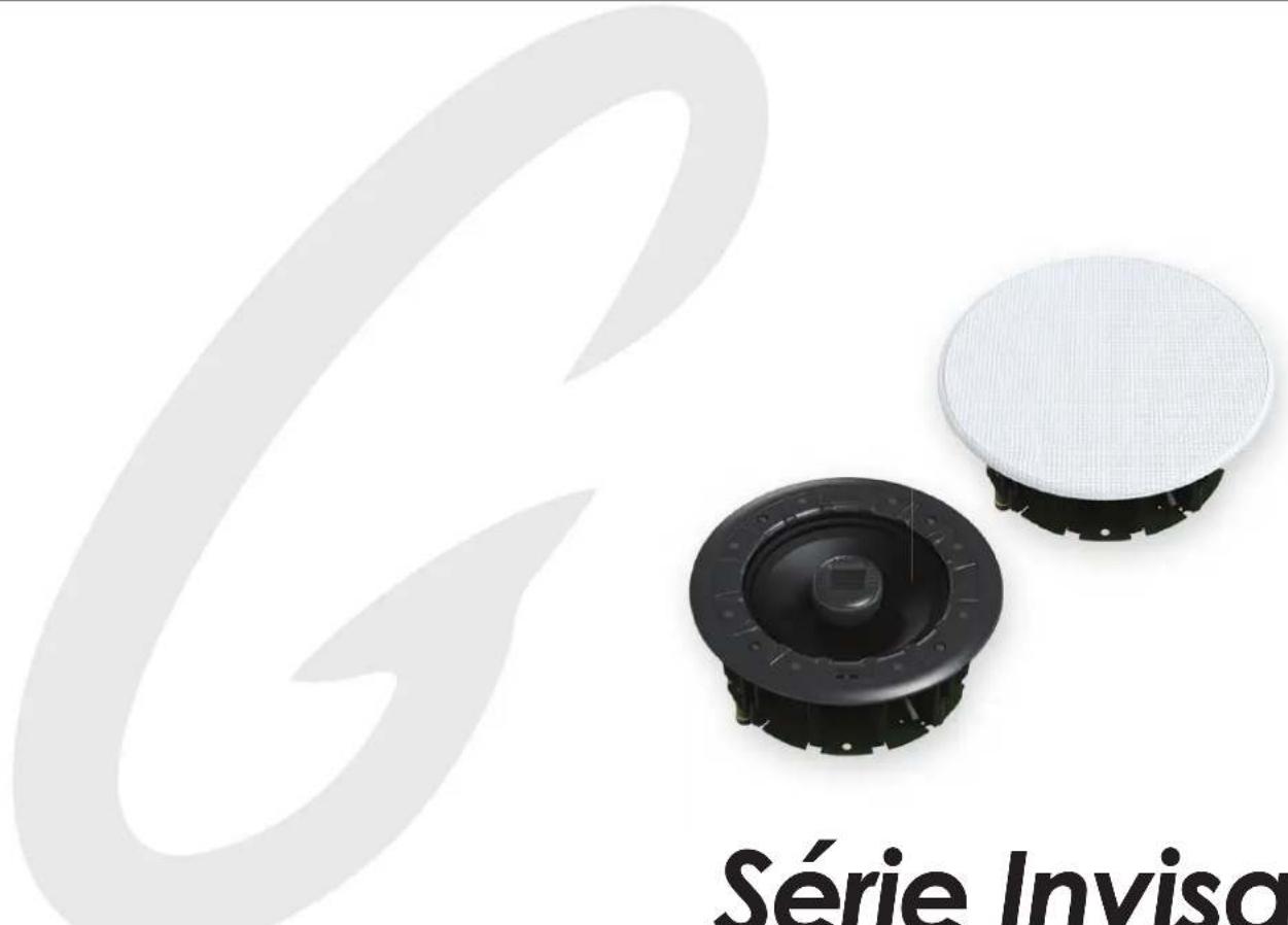
Exterior view of two Invisa Series speakers with a mesh cover, no text or symbols on the devices themselves.Invisa Series®
Invisa 525 • 650 • 850 In-Wall & In-Ceiling Loudspeakers
Owner's Manual
Congratulations
Congratulations and thank you for purchasing GoldenEar's ™ Invisa® speakers. You are about to hear the spectacular difference these very special In-Wall/In-Ceiling speakers will make in your home's music system.
Our engineers' many years of experience in developing loudspeakers has led to these extraordinary products. In order to ensure that you experience maximum performance, please take a moment to fully read this owner's manual and familiarize yourself with the unique installation, assembly and set-up procedures for your Invisa ^® speakers.
Please visit our website at www.GoldenEar.com for more information on the technology behind your new speaker system. If you have additional questions, contact your GoldenEar Authorized Dealer or visit the FAQs page in the Support section of our website.
Your New GoldenEar Speakers
GoldenEar Invisa® in-ceiling/in-wall speakers are designed to fit beautifully in a wide variety of applications. Their low-profile grille and nearly invisible design allows for perfect integration in a wide variety of locations within your home. To get the best performance possible and for a product that lasts a lifetime, we strongly recommend that you follow the placement and setup guidelines provided in this manual.
Cleaning
Do not use a strong or abrasive cleaner on your new speakers' grilles. Clean them only with a damp cloth, but do not get them wet.
Preventing Speaker Damage

USE AN APPROPRIATE AMPLIFIER. At high volumes a very powerful amplifier can overdrive your speakers and damage them. And if the amplifier is not powerful enough, it can produce distortion that can easily damage your speaker. (Consult your dealer for assistance.)

DON'T BE FOOLED BY THE VOLUME CONTROL. It only adjusts how loud, it is not an indication of power output. If your speakers begin to sound harsh or grating or if you hear other forms of distortion, turn down the volume immediately!

PROPER SETUP IS THE KEY. Please Note: Avoid use of tone controls and loudness controls as they will demand even more power from an amplifier.
GoldenEar Invisa® speakers are efficient and can be driven to loud listening levels with moderate amplifier power. They are also able to handle the output of very powerful amplifiers. To prevent damage to your speakers, please read all of the following guidelines before hooking them up.
Amplifier Distortion — #1 Threat to your New Speakers
Amplifier distortion is the principal cause of speaker damage. When listening at loud levels your amplifier may run out of clean power. It will then begin to produce speaker-damaging distorted power. This will damage any brand of speaker very quickly! More powerful amplifiers are actually safer — For example: A 40 Watt/channel amplifier will have substantial distortion above 40 Watts. If driven to 50 Watts, this amplifier will deliver speaker-damaging distorted power. But a 100 Watt/channel amplifier will have very low distortion below 100 Watts. Therefore, when the speaker requires 50 Watts, this more powerful amplifier will deliver clean power and speaker damage is less likely to occur. (See your GoldenEar dealer for amplifier recommendations.)
Volume Setting
Do not be fooled by the Volume setting of your system. It only adjusts listening level — it is not a "power-output" dial. The amount of amplifier power actually used at a given Volume setting depends solely on the nature of the source material you are listening to (at a given Volume setting a quiet section of music will use less amplifier power than a loud section). With typical material, the rated output power of many receivers/amplifiers is often reached when the Volume is set to around -10dB, or between the "11" and "1 o'clock" settings with an analog control (with bass/treble and loudness controls not used — otherwise rated power may be reached at even lower Volume settings). Remember, all amplifiers produce distortion when operated beyond their rated output power. The resulting distortion will damage all speakers. If you listen at loud levels, be careful to listen for the point of audible distortion — if the speakers begin to sound distressed, turn the Volume down or your speakers and/or amplifier(s) will be damaged! This type of damage constitutes abuse and is not covered by the warranty. If louder volumes are desired, consider a more powerful amplifier.
There is Actually a Limit
Even with these safer, more powerful amplifiers, there is a point at which you could have more power than the speaker can handle. At that point you will overpower the speaker and damage it. At loud levels do not increase bass/treble controls from zero and ensure that all loudness/contour/bass EQ buttons are off (otherwise rated output power will be reached at even lower volume control settings).
The Right Amount of Power
A power-range rating is given in the specifications as a guide to indicate the approximate minimum and maximum power input of your GoldenEar Invisa® speakers. Amplifiers that meet or even exceed the speaker's power-range rating are recommended as their greater power reserves provide better sound. But always use the speakers within their power-range rating to prevent damage — that is, keep listening levels below the point of obvious audible distortion.
Setting Bass and Treble Controls on Receiver or Amplifier
Normally we recommend that you set the "Bass" and "Treble" controls on flat (or off, or 0 dB). Same applies for a graphic equalizer; we recommend that you leave it flat (or off). This will give you the most accurate and natural sound. If you want more bass, raise your subwoofer's "Level" control (or raise the subwoofer level on you're a/v receiver), keeping in mind that even a little turn of the knob can make a big difference in the sound. The reason for this recommendation is that we have discovered what is often thought to be improper sounding speakers is, in fact, a problem caused by the use of tone controls. When in doubt, leave them out (flat); this almost always results in the best possible and most natural sounding system performance.
Speaker Placement
GoldenEar Invisa® speakers are designed to allow flexible placement while providing a very large window of sound throughout your listening room. Please remember that although the following recommendations are usually valid, all rooms and listening sets-ups are somewhat unique, so do not be afraid to experiment with the speakers. Remember, whatever sounds best to you is correct.
Room Acoustics
GoldenEar Invisa® speakers are designed to provide exceptional sound in a wide variety of domestic settings. It is important to note however that listening room construction, dimensions and furnishings all play a part in the quality of sound you will ultimately achieve from your new speakers. The listening room will impose its own character on the performance capabilities of the speaker system. Regarding the room, please note that:
- Mid and high frequencies are affected by the amount of soft furnishings in your room — curtains, carpets, sofas, wall coverings, etc. An excess of such items can result in a somewhat dull sound. The same room without any soft furnishings can produce an overall bright sound. The typical quantity of soft furnishings found in most living environments provides the right acoustic characteristics to allow the speakers to sound balanced;
- Concrete floors and walls tend to aggravate low-frequency standing wave problems and are less preferred;
- Rooms where height, width and length are similar should be avoided as they can exhibit significant low-frequency standing wave problems. This may result in reduced clarity. In such rooms avoid corner placement to minimize acoustic problems.
The extra care you take in correctly positioning the speakers will result in greater listening enjoyment. So, keep the following guidelines in mind when deciding on the best speaker placement.
To ensure the best performance possible, observe the following placement guidelines:
LOCATION: When preparing to install your speakers pick a location that has the required clearance between wall studs or ceiling joists. Make sure to check for wiring, conduit, water pipes, HVAC ducts and other obstructions before cutting the installation hole.
ACCURATE TIMBRE: For the most accurate and natural timbre, in-wall speakers' high-frequency drivers should be at approximately ear level. Select locations that allow the sound to reach the listening area unobstructed by furnishings.
BALANCED BASS: Placing speakers in corners will over-emphasize bass and reduce overall clarity. If possible, position speakers away from side walls. This will ensure better bass performance and optimal midrange clarity.
Positioning Invisa® In-Ceiling Speakers for Distributed Audio
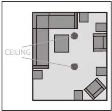
For In-Ceiling applications for "whole home" music playback, position speakers in stereo left/right pairs so they are approximately as far apart as the distance to the average listeners' positions. For very large spaces, you may wish to install additional stereo pairs of speakers approximately every twenty to twenty-five feet. (See figure to right).
Positioning Invisa ^® as Main Left/Center/Right Channel Speakers
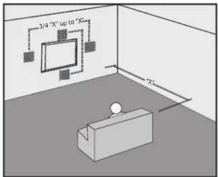
For In-Wall installations, for best imaging, measure the distance from your main listening area to the left front speaker (we'll call this distance "X"). For optimal imaging and largest soundstage, place speakers "X" distance apart from each other (and no less than 3/4 of that distance — 3/4 of "X" up to "X"). For Home Theater installations with L/C/R in-walls, place the center speaker above or below your TV, whichever position is closer to ear level, as shown in this figure:
Positioning Invisa® as Surrounds/Rears/Height Channel Speakers
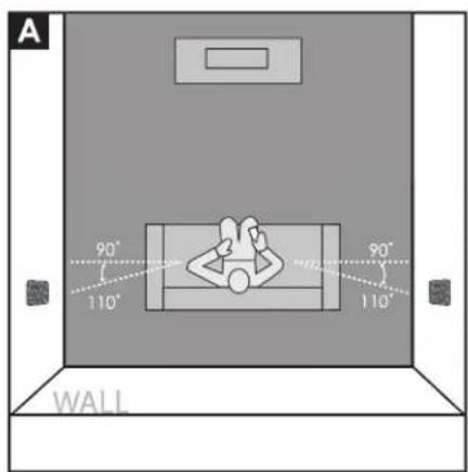
When used as surround speakers in a 5.1 system, Invisa ^® speakers may be located on the side, above, or behind the listeners. When used on the sides, take care never to locate the speakers forward of the listeners (Figure A).
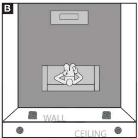
If the speakers are installed in the rear wall as surrounds, it is suggested that they be positioned fairly wide apart if possible. For instance, if there is a couch in the center of the rear wall on which the listeners will sit, try to position the speakers wider apart than the couch (See Figure B).
Surround and Rear In-Wall speakers should always be positioned at or near ear level if used in a system with Height channels. If not using Height channels, position Surround/Rear speakers as high as possible in the room.
In-Ceiling installations in the rear corners is also a good Surround speakers location (Figure B) for systems without Height channels.
Positioning Invisa • In-Wall as Surround Speakers
Rear Channel speakers in a 7.1 system should be placed about as far apart as the front main speakers, as shown (Figure C).
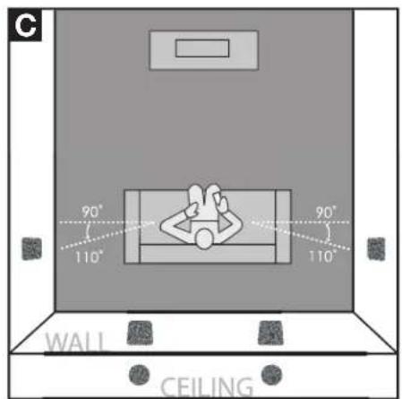
Positioning Invisa• In-Wall/Ceiling as Rear Speakers
In-Ceiling Height Channel speakers, shown in a 7.1.4 system configuration for example, should be placed about as far apart as the front main speakers, as shown (Figure D), just in front of and behind the main listening area.
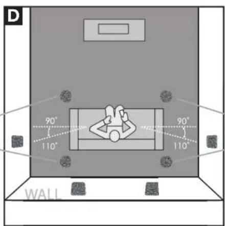
Positioning Invisa• In-Ceiling Height Speakers
Speaker Break-in
Your new Invisa® loudspeaker system should sound good as soon as you turn them on; however, an extended break-in period of 40-60 hours or more of normal playing time is required to reach full performance capability. Break-in allows the driver suspensions to work-in and crossover components to "heal," resulting in fuller and tighter bass, a more open "blossoming" midrange and smoother high-frequency reproduction.
Color-Match Painting (optional)
Your new Invisa in-wall/in-ceiling speakers include a paintable "edgeless" grille that completely covers the installed speaker. The grille comes in a neutral white to blend with most areas, however, for the ultimate in "stealth" installation, they may be painted to match any decor. PLEASE NOTE: Failure to follow the instructions below may result in a serious degradation of sound quality!
Please Note:
- Do not paint the grille with a brush or roller — this will clog the grille's acoustic perforations and muffle the sound.
- It is not necessary to remove the backing cloth, or scrim, from the grille before painting.
- Do not heat cure the finish.
- Do not paint the grilles while attached to the speaker.
To paint, follow these steps:
- Remove the grille from the speaker and place it on a drop cloth
- Spray paint the grille using:
i. A spray paint that closely matches the color and shine desired
ii. A custom-made spray can, color matched to your paint finish
iii. The indoor latex paint used to paint the ceiling or wall, but diluted to the paint manufacturer's/spray gun manufacturer's recommendations - In a well ventilated area, apply several light coats of paint, sprayed at about a 60 degree angle from the grille's surface, letting the grille dry completely between coats. Follow the paint manufacturer's directions.
- To insure the paint is evenly applied, each coat should be applied from multiple directions (at least four).
- Once the painted grille has dried completely, if necessary you can use a brush or small roller to touch-up the grille's outer edge — just be careful not to get any additional paint on the grille's perforated surface.
Installation Instructions
Installation of your new Invisa® speakers requires use of tools such as a drill, screwdriver, saws and possibly other power tools. The installer should have knowledge of all applicable building and/or fire codes. Care must be taken to ensure the area behind the wall or ceiling where you plan to install the speakers is clear of obstructions. When cutting the hole in and running wires through walls and/or ceilings proper care must be taken to avoid electrical, water, gas and/or HVAC pipes and the corresponding risks to your safety and risk of damage to property.
If you are not comfortable with the above and/or performing the following installation procedures we strongly suggest having a professional contractor install your speakers (see your GoldenEar Dealer).
Tools Required:
- Pencil
- Drywall saw, Keyhole saw, utility knife or other material-appropriate cutting tool for wall material
• Phillips Head Screwdriver
• Power drill with appropriate bit (optional, for starting wall cut)
Installation Into Existing Walls or Ceilings
For new construction (pre-drywall), use our custom rough-in brackets, sold separately.
NOTE: You must first install appropriate gauge and type speaker wires. For optimum sound, we strongly recommend using high-quality speaker cable.

Use only cable that is rated for in-wall use (UL Standard CL2, CL3 and CM, CSA standard FT4).
- Make sure the wall material can support the weight of the speakers you plan to install (see specifications page for weights).
- Make sure the location selected is free of studs, electrical wiring, water or gas pipes, etc. Prior to installing, hold the speaker in your selected location to make sure it is clear of any obstacles. PLEASE NOTE: Your cutout must be at least 2" (50mm) from adjoining walls/ceiling, internal studs, and any pipes.
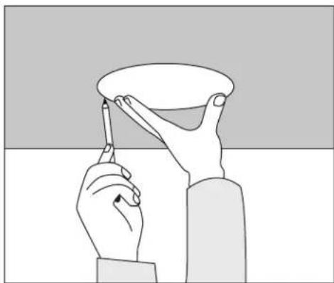
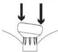
- Place the included mounting template onto the wall or ceiling in your preferred location. Use the pencil to trace around the template (Figure 1).
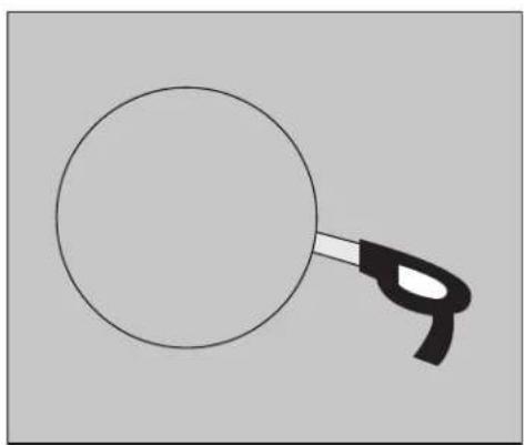
- Carefully cut a hole with the appropriate cutting tool along the pencil trace as follows: Start the hole by drilling a hole inside of the pencil line (place drill bit just inside the line). Use this hole to insert the cutting tool and begin cutting — be careful not to cut outside the template line! (Figure 2).
natural_image
Illustration of two hands holding a cup and a pen, with no text or symbols present.Figure 1
natural_image
Simple line drawing of a magnifying glass with handle (no text or symbols)Figure 2
5. For In-Wall Mounting:
- For optimum performance, loosely place two pieces of standard fiberglass insulation in the wall, one just above the hole and one just below. An 8" x 10" piece should work well, R-12 for a 2x4 wall, R-20 for a 2x6 wall.
- Also place a half-thick piece of fiberglass insulation cut to the height of the speaker in the wall right behind the mounting hole.
6. For In-Ceiling Mounting:
- For optimum performance, loosely place one piece of standard fiberglass insulation, cut to fit the joist size, above the speaker and extending about 15" or more beyond the speaker;
- For taller joists, also place fiberglass insulation against the joists on either side of the mounting hole.
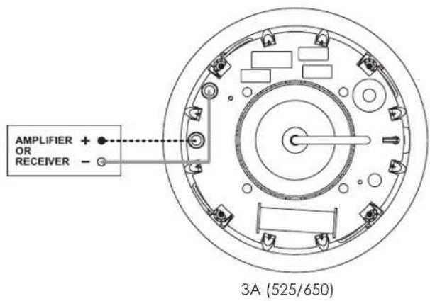
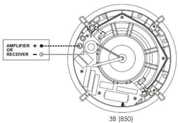
7. Pull the speaker wire out of the hole and connect the speaker as follows:
- Your Invisa ^ speakers are equipped with a set of four high-quality push spring connectors that can be used with bare wire. Make sure all wires are firmly fastened. Always use high quality speaker wire of the correct rating (see above) and sufficient gauge for the distances you are running (see your dealer for assistance).
- Strip 1/2'' (12 mm) of insulation from each of the two conductors to expose the metal, twist the strands of each into two single un-frayed strands. Repeat for the other channel's two conductors.
- Hold the speaker up to the cutout and connect the speaker cables. Proper polarity (or phase) is critical for proper stereo imaging and bass performance. Connect the red(+) terminal of your receiver or amplifier to the red(+) terminals of the Invisa loudspeaker and the black(-) terminal of your receiver or amplifier to the black(-) terminal of the Invisa loudspeaker. (See Figure 3). Most speaker cables are either color coded or have some indicator (ribbing or writing) on one of the conductors to help maintain this consistent polarity. It is essential that all speakers be connected in the same way (in phase) to its own channel of the amplifier. If you experience a great lack of bass, it is likely that one speaker is out of phase(+ and - reversed) with the other.
- Push down on the top of the speaker's push terminal to reveal the wire hole in the post. Insert the wire into the hole and release your pressure on the terminal. Repeat for all four connections.
Invisa 525 • 650 • 850 Owner's Manual
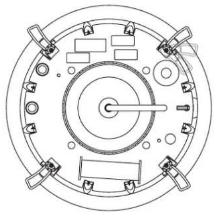
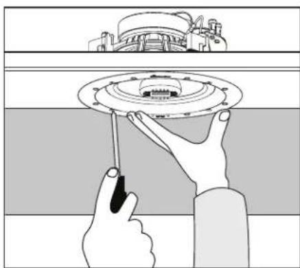
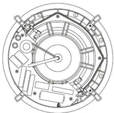
- Loosen the four rotating lock arms on the speaker by turning the arm screws on the front of the speaker counterclockwise 12 to 1 turn, just enough to allow the lock arm to move freely (Figure 4).
- Make sure the rotating lock arms are positioned inwards (Figure 5) so that your speaker fits into your cutout hole.
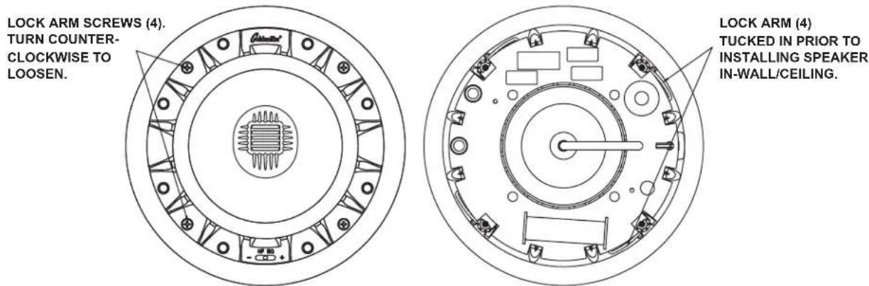
Figure 4A (525/650) Figure 5A (525/650)
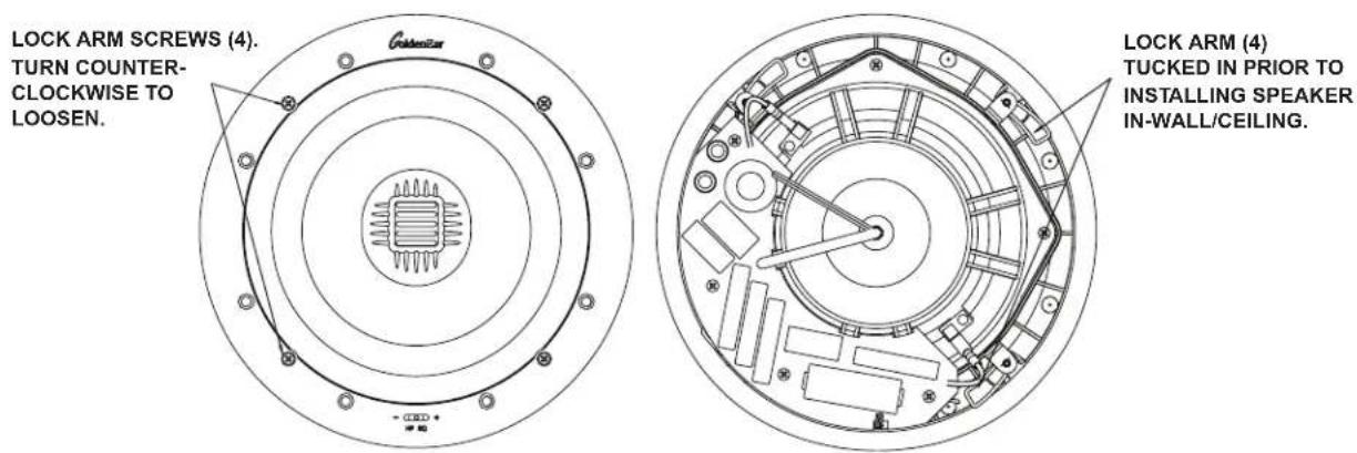
Figure 4B (850) Figure 5B (850)
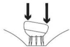
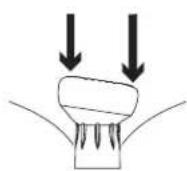
- Holding the speaker's front lip with your thumbs and index fingers, carefully slip the speaker into the cutout and hold firmly in place. (Figure 6).
natural_image
Illustration of hands installing or adjusting a circular mechanical component (no text or symbols visible)Figure 6A (525/650)

natural_image
Illustration of hands installing or adjusting a ceiling-mounted device component (no text or symbols visible)Figure 6B (850)
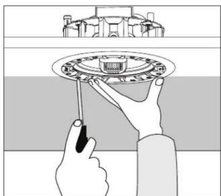
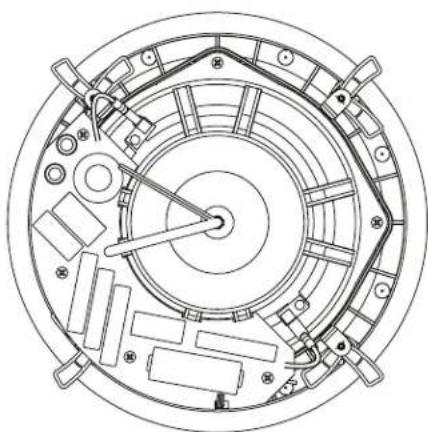
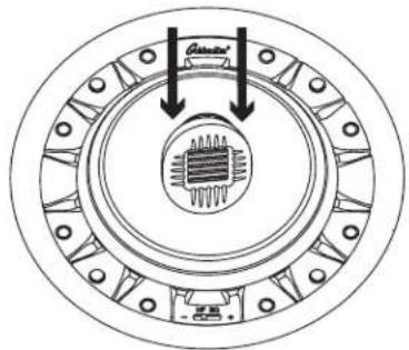
- While holding in place, tighten the four lock arm screws with a screwdriver (Figure 7). This will rotate the lock arms and secure the speaker to the wall/ceiling. DO NOT OVERTIGHTEN the lock arm screws as this could damage the drywall. If you are using a power screwdriver or drill, set the torque to a value of no more than 7 in.-lb (8dN-m).
TURN ARM SCREWS (4) CLOCKWISE TO TIGHTEN LOCK ARMS AND SECURE SPEAKER TO MOUNTING SURFACE.
natural_image
Top-down schematic of a circular mechanical or electrical component with multiple ports and central shaft (no text or symbols)Figure 7A (525/650)
TURN ARM SCREWS (4) CLOCKWISE TO TIGHTEN LOCK ARMS AND SECURE SPEAKER TO MOUNTING SURFACE.
natural_image
Technical line drawing of a circular mechanical assembly with internal components and mounting holes (no text or symbols)Figure 7B (850)
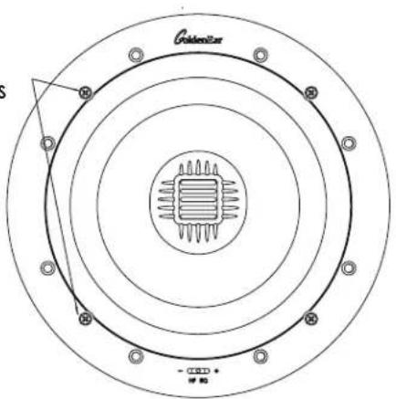
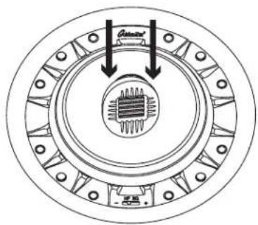
Setting the Invisa Speaker's High-Frequency EQ Control (HF EQ Switch)
We suggest starting with the HF EQ control (Figure 8) in the "+" position, in typical rooms with a balance of reflecting and absorbing surfaces. If, however, your listening room is overly "bright" due to many reflective, hard surfaces, select the center position to effectively compensate for this type of room acoustics issue. If the sound in the listening position is still too bright, select the "-" position to compensate further.
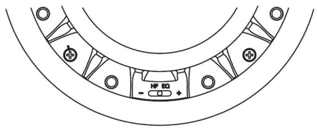
Figure 8A (525/650)
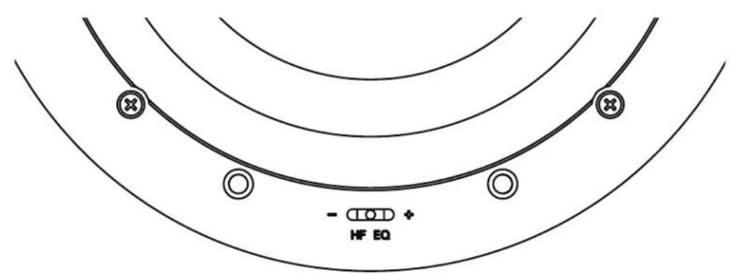
Figure 8B (850)
- Install the grille by placing it over the installed speaker and aligning the powerful miniature magnets.
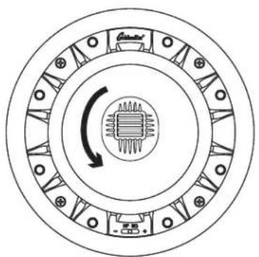
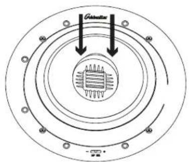
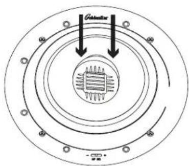
Adjusting the Pivoting Tweeter
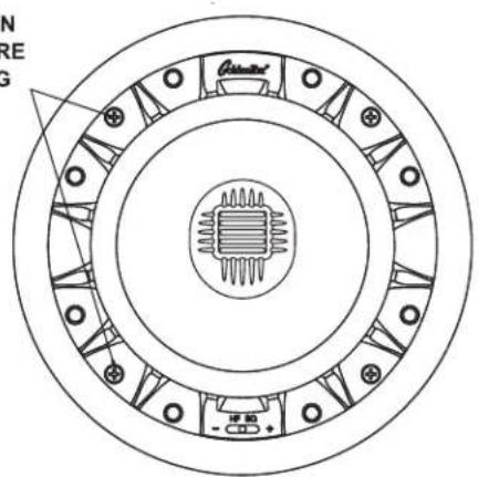
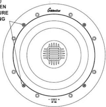
The Invisa® speakers incorporate an aim-able tweeter assembly to compensate for less than ideal placement situations, and to allow for an effective "toe-in" for In-Wall pairs. If your installation location is such that the primary listening area is well off axis from the speaker, the tweeter assembly can be rotated and tilted to allow it to be "aimed" at the listening area (See Figure 9). To aim the assembly for best results:
- With the speaker installed and the grille off, rotate the tweeter assembly so that the bars/slots are horizontal when viewed from the listening position;
- Again, while viewing from the listening position, tilt the tweeter assembly toward the listening position;
- For In-Wall applications, tilt the tweeter inward towards the center to create "toe-in."
natural_image
Circular diagram showing concentric rings with a central chip and directional arrow, no text or symbols present.AIM TWEETER IN DESIRED DIRECTION BY TURNING THE TWEETER ASSEMBLY
Figure 9A (525/650)
PUSH GENTLY IN DIRECTIONS OF HORIZONTAL SLOTS TO SET ANGLE
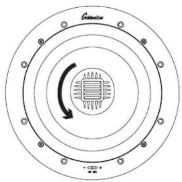
AIM TWEETER IN DESIRED DIRECTION BY TURNING THE TWEETER ASSEMBLY
Figure 9B (850)
PUSH GENTLY IN DIRECTIONS OF HORIZONTAL SLOTS TO SET ANGLE
Troubleshooting
If you experience any difficulties with your Invisa ^® speakers, try the suggestions described below. If you are still having problems, please consult your GoldenEar Authorized Dealer for assistance.
- Make sure all your system interconnects, speaker cables and power cords are solidly in place.
- Check that no foreign objects or liquid has entered the speaker.
- If no sound comes out or the sound is distorted in some way and you are sure the system is set up properly, please bring the speaker to your GoldenEar Authorized Dealer for assistance. But make sure you call first.
Service
Service and warranty work on your GoldenEar loudspeakers will normally be performed by your local GoldenEar dealer. If, however, you wish to return the speaker to us, please contact us first, describing the problem and requesting authorization as well as the location of the nearest factory service center. Please note that the address given in this booklet is the address of our office only. Under no circumstances should products or parts be shipped to our offices or returned without contacting us first and obtaining return authorization.
The Quest Group dba
GoldenEar™
2621 White Road
Irvine, CA 92614 USA
Phone: 949-800-1800
Technical assistance
It is our pleasure to offer assistance if you have any questions regarding your Invisa® speakers or their set-up. Please contact your nearest GoldenEar dealer or contact us directly at (949) 800-1800.
Recycling and Reuse Guidelines for Europe
In accordance with the European Union WEEE (Waste Electrical and Electronic Equipment) directive effective August 13, 2005, we would like to notify you that this product may contain regulated materials which, upon disposal, according to the WEEE directive, require special reuse and recycling processing. For this reason GoldenEar (manufacturers of GoldenEar speakers) has arranged with our distributors in European Union member nations to collect and recycle this product at no cost to you. To find your local distributor please contact the dealer from whom you purchased this product or go to our website at www.goldenear.com
Please note that the product only falls under the WEEE directive. When disposing of packaging and other shipping material we encourage you to recycle through the normal channels.
Specifications
Invisa® 525
Driver Complement: One Pivotable High-Velocity Folded Ribbon AMT Tweeter One 5.25" (13.33cm) High-Definition Cast-Basket Mid/Bass Driver
Efficiency: 90dB 1W/1M @ 4Ω (2.83V/1M)
Frequency Response: 45Hz–35kHz typical (-6dB on axis @ 100Hz, anechoic bass response)
Nominal Impedance: 4Ω
Recommended Amplification: 10–200Wpc
Dimensions: Speaker: 7.2" (18.2cm) diameter x 3.4" (8.6cm) D Cutout: 6.2" (15.7cm) diameter
Weight : Product: 3.5lbs (1.7kg); Shipping: 5lbs (2.3kg)
Invisa® 650
Driver Complement: One Pivotable High-Velocity Folded Ribbon AMT Tweeter One 6.5" (16.5cm) High-Definition Cast-Basket Mid/Bass Driver
Efficiency: 90dB 1W/1M @ 4Ω (2.83V/1M)
Frequency Response: 43Hz–35kHz typical (-6dB on axis @ 65Hz, anechoic bass response)
Nominal Impedance: 4Ω
Recommended Amplification: 10–250Wpc
Dimensions: Speaker: 8.1" (20.6cm) diameter x 3.4" (8.7cm) D Cutout: 7.1" (18cm) diameter
Weight : Product: 4lbs (1.8kg); Shipping: 5.5lbs (2.5kg)
Invisa® 850
Driver Complement: One Pivotable Reference High-Velocity Folded Ribbon AMT Tweeter One 8" (20.3cm) High-Definition Cast-Basket Multi-Vaned Phase Plug (MVPP) Mid/Bass Driver
Efficiency: 91dB 1W/1M @ 4Ω (2.83V/1M)
Frequency Response: 40Hz–35kHz typical (-6dB on axis @ 70Hz, anechoic bass response)
Nominal Impedance: 4Ω
Recommended Amplification: 10–300Wpc
Dimensions: 10" (25.4cm) diameter x 4.6" (11.8cm) D Cutout: 9" (22.9cm) diameter
Weight : 7lbs (3.1kg); Shipping: 8.5lbs (3.9kg)
Specifications are subject to change without notice.
GoldenEar™
Limited Warranty
5-YEARS FOR DRIVERS AND CABINETS, 3-YEARS FOR ELECTRONIC COMPONENTS
GoldenEar™ warrants to the original retail purchaser only that this GoldenEar Loudspeaker Product (the "Product") will be free from defects in materials and workmanship for a period of five (5) years covering the drivers and cabinets, and three (3) years for the electronic components from the date of the original purchase from a GoldenEar Authorized Dealer. However, this warranty will automatically terminate prior to the expiration of five (5) years for the drivers and cabinets and three (3) years for the electronic components if the original retail purchaser sells or otherwise transfers the Product to any other party. The original retail purchaser shall hereinafter be referred to as "you." Defective Products must be shipped, together with proof of date of purchase, prepaid insured to the Authorized Dealer from whom you purchased the Product, or to the nearest factory service center. Product(s) must be shipped in the original shipping container or its equivalent; in any case the risk of loss or damage in transit is to be borne by you. If, upon examination at the Factory or a GoldenEar Authorized Dealer, it is determined that the unit was defective in materials or workmanship at any time during this Warranty period, GoldenEar or the GoldenEar Authorized Dealer will, at its option, repair or replace this Product at no additional charge, except as set forth below. All replaced parts and Product(s) become the property of GoldenEar. Product(s) replaced or repaired under this Warranty will be returned to you, within a reasonable time, freight collect.
This Warranty does not include service or parts to repair damage caused by accident, misuse, abuse, negligence, inadequate packing or shipping procedures, commercial use, voltage in excess of the rated maximum of the unit, cosmetic appearance of cabinetry not directly attributable to defects in materials or workmanship, or service, or repair or modification of the Product which has not been authorized by GoldenEar. GoldenEar makes no Warranty with respect to its Products purchased from dealers or outlets other than GoldenEar Authorized Dealers. This Warranty is in lieu of all other expressed Warranties. If this Product is defective in material or workmanship as warranted above, your sole remedy shall be repair or replacement as provided above. In no event will GoldenEar be liable to you for any incidental or consequential damages arising out of the use or inability to use the Product, even if GoldenEar or a GoldenEar Authorized Dealer has been advised of the possibility of such damages, or for any claim by any other party. Some states do not allow the exclusion or limitation of consequential damages, so the above limitation may not apply to you.
All implied warranties on the Product are limited to the duration of this expressed Warranty. Some states do not allow limitation on how long an implied Warranty lasts, so the above limitations may not apply to you. This Warranty gives you specific legal rights, and you also may have other rights which vary from state to state.
C€
This product complies with the essential requirements of the EMC directive 89/336/EEC
Visit us at www.goldenear.com
Copyright © 2023 GoldenEar. All rights reserved.
Reproduction in whole or in part without our express permission is prohibited.
GoldenEar™
Série Invisa®
natural_image
Illustration of hands holding a pen over a document with a handle, no text or symbols presentFigure 1
natural_image
Simple line drawing of a tool interacting with a rectangular object (no text or symbols)Figure 2
5. Pour Montage Mural:
natural_image
Illustration of hands installing or adjusting a circular mechanical component (no text or symbols visible)Figure 6A (525/650)
natural_image
Illustration of hands installing or adjusting a ceiling-mounted device component (no text or symbols visible)Figure 6B (850)
natural_image
Circular mechanical component diagram with concentric rings and internal stator-like structure (no text or symbols)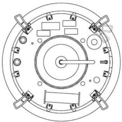
natural_image
Top-down schematic of a circular mechanical or electrical component with multiple ports and central shaft (no text or symbols)Figure 7A (525/650)
TOURNER LES VIS (4)
DU BRAS DANS LE SENS
HORAIRE POUR SERRER LES
BRAS DE VERROUILLAGE
ET SÉCURISER LEHAUT-
PARLEUR À LA SURFACE
DE MONTAGE
natural_image
Technical line drawing of a circular mechanical component with internal gears and mounting holes (no text or symbols)Figure 7B (850)
Figure 8A (525/650)
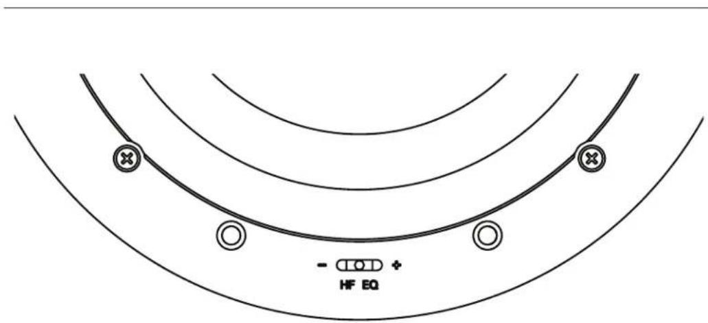
Figure 8B (850)
natural_image
Circular diagram showing a central component with internal circuit-like structure and directional arrows, no text or symbols present.POUSSEZ DOUCEMENT DANS LES DIRECTIONS DES FENTES HORIZONTALES POUR RÉGLER L'ANGLE
Figure 9A (525/650)

VISEZ LE TWEETER DANS LA DIRECTION SOUHAITÉE EN TOURNANT L'ASSEMBLAGE DU TWEETER

POUSSEZ DOUCEMENT DANS LES DIRECTIONS DES FENTES HORIZONTALES POUR RÉGLER L'ANGLE
Figure 9B (850)
VISEZ LE TWEETER DANS LA DIRECTION SOUHAITÉE EN TOURNANT L'ASSEMBLAGE DU TWEETER
Dépannage
Assistance technique
Visitez www.goldenear.com
- Invisa Series®
- Congratulations
- Your New GoldenEar Speakers
- Cleaning
- Preventing Speaker Damage
- Amplifier Distortion — #1 Threat to your New Speakers
- Volume Setting
- There is Actually a Limit
- The Right Amount of Power
- Setting Bass and Treble Controls on Receiver or Amplifier
- Speaker Placement
- Room Acoustics
- Positioning Invisa® In-Ceiling Speakers for Distributed Audio
- Positioning Invisa ® as Main Left/Center/Right Channel Speakers
- Positioning Invisa® as Surrounds/Rears/Height Channel Speakers
- Speaker Break-in
- Color-Match Painting (optional)
- Please Note:
- Installation Instructions
- Installation Into Existing Walls or Ceilings
- For In-Wall Mounting:
- For In-Ceiling Mounting:
- Pull the speaker wire out of the hole and connect the speaker as follows:
- Invisa 525 • 650 • 850 Owner's Manual
- Setting the Invisa Speaker's High-Frequency EQ Control (HF EQ Switch)
- Adjusting the Pivoting Tweeter
- Troubleshooting
- Service
- Technical assistance
- Recycling and Reuse Guidelines for Europe
- Specifications
- Invisa® 525
- Invisa® 650
- Invisa® 850
- GoldenEar™
- Limited Warranty
- 5-YEARS FOR DRIVERS AND CABINETS, 3-YEARS FOR ELECTRONIC COMPONENTS
- Visit us at www.goldenear.com
- Série Invisa®
- Pour Montage Mural:
- Dépannage
- Assistance technique
Brand : GoldenEar
Model : Invisa 850
Category : Speaker