
ARXC35BV1B - Air Conditioning DAIKIN - Free user manual and instructions
Find the device manual for free ARXC35BV1B DAIKIN in PDF.
Download the instructions for your Air Conditioning in PDF format for free! Find your manual ARXC35BV1B - DAIKIN and take your electronic device back in hand. On this page are published all the documents necessary for the use of your device. ARXC35BV1B by DAIKIN.
USER MANUAL ARXC35BV1B DAIKIN
MODEL NAME PLATE BOTTOM BOTTOM REAR REAR All dimensions are in mm All dimensions are in mmEnglish 1-3 OUTLINE DIMENSION
All dimensions are in mm
All dimensions are in mm1-4 OUTLINE DIMENSION
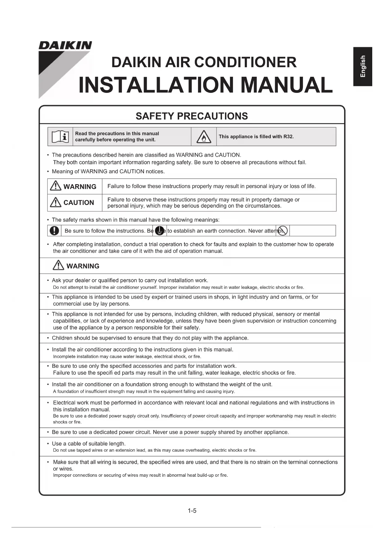
All dimensions are in mm1-5 English SAFETY PRECAUTIONS Read the precautions in this manualcarefully before operating the unit.This appliance is filled with R32.• The precautions described herein are classified as WARNING and CAUTION.They both contain important information regarding safety. Be sure to observe all precautions without fail.• Meaning of WARNING and CAUTION notices. WARNING Failure to follow these instructions properly may result in personal injury or loss of life. CAUTION Failure to observe these instructions properly may result in property damage orpersonal injury, which may be serious depending on the circumstances.• The safety marks shown in this manual have the following meanings:Be sure to follow the instructions. Be sure to establish an earth connection. Never attempt.
- After completing installation, conduct a trial operation to check for faults and explain to the customer how to operate the air conditioner and take care of it with the aid of operation manual. WARNING
- Ask your dealer or qualified person to carry out installation work. Do not attempt to install the air conditioner yourself. Improper installation may result in water leakage, electric shocks or fire.
- This appliance is intended to be used by expert or trained users in shops, in light industry and on farms, or for commercial use by lay persons.• This appliance is not intended for use by persons, including children, with reduced physical, sensory or mental capabilities, or lack of experience and knowledge, unless they have been given supervision or instruction concerning use of the appliance by a person responsible for their safety.• Children should be supervised to ensure that they do not play with the appliance.• Install the air conditioner according to the instructions given in this manual.Incomplete installation may cause water leakage, electrical shock, or fire.• Be sure to use only the specified accessories and parts for installation work. Failure to use the specifi ed parts may result in the unit falling, water leakage, electric shocks or fire.
- Install the air conditioner on a foundation strong enough to withstand the weight of the unit.A foundation of insufficient strength may result in the equipment falling and causing injury.
- Electrical work must be performed in accordance with relevant local and national regulations and with instructions in this installation manual. Be sure to use a dedicated power supply circuit only. Insufficiency of power circuit capacity and improper workmanship may result in electric shocks or fire.• Be sure to use a dedicated power circuit. Never use a power supply shared by another appliance.• Use a cable of suitable length. Do not use tapped wires or an extension lead, as this may cause overheating, electric shocks or fire.
- Make sure that all wiring is secured, the specified wires are used, and that there is no strain on the terminal connections or wires.Improper connections or securing of wires may result in abnormal heat build-up or fire.
DAIKIN AIR CONDITIONER
INSTALLATION MANUAL1-6
- When wiring the power supply and connecting the wiring between the indoor and outdoor units, position the wires so that the control box lid can be securely fastened. Improper positioning of the control box lid may result in electric shocks, fire or overheating terminals.
- After connecting interconnecting and supply wiring, be sure to shape the cables so that they do not put undue force on the electrical covers or panels. Install covers over the wires. Incomplete cover installation may cause terminal overheating, electrical shocks, or fire.
- When installing or relocating the air conditioner, be sure to bleed the refrigerant circuit to ensure it is free of air, and use only the specified refrigerant (R32). The presence of air or other foreign matter in the refrigerant circuit cause abnormal pressure rise, which may result in equipment damage and even injury.
- The installation height from the floor must be over 2.7m.
- If refrigerant gas leaks during installation, ventilate the area immediately. Toxic gas may be produced if the refrigerant comes into contact with fire.
- After completing installation, check for refrigerant gas leakage. Toxic gas may be produced if the refrigerant gas leaks into the room and comes into contact with a source of fire, such as a fan heater, stove or cooker.
- During pump-down, stop the compressor before removing the refrigerant piping. If the compressor is still running and the stop valve is open during pump-down, air will be sucked in when the refrigerant piping is removed, causing abnormal pressure in the refrigeration cycle, which may result in equipment damage and even injury.
- During installation, attach the refrigerant piping securely before running the compressor. If the refrigerant pipes are not attached and the stop valve is open when the compressor is run, air will be sucked in, causing abnormal pressure in the refrigeration cycle, which may result in equipment damage and even injury.
- Be sure to earth the air conditioner. Do not earth the unit to a utility pipe, lightning conductor or telephone earth lead. Imperfect earthing may result in electric shocks.
- Be sure to install an earth leakage breaker. Failure to install an earth leakage breaker may result in electrical shocks, or fire.
- All electrical wiring must not touch the water piping or any moving parts of the fan motors.
- Confirm that the unit has been switched OFF before installing or servicing the unit.
- Disconnect from the main power supply before servicing the air conditioner unit.
- DO NOT pull out the power cord when the power is ON. This may cause serious electrical shocks which may result in fire hazards.
- Keep the indoor and outdoor units, power cable and transmission wiring, at least 1m from TVs and radios, to prevent distorted pictures and static. Depending on the type and source of the electrical waves, static may be heard even when more than 1m away.
- Do not use means to accelerate the defrosting process (if applicable) or to clean, other than those recommended by the manufacturer.
- The appliance must be stored in a room without continuously operating ignition sources (for example: open flames, an operating gas appliance or an operating electric heater).
- Do not pierce or burn.
- Be aware that refrigerants may not contain an odour.
- The appliance must be installed, operated and stored in a room with a floor area larger than Xm2 (refer to Section “Special Precautions When Dealing With R32 Unit”). In case it does not satisfy minimum floor area, it requires to install at good ventilation room.
- NOTE: The manufacturer may provide other suitable examples or may provide additional information about the refrigerant odour.1-7 English CAUTION
- Do not install the air conditioner at any place where there is danger of flammable gas leakage. In the event of a gas leakage, build-up of gas near the air conditioner may cause a fire to break out.
- While following the instructions in this installation manual, install drain piping to ensure proper drainage and insulate piping to prevent condensation. Improper drain piping may result in indoor water leakage and property damage.
- Tighten the flare nut according to specified method such as with a torque wrench. If the flare nut is too tight, it may crack after prolonged use, causing refrigerant leakage.
- Do not overcharge the unit. This unit is factory pre-charged. Overcharge will cause over-current or damage to the compressor.
- Ensure that the unit’s panel is closed after service or installation. Unsecured panels will cause the unit to operate noisily.
- Sharp edges and coil surfaces are potential locations which may cause injury hazards. Avoid from being in contact with these places.
- Before turning off the power supply set the remote controller’s ON/OFF switch to the “OFF” position to prevent the nuisance tripping of the unit. If this is not done, the unit’s fans will start turning automatically when power resumes, posing a hazard to service personnel or the user.
- Make sure to provide for adequate measure in order prevent that the outdoor unit be used as a shelter by small animals. Small animal making contact with electrical parts can cause malfunctions, smoke or fire. Please instruct the customer to keep the area around the unit clean.
- The temperature of refrigerant circuit will be high, please keep the inter-unit wiring away from copper pipes that are not thermally insulated.
- Only qualified personnel can handle, fill, purge and dispose of the refrigerant. NOTICE Disposal requirements Your air conditioning product is marked with this symbol. This means that electrical and electronic products shall not be mixed with unsorted household waste. Do not try to dismantle the system yourself: the dismantling of the air conditioning system, treatment of the refrigerant, of oil and of other parts must be done by a qualified installer in accordance with relevant local and national legislation. Air conditioners must be treated at a specialized treatment facility for re-use, recycling and recovery. By ensuring this product is disposed of correctly, you will help to prevent potential negative consequences for the environment and human health. Please contact the installer or local authority for more information. Batteries must be removed from the remote controller and disposed of separately in accordance with relevant local and national legislation.1-8 IMPORTANT Important information regarding the refrigerant used This product contains fluorinated greenhouse gases. Do not vent gases into the atmosphere. Refrigerant type: R32 GWP (1) value: 675 (1) GWP = Global Warming Potential 1 Please fill in with indelible ink, A the factory refrigerant charge of the product, B the additional refrigerant amount charged in the field and A + B the total refrigerant charge on the refrigerant charge label supplied with the product. The filled out label must be adhered in the proximity of the product charging port (e.g. onto the inside of the service cover). Contains fluorinated greenhouse gases
GWP: 675 R32 a Factory refrigerant charge: see unit name plate b Additional refrigerant amount charged c Total refrigerant charge d Greenhouse gas emissions of the total refrigerant charge expressed as tonnes CO
-equivalent e GWP = Global warming potential NOTICE In Europe, the greenhouse gas emissions of the total refrigerant charge in the system (expressed as tonnes CO
-equivalent) is used to determine the maintenance intervals. Follow the applicable legislation. Formula to calculate the greenhouse gas emissions: GWP value of the refrigerant × Total refrigerant charge [in kg] / 1000 2 Fix the label on the inside of the outdoor unit. There is a dedicated place for it on the wiring diagram label.1-9 English ACCESSORIES
Remote controller holder
AAA dry-cell batteries
Wireless remote controller
Fixing screws for remote controller holder M3 × 16L
Titanium apatite photocatalytic air-purifying filter
*Only for heat pump models.
CHOOSING AN INSTALLATION SITE
- Before choosing the installation site, obtain user approval. Indoor Unit The indoor unit should be sited in a place where:
- The restrictions on installation specified in the indoor unit installation drawing are met.
- Both air intake and exhaust have clear paths met.
- The unit is not in the path of direct sunlight.
- The unit is away from the sources of heat or steam.
- There is no source of machine oil vapour (this may shorten indoor unit life).
- Cool air is circulated through out the room.
- The unit is away from electronic ignition type flourescent lamps (inverter or rapid start type). As these may shorten the remote controller range.
- The unit is at least 1 metre away from any television or radioset (unit may cause interference with the picture or sound).
- Install at the recommended height (more than 2.7m).
- Do not install the units at or near doorway.
- Do not operate any heating apparatus too close to the air conditioner unit or use in room where mineral oil, oil vapour or oil steam exist, this may cause plastic part to melt or deform as a result of excessive heat or chemical reaction.
- When the unit is used in kitchen, keep flour away from going into suction of the unit.
- This unit is not suitable for factory used where cutting oil, mist or iron powder exist or voltage fluctuates greatly.
- Do not install the units at area like hot spring or oil refinery plant where sulphide gas exists.
- Ensure the color of wires of the outdoor unit and the terminal markings are same to the indoors respectively.
- IMPORTANT : DO NOT INSTALL OR USE THE AIR CONDITIONER UNIT IN A LAUNDRY ROOM. Do not use joined and twisted wires for incoming power supply. The equipment is not intended for use in a potentially explosive atmosphere. Wireless Remote Controller
- Do not expose the remote controller to direct sunlight (this will hinder receiving signals from the indoor unit).
- Turn on all the fluorescent lamps in the room, if any, and find the site where remote controller signals are properly received by the indoor unit (within 7 metres).1-10 Outdoor Unit The outdoor unit should be sited in a place where:
- The restrictions on installation specified in the outdoor unit installation drawing are met.
- Drain water causes no trouble or problem in particular.
- Both air intake and exhaust have clear paths of air.
- The unit is in a clear path of air but not directly exposed to rain, strong winds, or direct sunlight.
- There is no fear of inflammable gas leakage.
- The unit is no directly exposed to salt, sulfidized gases, or machine oil vapour (they may shorten outdoor unit life).
- Operation noise or hot (cold) air flow does not cause trouble to neighbours.
- The unit is at least 3 metres away from any television or radio antenna.
- Condensation dripping from the stop valve cannot damage anything during operation. CAUTION When operating the air conditioner in a low outdoor ambient temperature, be sure to follow the instructions described below.
- To prevent exposure to wind, install the outdoor unit with its suction side facing the wall.
- Never install the outdoor unit at a site where the suction side may be exposed directly to wind.
- To prevent exposure to wind, it is recommended to install a baffle plate on the air discharge side of the outdoor unit.
- Construct a large canopy.
- Construct a pedestal. Install the unit high enough off the ground to prevent burying in snow In heavy snow areas, select an installation site where the snow will not affect the unit.
- If there is a likelihood of snow accumulating on the outdoor unit, attach a snow protection hood.
- In high humidity areas or heavy snow areas, it is recommended to attach a drain pan heater to prevent ice build-up from the bottom frame. CAUTION Do not install the unit at altitude over 2000m for both indoor and outdoor.1-11 English
INDOOR/OUTDOOR UNIT INSTALLATION DRAWINGS
500mm from wall The service lid is removable Opening method
1) Remove the service
diagonally down in the direction of the arrow.
Service lid 55mm or more from ceiling Caulk pipe hole gap with putty. The flare connection should be installed outdoors Cut thermal insulation pipe to an appropriate length and wrap it with tape, making sure that no gap is left in the insulation pipe’s cut line. Wrap the insulation pipe with the finishing tape from bottom to top. Refrigerant piping must be protected from physical damage. Install a plastic cover or equivalent. CAUTION Set the piping length from 3m to 30m Allow space for piping and electrical servicing. Where there is a danger of the unit falling, use foot bolts. Allow 300mm of work space below the ceiling surface. Air filters Front panel Air filterFilter frame Tab Titanium apatite deodorizing filterTitanium apatite deodorizing filter (2) Screws (M4 x 12L) 50mm or more from walls (on both sides) How to remove the stop valve cover.
- Remove the screw on the stop valve cover.
- Slide the lid downward to remove it. How to attach the stop valve cover.
- Insert the upper part of the stop valve cover into the outdoor unit to install.
- Tighten the screws. Stop valve cover ARXC20/25/35 ARXC50/60/71 Max. allowable piping length 20m 30m Min. allowable piping length** 3m Max. allowable piping height 15m 20m Additional refrigerant required for refrigerant pipe exceeding 7.5m in length* 17g/m Gas pipe 3/8 inch (9.52mm) 1/2 inch (12.7mm) Liquid pipe 1/4 inch (6.4mm)
Be sure to add the proper amount of additional refrigerant. Failure to do so may result in reduced performance. ** The suggested shortest pipe length is 10ft (3m), in order to avoid noise from the outdoor unit and vibration. (Mechanical noise and vibration may occur depending on how the unit is installed and the environment in which it is used.)1-12
INSTALLING THE MOUNTING PLATE
- The mounting plate should be installed on a wall which can support the weight of the indoor unit. 1) Temporarily secure the mounting plate to the wall, make sure that the panel is completely level, and mark the drilling points on the wall.
2) Secure the mounting plate to the wall with screws.
Recommended mounting plate retention spots and dimensions Mounting plate fixing screwThe mounting plate should be installed on a wall which can support the weight of the indoor unit. Mounting plate
INDOOR UNIT ATXC20/25/35/50
Ø 65 Ø 65 Recommended mounting plateretention spots (7 spots in all)Place a leveleron these tabs.Use a tape measure asshown.Position the end of the tape measure atThrough-the-wall hole Ø 65mmDrain hose positionunit : mmAll dimensions are in mm
Ø 65 Recommended mounting plateretention spots (7 spots in all)Place a leveleron these tabs.Use a tape measure asshown.Position the end of thetape measure at Through-the-wall hole Ø 65mmDrain hose positionunit : mmAll dimensions are in mm1-13 English
- For walls containing metal frame or metal board, be sure to use a wall embedded pipe and wall cover in the feed-through hole to prevent possible heat, electrical shock, or fire.
- Be sure to caulk the gaps around the pipes with caulking material to prevent water leakage.
1) Drill a feed-through hole of 65mm in the wall so it has
a down slope toward the outside.
2) Insert a wall pipe into the hole.
3) Insert a wall cover into wall pipe.
4) After completing refrigerant piping, wiring, and drain
piping, caulk pipe hole gap with putty. Wall embedded pipe (Field supply)Caulking (Putty) (Field supply)InsideOutsideWall embedded pipe (Field supply) Ø 65 Wall hole cover (Field supply)
Right-side, right-back, or right-bottom piping.
1) Attach the drain hose to the underside of the refrigerant
pipes with adhesive vinyl tape.
2) Wrap the refrigerant pipes and drain hose together with
3) Pass the drain hose and refrigerant pipes through the wall
hole, then set the indoor unit on the mounting plate hooks by using the markings at the top of the indoor unit as a guide.
4) Open the front panel, then open the service lid. (Refer to installation tips.)
5) Pass the inter-unit wire from the outdoor unit through the
feed-through wall hole and then through the back of the indoor unit. Pull them through the front side. Bend the ends of tie wires upward for easier work in advance. (If the inter-unit wire ends are to be stripped first, bundle wire ends with adhesive tape.)
6) Press the bottom frame of the indoor unit with both hands to
set it on the mounting plate hooks. Make sure the wires do not catch on the edge of the indoor unit. Right-back piping Mounting plate Mounting plateHang indoor unit’s hook here.Inter-unit wire Wire guideWhen stripping the ends of inter-unit wire in advance, bundle ends of wires with insulation tape.Right-side pipingRight-bottom pipingBind refrigerant pipe and drain hose together with insulation tape.Remove pipe port cover here for right-bottom pipingRemove pipe port cover here for right-side piping1-14 Left-side, left-back, or left-bottom piping. How to replace the drain plug and drain hose
1) Rotate to detach wire clip from hook on the right
and remove the drain hose.
2) Remove the drain plug on the left side and attach it
3) Insert the drain hose and tighten by rotating the
wire clip to hook. Forgetting to tighten this may cause water leakages. Drain hose attachment position The drain hose is on the back of the unit. Wire clipLeft side Right sideFront side of unitAttachment on the left sideAttachment on the right side(factory default)Drain hose Drain hoseWire clip
1) Attach the drain hose to the underside of the refrigerant
pipes with adhesive vinyl tape.
2) Be sure to connect the drain hose to the drain port in place
3) Shape the refrigerant pipe along the pipe path marking on
4) Pass drain hose and refrigerant pipes through the wall hole,
then set the indoor unit on mounting plate hooks, using the markings at the top of indoor unit as a guide.
5) Pull in the inter-unit wiring.
6) Connect the inter-unit piping.
7) Wrap the refrigerant pipes and drain hose together with
insulation tape as right figure.
8) While take extra care while going through activities so that
the interconnecting wires do not damaged by indoor unit, press the bottom edge of indoor unit with both hands until it is firmly caught by the mounting plate hooks. Secure indoor unit to the mounting plate with the screws (M4 × 12L) . Wall embedded piping. Follow the instructions given Left-side, left-back, or left-bottom piping
1) Insert the drain hose to this depth so it won’t be pulled
out of the drain pipe. Drain hose Caulk this hole with putty or caulking material. Bind with plastic tape. Mounting plate Wrap insulating tape around the bent portion of refrigerant pipe. Overlap at least half the width of the tape with each turn. Do not apply lubricating oil (refrigerant machine oil) when inserting. Application of causes deterioration and drain leakage of the plug. Left-side piping Remove pipe port cover here for left- side piping. Remove pipe port cover here for left-bottom piping. Left-back piping Left-bottom piping ● How to set drain plug Insert a hexagon wrench (4mm) No gap Drain hose Drain hose Outer wall 50 mm or more Vinyl chloride drain pipe (VP-30) Inner wall Insert drain hose to this depth so it won’t be pulled out of drain pipe. Refrigerant pipes M4 × 12L (2 point) Mounting plate Bottom frame1-15 English The indoor unit must be installed in such a way so as to prevent short circuit of the cool discharged air with the hot return air. Please follow the installation clearance shown in the figure. Do not place the indoor unit where there could be direct sunlight shining on it. Also, this location must be suitable for piping and drainage, and be away from doors or windows. Return Air Required space min. 50 min. 50 min. 55 (Space for maintenance) (Space for maintenance) (Space for performance) Air flow (Indoor) All dimensions are in mm How to attach the indoor unit Hook the claws of the bottom frame to the
mounting plate. How to remove the indoor unit. Push up the marked area (at the lower part of the front grille) to release the claws. Mounting plate Claw Mark (rear side) Bottom frame Front grille
- Connect the drain hose, as described below. The drain hose should be inclined downward. No trap is permitted. Do not put the end of the hose in water.
- Water Drainage Water leaking Water leaking Water leaking Water retention Drain WrongWrongWrongCorrect End dipped into water
- Remove the air filters and pour some water into the drain pan to check the water flows smoothly.
- When drain hose requires extension, obtain an extension hose commercially available. Be sure to thermally insulate the indoor section of the extension hose. Indoor unit drain hose φ16 Extension drain hose Heat insulation tube (Field supply)
- When connecting a rigid polyvinyl chloride pipe (nominal diameter 16mm) directly to the drain hose attached to the indoor unit as with embedded piping work, use any commercially available drain socket (nominal diameter 16mm) as a joint. φ16 Drain hose supplied with the indoor unit socket (nominal diameter 16mm) polyvinyl pipe (diameter 16mm)1-16
WIRING IMPORTANT: * The figures shown in the table are for information purpose only. They should be checked and selected to comply with the local/national codes of regulations. This is also subject to the type of installation and conductors used. ** The appropriate voltage range should be checked with label data on the unit.
Indoor Unit Terminal BlockInterconnection cableOutdoor UnitTerminal BlockPower Supply CableFuse/CircuitBreakerMain SwitchPower Supply N/L2 L/L1 There must be an all poledisconnection in the supplymains with a contactseparation of at least 3mm.Model Indoor (ATXC) 20/25/35B 50/60/71BOutdoor (ARXC) 20/25/35B 50/60/71BVoltage range**220-240V/~/50Hz + Power supply cable size* Number of conductors
Recommended fuse/circuit breaker rating
- All wires must be firmly connected.
- Make sure all the wire do not touch the refrigerant piping, compressor or any moving parts.
- The connecting wire between the indoor unit and the outdoor unit must be clamped by using provided cord anchorage.
- The power supply cord must be equivalent to H07RN-F which is the minimum requirement.
- Make sure no external pressure is applied to the terminal connectors and wires.
- Make sure all the covers are properly fixed to avoid any gap.
- Use round crimp-style terminal for connecting wires to the power supply terminal block. Connect the wires by matching to the indication on terminal block. (Refer to the wiring diagram attached on the unit). Attach insulation sleeveRound crimp-style terminalElectric wire
- Use the correct screwdriver for terminal screws tightening. Unsuitable screwdrivers can damage the screw head.
- Over tightening can damage the terminal screws.
- Do not connect wire of different gauge to same terminal.
- Keep wiring in an orderly manner. Prevent the wiring from obstructing other parts and the terminal box cover. Connect wires of the same gauge to both side.Do not connect wires of thesame gauge to one side.Do not connect wiresof different gauges.1-17 English
- Where a wall or other obstacle is in the path of outdoor unit’s intake or exhaust airflow, follow the installation guidelines below.
- For any of the below installation patterns, the wall height on the exhaust side should be 1200mm or less.
DRAIN WORK Drain work. (Heat Pump Unit Only)
1) Use drain socket for drainage.
2) If the drain port is covered by a mounting base or floor surface, place
additional foot bases of at least 30mm (1-3/16”) in height under the outdoor unit’s feet.
3) In cold areas, do not use a drain hose with the outdoor unit.
(Otherwise, drain water may freeze, impairing heating performance.)
Wall facing one side Wall facing one side Walls facing two sides Walls facing two sides Walls facing three sides Walls facing three sides More than 50More than 100More than 50More than 50More than 50More than 50More than More than More than 100More than 350More than 100More than 100More than More than More than 150More than 100More than 300More than 350Side viewSide viewTop viewTop viewTop viewTop view1200 or less1200 or less ARXC20/25/35 ARXC50/60/71 Drain water holeBottom frameDrain socketHose (available commercially,inner dia. 5/8"(16mm))
1) Cut the pipe end with a pipe cutter.
2) Remove burrs with the cut surface facing downward so that
the chips do not enter the pipe.
3) Put the flare nut on the pipe.
5) Check that the flaring is properly made.
FLARING THE PIPE END
(Cut exactly at right angles.) Flaring Set exactly at the position shown below. Remove burrs. Die A1-18
- Do not use mineral oil on flared part.• Prevent mineral oil from getting into the system as this would reduce the lifetime of the units.• Never use piping which has been used for previous installations.• Only use parts which are delivered with the unit.• Do never install a drier to this R32 unit in order to guarantee its lifetime.• The drying material may dissolve and damage the system.• Incomplete flaring may cause refrigerant gas leakage. WARNING Do not reuse joints which have been used once already. CAUTION
1) Use the flare nut fixed to the main unit. (To prevent cracking of the flare nut by aged deterioration.)
2) To prevent gas leakage, apply refrigeration oil only to the inner surface of the flare. (Use refrigeration oil for R32.)
3) Use torque wrenches when tightening the flare nuts to prevent damage to the flare nuts and gas leakage.
CAUTION Align the centres of both flares and tighten the flare nuts 3 or 4 turns by hand. Then tighten them fully with the torque wrenches.1. Cautions on pipe handling1) Protect the open end of the pipe against dust and moisture.2) All pipe bends should be as gentle as possible.Use a pipe bender for bending.2. Selection of copper and heat insulation materialsWhen using commercial copper pipes and fittings, observe the following:1) Insulation material: Polyethylene foamHeat transfer rate: 0.041 to 0.052W/mK (0.035 to 0.045kcal/(mh •˚C)Refrigerant gas pipe’s surface temperature reaches 110˚C max.Choose heat insulation materials that will withstand this temperature.2) Be sure to insulate both the gas and liquid piping and to provide insulation dimensions as below.Gas side Liquid side Gas pipe thermal insulation Liquid pipe thermal insulationO.D. 12.7mm O.D. 6.4mm I.D. 14-16mm I.D. 8-10mmMinimum bend radius Thickness 10mm Min.40mm or more 30mm or moreThickness 0.8mm(C1220T-O)3) Use separate thermal insulation pipes for gas and liquid refrigerant pipes.Ø Tube, D A (mm) Inch mm Imperial(Wing-nut Type)Rigid(Clutch Type)1/4" 6.40 1.3 0.73/8" 9.52 1.6 1.01/2" 12.70 1.9 1.35/8" 15.882.2 1.73/4" 19.052.5 2.0Flare’s inner surface must be flaw-freeThe pipe end must be evenly flared in a perfect circle.Make sure that the flare nut is fitted.Check[Apply oil]Apply refrigeration oil to the inner surface of the flare.Do not apply refrigerationoil to the outer surface.Do not apply refrigeration oil to the flare nut to avoid tightening with excessive torque.Flare nut[Tighten]Torque wrenchSpannerPipe unionFlare nut Wall Rain Be sure to place a cap.If no flare cap is available, co ver the flare mouth with tape to keep dirt or water out.Pipe Size, mm (in) Torque, Nm/(ft-lb)6.40 (1/4") 18 (13.3)9.52 (3/8") 42 (31.0)12.70 (1/2") 55 (40.6)15.88 (5/8") 65 (48.0)19.05 (3/4") 78 (57.6)Inter-unit wireDrain hoseLiquid pipe insulationGas pipe insulationFinishing tapeGas pipeLiquid pipe1-19 English
- When piping work is completed, it is necessary to purge the air and check for gas leakage
1) Do not mix any substance other than the specified refrigerant (R32) into the refrigeration cycle.
2) When refrigerant gas leaks occur, ventilate the room as soon and as much as possible.3) R32, as well as other refrigerants, should always be recovered and never be released directly into the environment. 4) Use a vacuum pump for R32 exclusively. Using the same vacuum pump for different refrigerants may damage the vacuum pump or the unit. WARNING
- If using additional refrigerant, perform air purging from the refrigerant pipes and indoor unit using a vacuum pump, then charge additional refrigerant.
- Use a hexagonal wrench (4mm) to operate the stop valve rod.
- All refrigerant pipe joints should be tightened with a torque wrench at the specified tightening torque. Pressure meterValve caps Liquid stop valveGas stop valveVacuum pump Service portHigh pressure valveLow-pressure valveCharging hosesCompound pressure gaugeGauge manifold
1) Connect projection side of charging hose (which comes from gauge manifold) to gas stop valve’s service port.
2) Fully open gauge manifold’s low-pressure valve (Lo) and completely close its high-pressure valve (Hi).
(High-pressure valve subsequently requires no operation.)
3) Do vacuum pumping and make sure that the compound pressure gauge reads - 0.1MPa ( - 760mmHg)*
4) Close gauge manifold’s low-pressure valve (Lo) and stop vacuum pump. (Keep this state for a few minutes to
make sure that the compound pressure gauge pointer does not swing back.)*
5) Remove covers from liquid stop valve and gas stop valve.
6) Turn the liquid stop valve’s rod 90 degrees counterclockwise with a hexagonal wrench to open valve.
Close it after 5 seconds, and check for gas leakage. Using soapy water, check for gas leakage from indoor unit’s flare and outdoor unit’s flare and valve rods. After the check is complete, wipe all soapy water off.
7) Disconnect charging hose from gas stop valve’s service port, then fully open liquid and gas stop valves.
(Do not attempt to turn valve rod beyond its stop.) 8) Tighten valve caps and service port caps for the liquid and gas stop valves with a torque wrench at the specified torques. *1. Pipe length vs. vacuum pump run time Pipe length Up to 15 metres More than 15 metresRun time Not less than 10 min. Not less than 15 min. *2. If the compound pressure gauge pointer swings back, refrigerant may have water content or a loose pipe joint may exists. Check all pipe joints and retighten nuts as needed, then repeat steps 2) through 4).
In order to protect the environment, be sure to pump down when relocating or disposing of the unit.1) Remove the valve lids from liquid stop valve and gas stop valve.2) Carry out forced cooling operation.
3) After five to ten minutes, close the liquid stop valve with a hexagonal wrench.
4) After two to three minutes, close the gas stop valve and stop forced cooling
- Do not use tapped wires, extension cords, or starburst connections, as they may cause overheating, electric shock, or fire.• Do not use locally purchased electrical parts inside the product. (Do not branch the power for the drain pump, etc., from the terminal block.) Doing so may cause electric shock or fire.• Be sure to install a earth leakage circuit breaker. (One that can handle higher harmonics.)(This unit uses an inverter. Therefore, a earth leakage circuit breaker capable of handling higher harmonics must be used in order to prevent the earth leakage circuit breaker malfunctioning.)• Use an all-pole disconnection type circuit breaker with at least 3mm (1/8 inch) between the contact point gaps.• When carrying out wiring, take care not to pull at the conduit.• Do not connect the power wire to the indoor unit. Doing so may cause electric shock or fire.• Do not turn on the circuit breaker until all work is completed.1) Strip the insulation from the wire (20mm).2) Connect the inter-unit wires between the indoor and outdoor units so that the terminal numbers match. Tighten the terminal screws securely. It is recommended that a flathead screwdriver be used to tighten the screws. The screws are packed with the terminal block.
Firmly fix the wires with the terminal screws. Power supply wire 3-core 2.5mm
or more 60245 IEC 57 H05RN Firmly fix the wires with the terminal screws. Earth Power supply terminal block
Shape wires so that the service lid and stop valve cover fit securely. Forced cooling operation Using the indoor unit ON/OFF switch Press the indoor unit ON/OFF switch for at least 5 seconds. (The operation will start.)
- Forced cooling operation will stop automatically after around 15 minutes. To stop the operation, press the indoor unit ON/OFF switch. After closing the liquid stop valve, close the gas stop valve within 3 minutes, then stop the forced cooling operation.
Pump down - Refrigerant leakage. If you want to pump down the system, and there is a leakage in the refrigerant circuit:
- Do NOT use the unit's automatic pump down function, with which you can collect all refrigerant from the system into the outdoor unit. Possible consequence: Self-combustion and explosion of the compressor because of air going into the operating compressor.
- Use a separate recovery system so that the unit's compressor does NOT have to operate. NOTICE During pump down operation, stop the compressor before removing the refrigerant piping. If the compressor is still running and the stop valve is open during pump down, air will be sucked into the system. Compressor breakdown or damage to the system can result due to abnormal pressure in the refrigerant cycle.1-21 English SPECIAL PRECAUTIONS WHEN DEALING WITH R32 UNIT ModelR32 charge, kgfor 7.5m pipingMinimum floor area,
(based on 7.5mpiping)R32 charge, kg for max allowable pipe length*Minimum floor area, Xm (based on max allowablepipe length*)ATXC20B - ARXC20B 0.55 0.29 0.76 0.55ATXC25B - ARXC25B 0.55 0.29 0.76 0.55ATXC35B - ARXC35B 0.75 0.54 0.96 0.88ATXC50B - ARXC50B 1.00 0.95 1.38 1.82ATXC60B - ARXC60B 1.10 1.15 1.48 2.10ATXC71B - ARXC71B 1.15 1.26 1.53 2.24* Calculation based on Installation Height of 1.8m* Max. Allowable Length (L),m for:-ATXC20/25/35B-ARXC20/25/35B:20ATXC50/60/71B-ARXC50/60/71B:30• Installation of pipe work shall be kept to a minimum and pipe work shall be protected from physical damage and shall not be installed in an unventilated space.• Reusable mechanical connectors and flare joints shall be accessible for maintenance purposes. WARNING Prior to installation, ensure risk of ignition is minimised and avoid working in confined space. Ensure adequate ventilation is available by opening windows or doors. ● When flared joints are reused indoors, the flare part shall be re-fabricated. ● A void installation of the air conditioner in a place where there is danger of exposure to continuously operating open flames (for example an operating electric heaters). ● Any person who is involved with working on or breaking into a refrigerant circuit should hold a current valid certificate from an industry-accredited assessment authority, which authorises their competence to handle refrigerants safely in accordance with an industry recognised assessment specification. ● Checking for presence of refrigerant The area shall be checked with an appropriate refrigerant detector prior to and during work, to ensure the technician is aware of potentially flammable atmospheres. Ensure that the leak detection equipment being used is suitable for use with flammable refrigerants, i.e. nonsparking, adequately sealed or intrinsically safe. ● Presence of fire extinguisher If any hot work is to be conducted on the refrigeration equipment or any associated parts, appropriate fire extinguishing equipment shall be available to hand. Have a dry powder or CO
fire extinguisher adjacent to the charging area. ● No ignition sources All possible ignition sources, including cigarette smoking, should be kept sufficiently far away from the site of installation, repairing, removing and disposal, during which flammable refrigerant can possibly be released to the surrounding space. “No Smoking” signs shall be displayed. ● The following checks shall be applied to installations: – marking to the equipment continues to be visible and legible. Markings and signs that are illegible shall be corrected; – refrigeration pipe or components are installed in a position where they are unlikely to be exposed to any substance which may corrode refrigerant containing components, unless the components are constructed of materials which are inherently resistant to being corroded or are suitably protected against being so corroded. ● Initial safety checks shall include: – that capacitors are discharged, this shall be done in a safe manner to avoid possibility of sparking – there shall be no live electrical components and wiring are exposed while charging, recovering or purging the system;1-22 ● Repair to intrinsically safe components Do not apply any permanent inductive or capacitance loads to the circuit without ensuring that this will not exceed the permissible voltage and current permitted for the equipment in use. Replace components only with parts specified by the manufacturer. ● Leak detection methods Ensure that the detector is not a potential source of ignition (for example a halide torch) and is suitable for the refrigerant used. Leak detection equipment shall be set at a percentage of the LFL of the refrigerant (for R32, LFL is 13%) and shall be calibrated to the refrigerant employed and the appropriate percentage of gas (25% maximum) is confirmed. Leak detection fluids are suitable for use with most refrigerants but the use of detergents containing chlorine shall be avoided as the chlorine may react with the refrigerant and corrode the copper pipework. If a leak is suspected, all naked flames shall be removed/extinguished. If a leakage of refrigerant is found which requires brazing, all of the refrigerant shall be recovered from the system, or isolated (by means of shut off valves) in a part of the system remote from the leak. Oxygen free nitrogen (OFN) shall then be purged through the system both before and during the brazing process. ● Removal and evacuation When breaking into the refrigerant circuit to make repairs – or for any other purpose – conventional procedures shall be used. However, it is important that best practice is followed since flammability is a consideration. The following procedure shall be adhered to: ● remove refrigerant; ● purge the circuit with inert gas; ● evacuate; ● purge again with inert gas; ● open the circuit by cutting or brazing. The refrigerant charge shall be recovered into the correct recovery cylinders. The system shall be “flushed” with OFN to render the unit safe. This process may need to be repeated several times. Compressed air or oxygen shall not be used for this task. Flushing shall be achieved by breaking the vacuum in the system with OFN and continuing to fill until the working pressure is achieved, then venting to atmosphere, and finally pulling down to a vacuum. This process shall be repeated until no refrigerant is within the system. When the final OFN charge is used, the system shall be vented down to atmospheric pressure to enable work to take place. This operation is absolutely vital if brazing operations on the pipe- work are to take place. Ensure that the outlet for the vacuum pump is not close to any ignition sources and there is ventilation available. ● Labelling This unit shall be labelled ‘de-commissioned and emptied of refrigerant’. This label shall be dated and signed. Ensure that there are labels on the equipment stating the equipment contains flammable refrigerant. ● Charging procedures In addition to conventional charging procedures, the following requirements shall be followed. – Ensure that contamination of different refrigerants does not occur when using charging equipment. Hoses or lines shall be as short as possible to minimise the amount of refrigerant contained in them. – Cylinders shall be kept upright. – Ensure that the refrigeration system is earthed prior to charging the system with refrigerant. – Label the system when charging is complete (if not already). – Extreme care shall be taken not to overfill the refrigeration system. Prior to recharging the system it shall be pressure tested with OFN. The system shall be leak tested on completion of charging but prior to commissioning. A follow up leak test shall be carried out prior to leaving the site.1-23 English Decommissioning Before carrying out this procedure, it is essential that the technician is completely familiar with the equipment and all its detail. It is recommended good practice that all refrigerants are recovered safely. Prior to the task being carried out, an oil and refrigerant sample shall be taken in case analysis is required prior to re-use of reclaimed refrigerant. It is essential that electrical power is available before the task is commenced. a) Become familiar with the equipment and its operation. b) Isolate system electrically. c) Before attempting the procedure ensure that:
- mechanical handling equipment is available, if required, for handling refrigerant cylinders;
- all personal protective equipment is available and being used correctly;
- the recovery process is supervised at all times by a competent person;
- recovery equipment and cylinders conform to the appropriate standards. d) Pump down refrigerant system, if possible. e) If a vacuum is not possible, make a manifold so that refrigerant can be removed from various parts of the system. f) Make sure that cylinder is situated on the scales before recovery takes place. g) Start the recovery machine and operate in accordance with manufacturer’s instructions. h) Do not overfill cylinders. (No more than 80 % volume liquid charge).
i) Do not exceed the maximum working pressure of the cylinder, even temporarily.
j) When the cylinders have been filled correctly and the process completed, make sure that the cylinders and the equipment are removed from site promptly and all isolation valves on the equipment are closed off. k) Recovered refrigerant shall not be charged into another refrigeration system unless it has been cleaned and checked. Recovery When removing refrigerant from a system, either for servicing or decommissioning, it is recommended good practice that all refrigerants are removed safely. When transferring refrigerant into cylinders, ensure that only appropriate refrigerant recovery cylinders are employed. Ensure that the correct number of cylinders for holding the total system charge are available. All cylinders to be used are designated for the recovered refrigerant and labelled for that refrigerant (i.e. special cylinders for the recovery of refrigerant). Cylinders shall be complete with pressure relief valve and associated shut-off valves in good working order. Empty recovery cylinders are evacuated and, if possible, cooled before recovery occurs. The recovery equipment shall be in good working order with a set of instructions concerning the equipment that is at hand and shall be suitable for the recovery of flammable refrigerants. In addition, a set of calibrated weighing scales shall be available and in good working order. Hoses shall be complete with leak-free disconnect couplings and in good condition. Before using the recovery machine, check that it is in satisfactory working order, has been properly maintained and that any associated electrical components are sealed to prevent ignition in the event of a refrigerant release. Consult manufacturer if in doubt. The recovered refrigerant shall be returned to the refrigerant supplier in the correct recovery cylinder, and the relevant Waste Transfer Note arranged. Do not mix refrigerants in recovery units and especially not in cylinders. If compressors or compressor oils are to be removed, ensure that they have been evacuated to an acceptable level to make certain that flammable refrigerant does not remain within the lubricant. The evacuation process shall be carried out prior to returning the compressor to the suppliers. Only electric heating to the compressor body shall be employed to accelerate this process. When oil is drained from a system, it shall be carried out safely.1-24 COMMISSIONING
1. CHECKLIST BEFORE COMMISSIONING
Do NOT operate the system before the following checks are OK: The indoor unit is properly mounted. The outdoor unit is properly mounted. The system is properly earthed and the earth terminals are tightened. The fuses or locally installed protection devices are installed according to this document, and have NOT been bypassed. The power supply voltage matches the voltage on the identification label of the unit. There are NO loose connections or damaged electrical components in the switch box. There are NO damaged components or squeezed pipes on the inside of the indoor and outdoor units. There are NO refrigerant leaks. The refrigerant pipes (gas and liquid) are thermally insulated. The correct pipe size is installed and the pipes are properly insulated. The stop valves (gas and liquid) on the outdoor unit are fully open. The following field wiring has been carried out according to this document and the applicable legislation between the outdoor unit and the indoor unit. Drainage Make sure drainage flows smoothly. Possible consequence: Condensate water might drip. The indoor unit receives the signals of the user interface. The specified wires are used for the interconnection cable.
2. CHECKLIST DURING COMMISSIONING
To perform an air purge. To perform a test run.1-25 English INDICATION LIGHTS IR Signal Receiver When an infrared remote control operating signal has been transmitted, the signal receiver on the indoor unit will respond as below to confirm acceptance of the signal transmission. ON to OFF 1 Long Beep OFF to ON Pump down/Cool force on 2 Short Beep Others 1 Short Beep Heatpump Unit The table shows the LED indicator lights for the air conditioner unit under normal operation and fault conditions. The LED indicator lights are located at the side of the air conditioner unit. The heat pump units are equipped with an “auto” mode sensor whereby it will provide reasonable room temperature by switching automatically to either “cool” or “heat” mode according to the temperature set by the user.
LED INDICATOR LIGHTS
LED Indicator Lights for Heatpump Unit
Light blue Auto mode in Cooling operation
Red Auto mode in Heating operation
Light blue Dry mode on
DISPOSAL NOTICE Do NOT try to dismantle the system yourself: the dismantling of the system, treatment of the refrigerant, oil and other parts MUST comply with applicable legislation. Units MUST be treated at a specialised treatment facility for reuse, recycling and recovery. Note is valid for Turkey only: The lifetime of our products is ten (10) years NOTICE Maintenance MUST be done by an authorized installer or service agent. We recommend performing maintenance at least once a year. However, applicable legislation might require shorter maintenance intervals. NOTICE In Europe, the greenhouse gas emissions of the total refrigerant charge in the system (expressed as tonnes
-equivalent) is used to determine the maintenance intervals. Follow the applicable legislation. Formula to calculate the greenhouse gas emissions: GWP value of the refrigerant × Total refrigerant charge [in kg] / 1000
1. Overview: Maintenance and service
This chapter contains information about: ● The yearly maintenance of the outdoor unit
NOTICE: Risk of electrostatic discharge Before performing any maintenance or service work, touch a metal part of the unit in order to eliminate static electricity and to protect the PCB. WARNING ■ Before carrying out any maintenance or repair activity, ALWAYS switch off the circuit breaker on the supply panel, remove the fuses or open the protection devices of the unit. ■ Do NOT touch live parts for 10 minutes after the power supply is turned off because of high voltage risk. ■ Please note that some sections of the electric component box are hot. ■ Make sure you do NOT touch a conductive section. ■ Do NOT rinse the unit. This may cause electric shocks or fire.
3. Checklist for yearly maintenance of
the outdoor unit Check the following at least once a year: ● Outdoor unit heat exchanger. The heat exchanger of the outdoor unit can get blocked up due to dust, dirt, leaves, etc. It is recommended to clean the heat exchanger yearly. A blocked heat exchanger can lead to too low pressure or too high pressure leading to worse performance.1-28 MEMO2-1 Manuale d’installazione Serie Multiambienti R32 Italiano INGOMBRI INGOMBRI UNITÀ INTERNA ............................................................................................................................ 2 UNITÀ ESTERNA ........................................................................................................................... 3
UNITÀ INTERNA ATXC20/25/35/50
UNITÀ INTERNA ATXC20/25/35/50
INCORPORATO NELLA PARETE
BEKABELING WAARSCHUWING
6HUYLVJ|VWHUJHVLWHNQLNNÕODYX]XRNX\XQ,62±
Directives, as amended.
following the provisions of:
and judged positively by
according to the &HUWLILFDWH &!
declares under its sole responsibility that the air conditioning models to which this declaration relates:
are in conformity with the following standard(s) or other normative document(s), provided that these are used in accordance with our instructions:
- In the event that there is any conflict in the interpretation of this manual and any translation of the same in any language, the English version of this manual shall prevail.
- The manufacturer reserves the right to revise any of the specification and design contain herein at any time without prior notification.