
UPK3 - Ice machine GE - Free user manual and instructions
Find the device manual for free UPK3 GE in PDF.

| Product Type | Drain Pump Kit for Ice Maker |
| Brand | GE |
| Model | UPK3 |
| Use | Replacement or installation of drain pump on GE ice makers |
| Kit Contents | Pump and motor with check valve, switch mounting bracket, wire harness, pressure tube (clear), drain tube (preformed white), stainless steel screen (for cube models only), snap-in clamp, hose clamp, screws with lock washers (2), nuts (2), washers (2) |
| Compatibility | Ice makers producing gourmet cubes or nuggets |
| Power Supply | 120 V, 60 Hz (verify on appliance) |
| Drain Tube Length | 3 m (10 ft) |
| Required Skill Level for Installation | Basic mechanical skills |
| Tools Required | 3/8 in. or adjustable wrench, #2 Phillips screwdriver, slip joint pliers, side cutters |
| Safety | Disconnect power before repair; entrust repairs to a qualified technician |
| Maintenance | Flush the drain tube after installation; check for leaks |
| Warranty | Warranty does not cover defects due to improper installation |
| Replacement Parts and Repairability | Parts available through after-sales service; repair by qualified technician |
Frequently Asked Questions - UPK3 GE
User questions about UPK3 GE
0 question about this device. Answer the ones you know or ask your own.
Ask a new question about this device
Download the instructions for your Ice machine in PDF format for free! Find your manual UPK3 - GE and take your electronic device back in hand. On this page are published all the documents necessary for the use of your device. UPK3 by GE.
USER MANUAL UPK3 GE
Installation Instructions
Drain Pump Kit UPK3
Questions? Call 800.GE.CARES (800.432.2737) or visit our Web site at: GEAppliances.com

This is the safety alert symbol. This symbol alerts you to potential hazards that can kill you or hurt you and others. All safety messages will follow the safety alert symbol and the word "DANGER", "WARNING", or "CAUTION". These words are defined as:

DANGER
Indicates a hazardous situation which, if not avoided, will result in death or serious injury.

WARNING
Indicates a hazardous situation which, if not avoided, could result in death or serious injury.

CAUTION
Indicates a hazardous situation which, if not avoided, could result in minor or moderate injury.
BEFORE YOU BEGIN
Read these instructions completely and carefully.
• IMPORTANT – Save these instructions for local inspector's use.
• IMPORTANT – Observe all governing codes and ordinances.
- Note to Installer – Be sure to leave these instructions with the Consumer.
- Note to Consumer – Keep these instructions for future reference.
- Skill level – Installation of this appliance requires basic mechanical skills.
• Proper installation is the responsibility of installer.
- Product failure due to improper installation is not covered under the Warranty.
WHAT YOU WILL NEED:
3/8" open/box wrench or adjustable wrench
2 Phillips screwdriver
Slip joint pliers
Side cutting pliers
NOTE: This pump can be installed in a gourmet cube ice machine or a nugget ice machine.
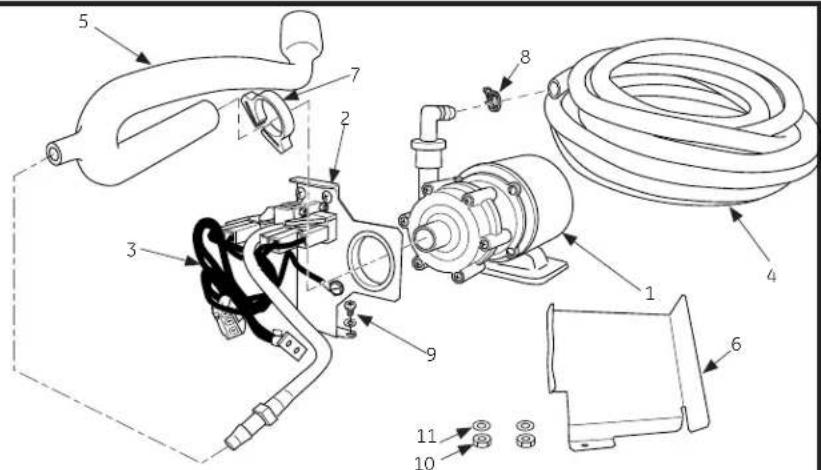
KIT CONTENTS:
1 - Pump and motor with check valve
2 - Switch mounting bracket assembled to switch assembly
3 - Wire harness
4 - Pressure hose (clear)
5 - Drain hose (white preformed)
6 - Stainless steel shield (for use in cube models only)
7 - Snap fit clamp
8 - Hose clamp
9 - 2 Screws with lock washers
10-2 Nuts
11-2 Washers
INSTALLING PUMP KIT
1 DISCONNECT ELECTRICAL POWER
WARNING

Electrical Shock Hazard
Death or serious injury can result from failure to follow these instructions.
• Service by a qualified service technician only.
- Disconnect power before servicing this product.
- Reconnect all grounding devices after service.
- Replace all parts and panels before operating.
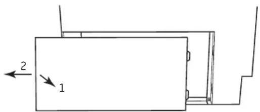
D. Remove the side service panel. Pull out on the left side (1) and back (2) to remove.
2 REMOVE BACK PANEL
A. Remove all ice if applicable.
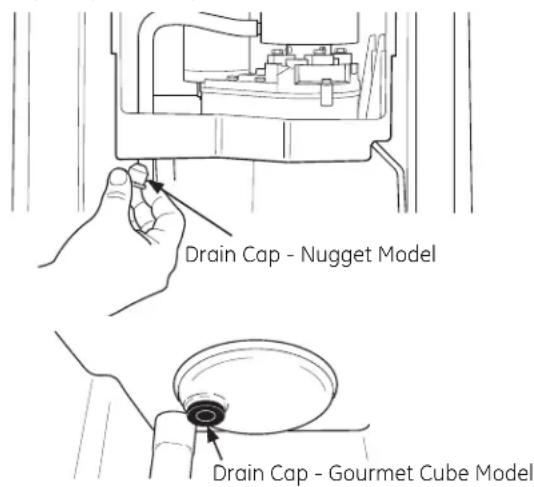
B. Drain reservoir by removing reservoir drain cap. Replace cap when water has drained.
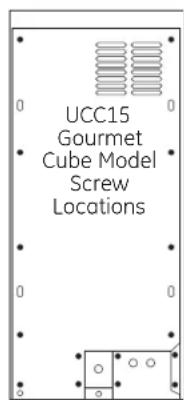
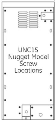
C. Remove the screws from the back panel (19 for gourmet cube models; 15 for nugget models).
3 REMOVE FRONT PANELS
A. Open the ice machine door all the way.
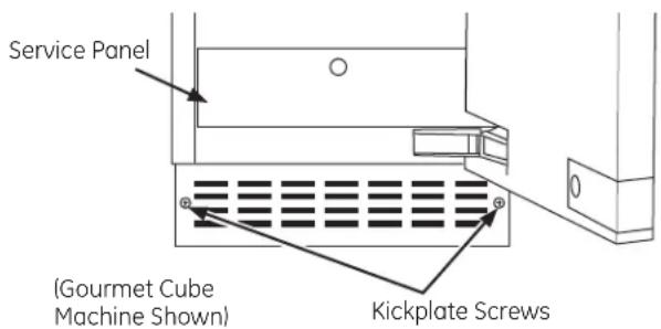
B. Remove the Service Panel.
C. Remove the Kickplate by removing the 2 screws securing it to the base.
4 REMOVE EXISTING DRAIN HOSE
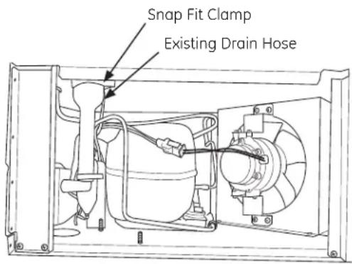
Remove the existing drain hose. The drain hose is the white tube with a white snap fit clamp on it in the upper left hand corner of the side service panel access area. Save the snap fit clamp. It will be used to install the new drain hose.
5 INSTALL THE PUMP KIT
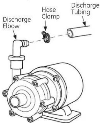
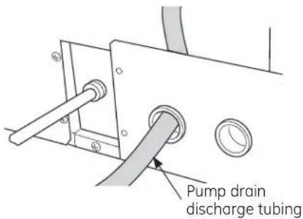
A. Uncoil the 10-foot long discharge tubing. Push one end completely onto the barbed discharge elbow of the pump and securely fasten it with the small metal hose clamp. Use pliers to open the hose clamp.
B. Route the other end of the discharge tubing through the routing panel in the back of the unit. Put the end of the discharge tube into a drain.
C. Place the pump over the bolts located on the base of the ice machine and secure with the two nuts and washers provided in the kit.

D. Route the straight portion of drain tube through the hole in switch assembly bracket.
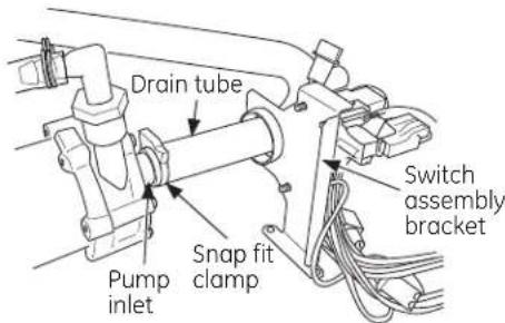
E. Connect drain tube to pump inlet and secure with the white snap fit clamp from the kit.
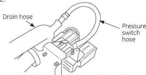
F. Connect the pressure switch hose to the drain hose.
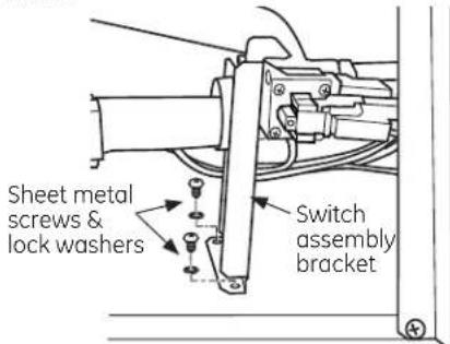
G. Mount the switch assembly bracket to the base using two provided sheet metal screws and lock washers.
H. Trace the black and white power cord from the switch assembly to the black and white power cord coming from the unit near the compressor. Make sure that the wires lay on the left side of the pump if you are facing the unit from behind. Unplug the current black and white wire's connection. Plug the black and white wire's connector from the unit into the black and white connector from the switch assembly. Repeat with the red and white connections. It is not necessary to replace the wire tie that is removed to disconnect the connector. Connect the 3-pin connector from the switch assembly bracket to the 3-pin connector on the pump.
INSTALLING PUMP KIT (Continued)
5 INSTALL THE PUMP KIT (Cont.)
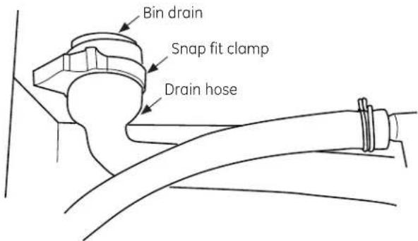
I. Refer to the unit's wiring diagram and re-check all electrical connections for proper placement. J. Connect drain hose to bin drain, and secure with the snap fit clamp reserved from removing the old drain hose.
6 FLUSH OUT THE DRAIN HOSE
A. Restore power to the unit. B. With the unit still OFF, pour several quarts of water into the bin. The drain pump should turn on and pump the water out of the bin, cycling on and off several times during the process. Pump cycling is normal since the pump-out rate of the drain pump is greater than the rate of drain through the bin. C. While the pump is discharging water, THOROUGHLY CHECK THE ENTIRE DRAIN SYSTEM FOR LEAKS.
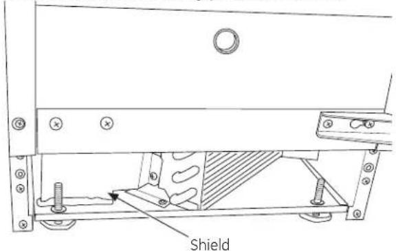
7 GOURMET CUBE ICE MACHINE ONLY
Attach stainless steel shield to side of condenser shroud using provided screws.
8 FINALIZE INSTALLATION
A. Re-install all panels and covers. B. Re-install unit into built-in or free-standing location. ENSURE THAT NO KINKS OCCUR IN WATER INLET OR DRAIN TUBING. Double-check for leaks! C. Restore potable water supply and restart the unit. Check unit to ensure proper operation and to allow a final check for leaks of any kind.
INSTALLATION DE L'ENSEMBLE DE POMPE
1 DÉBRANCHER L'ALIMENTATION ÉLECTRIQUE
! AVERTISSEMENT


- Installation Instructions
- Drain Pump Kit UPK3
- BEFORE YOU BEGIN
- WHAT YOU WILL NEED:
- Phillips screwdriver
- KIT CONTENTS:
- INSTALLING PUMP KIT
- DISCONNECT ELECTRICAL POWER
- WARNING
- Electrical Shock Hazard
- REMOVE BACK PANEL
- REMOVE FRONT PANELS
- REMOVE EXISTING DRAIN HOSE
- INSTALL THE PUMP KIT
- INSTALLING PUMP KIT (Continued)
- INSTALL THE PUMP KIT (Cont.)
- FLUSH OUT THE DRAIN HOSE
- GOURMET CUBE ICE MACHINE ONLY
- FINALIZE INSTALLATION
- INSTALLATION DE L'ENSEMBLE DE POMPE
- DÉBRANCHER L'ALIMENTATION ÉLECTRIQUE
- ! AVERTISSEMENT
Brand : GE
Model : UPK3
Category : Ice machine