Profile PKS7000BNTS - Oven GE - Free user manual and instructions
Find the device manual for free Profile PKS7000BNTS GE in PDF.

User questions about Profile PKS7000BNTS GE
0 question about this device. Answer the ones you know or ask your own.
Ask a new question about this device
Download the instructions for your Oven in PDF format for free! Find your manual Profile PKS7000BNTS - GE and take your electronic device back in hand. On this page are published all the documents necessary for the use of your device. Profile PKS7000BNTS by GE.
USER MANUAL Profile PKS7000BNTS GE
Installation Instructions
27" & 30" Electric Built-In Wall Ovens
Questions? Call us at 1.800.432.2737 or visit GEAppliances.com.
In Canada, call 1.800.561.3344 or visit GEAppliances.ca.
BEFORE YOU BEGIN
Read these instructions completely and carefully.
• IMPORTANT — Save these
instructions for local inspector's use.
• IMPORTANT — Observe all governing codes and ordinances.
- Note to Installer – Be sure to leave these instructions with Consumer.
• Note to Consumer – Keep these instructions for future reference.
• Skill level – Installation of this appliance
requires a qualified installer or electrician
• Proper installation is the responsibility of the installer.
• Product failure due to improper installation is not covered under Warranty.
• Product is for indoor use only.
ATTENTION INSTALLER: All electric wall ovens must be hard-wired (direct-wired) into an approved junction box. A plug and receptacle is NOT permitted on these products.
FOR YOUR SAFETY:
WARNING
Before beginning the installation, switch power off at the service panel and locking means to prevent power from being switched on accidentally. When the
service disconnecting means cannot be locked, securely fasten a prominent warning device, such as a tag, to the service panel.
Be sure the oven is securely installed in a cabinet that is firmly attached to the house structure. Weight on the oven door could cause the oven to tip and result in injury. Never allow anyone to climb, sit, stand or hang on the oven door.
Make sure the wall coverings, counters and cabinets around the oven can withstand the heat (up to 200^ F [93.3°C]) generated by the oven.
MATERIALS YOU MAY NEED
Junction Box
Wire Nuts
Strain Relief Clamp for 1/2" Conduit
36" (91 cm) of String
TOOLS YOU MAY NEED
1/8" Drill Bit and Electric or Hand Drill
T20 Screwdriver
Phillips Screwdriver
Wire Strippers
7/16" Nut Driver (combination ovens)
1/4" Nut Driver (30" combination ovens)
1 REMOVE PACKAGING MATERIALS
Failure to remove packaging materials could result in damage to the appliance. Remove all packing parts from oven, racks and heating elements. Remove protective film and labels on the outer door and control panel. Also, remove plastic on trims and panel, all tape around the oven and any shipping screws securing the oven to the base pad. Open oven door and remove literature pack and oven racks. Remove the bottom trim from the top of the oven. It will be installed at the end of the installation process. The trim is wrapped separately and taped to the top of the unit. Remove pedestal rails from separate box and set aside (30" Double Wall Ovens Only).
Consider recycling options for your appliance packaging material.
DESIGN INFORMATION
SINGLE OVEN INSTALLATIONS
The single oven may be installed in a cabinet alone or above a warming drawer. The single oven may also be installed side by side, below a countertop, or below specified cooktops. See the label on top of the oven for approved models.
DOUBLE AND COMBINATION OVEN INSTALLATIONS
A double or combination oven may be installed in a cabinet alone or above a warming drawer. See the label on top of the oven for approved models.
IMPORTANT: Always refer to individual installation instructions packed with each product for specific requirements.
2 PREPARE THE OPENING
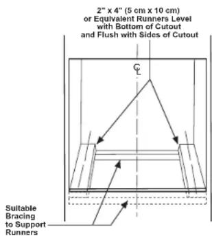
NOTE: If the cabinet does not have a solid bottom, two braces or runners must be installed to support the weight of the oven. For single ovens, the runners and braces must support 220 lbs (99 kg). For double and combination ovens, the runners and braces must support 400 lbs. (181 kg).
NOTE: If marks, blemishes or the cutout opening are visible above the installed oven, it may be necessary to add wood shims under the runners until the marks or opening are covered.
NOTE: If the cabinet does not have a front frame and the sides are less than 34 " (1.9 cm) thick, shim both sides equally to establish the cutout width.
text_image
2" x 4" (5 cm x 10 cm) or Equivalent Runners Level with Bottom of Cutout and Flush with Sides of Cutout Suitable Bracing to Support Runners2 A CUTOUT FOR SINGLE Ovens IN WALL CABINET
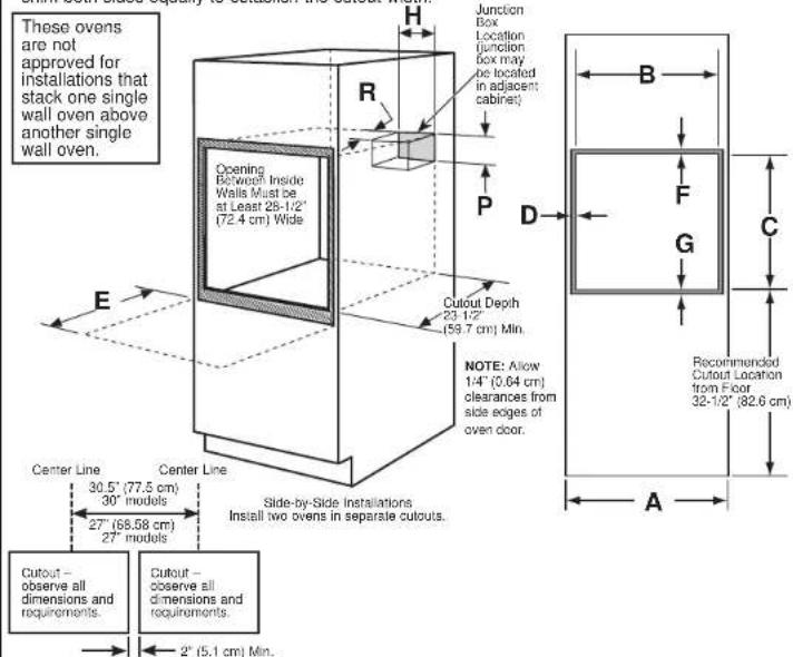
NOTE: If the cabinet does not have a front frame and the sides are less than 34 " (1.9 cm) thick, shim both sides equally to establish the cutout width.
text_image
These ovens are not approved for installations that stack one single wall oven above another single wall oven. Opening Between Inside Walls Must be at Least 25-1/2" (72.4 cm) Wide Center Line 30.5" (77.5 cm) 30" models 27" (68.58 cm) 27" models Cutout - observe all dimensions and requirements. Side-by-Side Installations Install two ovens in separate cutouts. H R P D B F G C A E NOTE: Allow 1-4" (0.64 cm) clearances from side edges of oven door. Recommended Cutout Location from Floor 32-1/2" (82.6 cm)| Dimension | Dimension Description | 27" Single Oven | 30" Single Oven |
| A | Cabinet Width | 27" (68.6 cm) | 30" (76.2 cm) |
| B | Cutout Width | 25" (63.5 cm) min.251⁄2" (64.1 cm) max. | 281⁄2" (72.4 cm) min.288⁄4" (72.7 cm) max. |
| C | Cutout Height | 271⁄4" (70.2 cm) min.281⁄2" (71.4 cm) max. | 271⁄4" (69.2 cm) min.2751⁄4" (69.4 cm) max. |
| D | Clearance from cutout - side edges* | 1" (2.5 cm) | 11⁄4" (1.75 cm) |
| E | Clearance to Adjacent Corners,Drawers, Walls, etc., When DoorIs Open | 23" (50.8 cm) min. | 23" (53.3 cm) min. |
| F | Clearance from cutout - top* | 1" (2.5 cm) min. | 1" (2.5 cm) min.(11⁄4" (3.2 cm) for PT9050,ZET11S and ZET1P) |
| G | Clearance from cutout - bottom* | 1" (2.5 cm) min. | 11⁄4" (3.2 cm) |
| H | Junction Box Location | 81⁄4" (22.2 cm) max.right side only | 9 1⁄2" (24.1 cm) max.right side only |
| P | Junction Box location | 5-1/4" (13.34 cm) max. | 5-1/4" (13.34 cm) max. |
| R | Junction Box location | 2-1/2" (6.35 cm) max. | 2-1/2" (6.35 cm) max. |
* Refers to minimum clearance required for wall oven installation and does not reflect actual product dimensions.
2 B CUTOUT FOR SINGLE OVENS – UNDER COUNTER
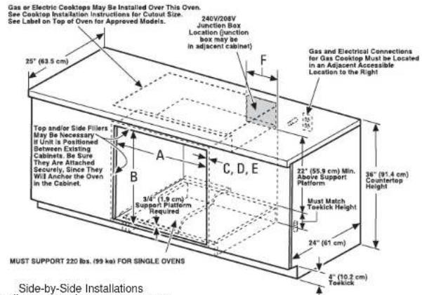
NOTE: These ovens are only approved to be installed under the specific models as labeled on the unit.
text_image
Gas or Electric Cooktops May be Installed Over This Oven. See Cooktop Installation Instructions for Cutout Size. See Label on Top of Oven for Approved Models. 240V/208V Junction Box Location (junction box may be in adjacent cabinet) F Gas and Electrical Connections for Gas Cooktop Must be Located in an Adjacent Accessible Location to the Right 25" (63.5 cm) Top and/or Side Fillers May Be Necessary it Unit is Positioned between Existing Cabinets. Be Sure They Are Attached Securely, Since They Will Anchor the Oven in the Cabinet. A B C, D, E 22" (55.9 cm) Min. Above Support Platform Must Match Toekick Height 36" (91.4 cm) Countertop Height 34" (1.9 cm) Support Platform Required B 24" (61 cm) MUST SUPPORT 220 lbs. (99 kg) FOR SINGLE Ovens 4" (10.2 cm) Toekick Side-by-Side Installations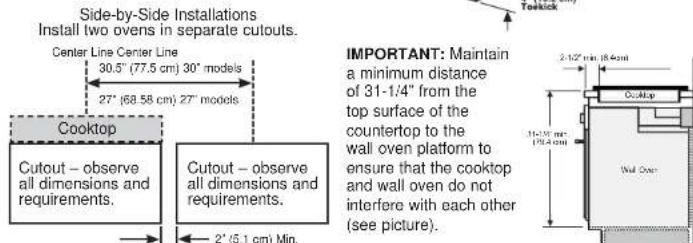
text_image
Side-by-Side Installations Install two ovens in separate cutouts. Center Line Center Line 30.5" (77.5 cm) 30" models 27" (68.58 cm) 27" models. Cooktop Cutout – observe all dimensions and requirements. Cutout – observe all dimensions and requirements. 2" (5.1 cm) Min. IMPORTANT: Maintain a minimum distance of 31-1/4" from the top surface of the countertop to the wall oven platform to ensure that the cooktop and wall oven do not interfere with each other (see picture).NOTE: One cooktop may be centered over either oven in the side-by-side installation.
| Dimension | Dimension Description 27" Single Oven 30" Single Oven | |
| A Cabinet Width 25" (63.5 cm) min. | 28 12 " (72.4 cm) min.28 12 " (72.7 cm) max. | |
| B Cutout Height 27 | 27 12 " (69.2 cm) min.27 12 " (69.4 cm) max. | |
| C Clearance from cutout - top" 1" (2.5 cm) 1"(2.5 cm) | (1 14 " (3.2 cm) forPT9050ZET1S and ZET1P) | |
| D Clearance from cutout - bottom" 1" (2.5 cm) 1 | 14 " (3.2 cm) | |
| E Clearance from cutout - side edges* | 14 " (1.75 cm) | |
| F Junction Box Location 8 | 9 12 " (24.1 cm) max.right side only | |
* Refers to minimum clearance required for wall oven installation and does not reflect actual product dimensions. Continue to Section 4.
2 C CUTOUT FOR DOUBLE OVENS (2 THERMAL OVENS)
NOTE: If the cabinet does not have a front frame and the sides are less than 34 " (1.9 cm) thick, shim both sides equally to establish the cutout width.
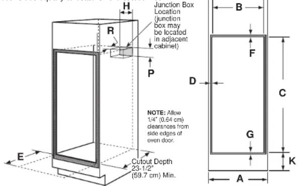
text_image
Junction Box Location (junction box may be located in adjacent cabinet) NOTE: Allow 1/4" (0.64 cm) clearnesses from side edges of oven door. Cutout Depth 23-1/2" (59.7 cm) Min. A B C D E F G K| Dim. | Description 27" Double Oven | 30" Double Oven with Pedestal | 30" Double Oven without Pedestal | |
| A | Cabinet Width 27" (68.6 cm) 30" (76.2 cm) 30" (76.2 cm) | |||
| B | Cutout Width 25" (63.5 cm) min. | 25/4" (64.1 cm) max. | 28/4" (72.4 cm) min.28/4" (72.7 cm) max. | 281⁄2" (72.4 cm) min.281⁄2" (72.7 cm) max. |
| C | Cutout Height | 491⁄4" (126.2 cm) min.50/4" (127.3 cm) max. | 511⁄4" (131.6 cm) min.511⁄4" (131.9 cm) max. | 50 1⁄4" (127.64cm) |
| D | Clearance from cutout - side edges* | 1" (2.5 cm) | 1⁄2" (1.75 cm) | 1⁄2" (1.75 cm) |
| E | Clearance to Adjacent Corners, Drawers, Walls, etc., When Door is Open | 23" (50.8 cm) min. 23" | (53.3 cm) min. 23" (53.3 cm) min. | |
| F | Clearance from cutout - top* | 1" (2.5 cm) min. | 1" (2.5 cm) min.(11⁄4" (3.2 cm) for PT9550,ZET2S and ZET2P) | 1" (2.5 cm) min.(11⁄4" (3.2 cm) for PT9550,ZET2S and ZET2P) |
| G | Clearance from cutout - bottom* | 1" (2.5 cm) min. | 11⁄2" (3.2 cm) | 11⁄2" (3.2 cm) |
| H | Junction Box Location | 81⁄4" (22.2 cm) max.right side only | 91⁄2" (24.1 cm) max. right side only | 91⁄2" (24.1 cm) max. right side only |
| K | Recommended Cutout Location from Floor | 131⁄4" (33.7 cm) | 12" (30.5 cm) | 12" (30.5 cm) |
| P | Junction Box location | 5-1/4" (13.34 cm) max. | 5-1/4" (13.34 cm) max. | 5-1/4" (13.34 cm) max. |
| R | Junction Box location | 2-1/2" (6.35 cm) max. | 2-1/2" (6.35 cm) max. | 2-1/2" (6.35 cm) max. |
* Refers to minimum clearance required for wall oven installation and does not reflect actual product dimensions. Continue to Section 3.

31-2000964 Rev. 1 11-21 GEA
2 D CUTOUT FOR COMBINATION OVENS (WITH UPPER MICROWAVE OVEN)
NOTE: If the cabinet does not have a front frame and the sides are less than 34 " (1.9 cm) thick, shim both sides equally to establish the cutout width.
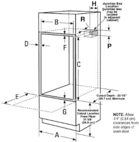
text_image
Junction Box Location (junction box may be located in adjacent cabinet) H B R D F C P E G A Recommended Cutout Location From Floor 21 5/8" (54.9 cm) Cutoff Depth - 23 1/2" (59.7 cm) Minimum NOTE: Allow 1/4" (0.64 cm) clearances from side edges of oven door.| Dim. | Description | 27" Oven with Microwave | 30" Oven with Microwave |
| A | Cabinet Width | 27" (68.6 cm) | 30" (76.2 cm) |
| B | Cutout Width | 25" (63.5 cm) min.25 1⁄4" (64.1 cm) max. | 28 1⁄2" (72.4 cm) min.28 3⁄4" (72.7 cm) max. |
| C | Cutout Height | 41 1⁄4" (104.5 cm) min.41 1⁄4" (104.8 cm) max. | 42 7⁄8" (107.2 cm) min.42 1⁄4" (107.3 cm) max. |
| D | Clearance from cutout - side edges* | 1" (2.5 cm) | 1 1⁄4" (1.75 cm) |
| E | Clearance to Adjacent Corners, Drawers, Walls, etc., When Door Is Open | 23" (58.4 cm) min. | 23" (58.4 cm) |
| F | Clearance from cutout - top* | 1" (2.5 cm) min. | 1" (2.5 cm) min. |
| G | Clearance from cutout - bottom* | 1" (2.5 cm) min. | 1 1⁄4" (3.2 cm) |
| H | Junction Box Location | 8 7⁄4" (22.2 cm) max.right side only | 9 1⁄2" (24.1 cm) max.right side only |
| P | Junction Box location | 5-1/4" (13.34 cm) max. | 5-1/4" (13.34 cm) max. |
| R | Junction Box location | 2-1/2" (6.35 cm) max. | 2-1/2" (6.35 cm) max. |
* Refers to minimum clearance required for wall oven installation and does not reflect actual product dimensions. Continue to Section 2E.
2 E SECURING UPPER MICROWAVE/ADVANTIUM OVEN TO CABINET
For double oven with microwave or Advantium upper ovens. Secure a wooden cleat to side of cabinet so that the upper oven can be secured to the cleat with provided screws
27" Cabinet requirements
- No shims (or cleats) required when cabinet is in minimum width condition.
- If cabinet is at maximum width condition, add wood shims to bring cabinet to minimum condition.
30" Cabinet requirements
- No shims (or cleats) required when cabinet is in minimum width condition.
- If cabinet is at maximum width condition, fix the wood cleats as shown in illustration.
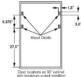
text_image
6.375" 27.5" Wood Cleats 1.5" 3.0" Cleal locations on 30" cabinet with maximum cutout condition2 F CUTOUT FOR INSTALLATION OVER A WARMING DRAWER
NOTE: Install the oven only with specific models listed on the label located on top of the oven.
NOTE: Additional clearances between cutouts may be required. Check to be sure the oven supports above the Warming Drawer location do not obstruct the required interior depth and height. When installing a Warming Drawer below a single, double, or combination oven, a separate 120V, 60 Hz, properly grounded receptacle must be installed. Refer to installation instructions packed with the Warming Drawer for specific installation requirements.
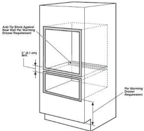
text_image
Anti-Tip Block Against Rear Wall Per Warming Drawer Requirement 2" (5.1 cm) Min. Per Warming Drawer RequirementContinue to Section 3 for Double Wall Oven with Pedestal. Otherwise, continue to Section 4.
3 A DETERMINING WHEN TO USE THE PEDESTAL (30" DOUBLE OVENS ONLY)
WHEN TO USE THE PEDESTAL
When replacing an older GE Appliances 30" double wall oven with a new GE Appliances model. Cutout height = 51-13/16" to 51-15/16". This is our traditional cutout height.
WHEN NOT TO USE THE PEDESTAL
When replacing a 30" double wall oven from another manufacturer (ie. Whirlpool) with a new GE Appliances 30" double wall oven. Cutout height = 50-1/4". You will need to verify that the existing cutout matches the 50-1/4" dimension.
If the new GE Appliances 30" double wall oven is being installed into new construction (ie. not a replacement), then the recommended installation is to use the Pedestal.
3 B PEDESTAL RAIL INSTALLATION (30" DOUBLE OVENS ONLY)
A. Position the pedestal rails with the top cutout toward the front of the opening and the flanges on the bottom, pointing toward the center. Locate each rail on the floor or cabinet runner, slightly inward from the side of the cabinet. Make sure the front of each rail is not protruding beyond the front of the cabinet opening.
B. Drill pilot holes and attach rails to runner or bottom of cabinet with provided hardware.
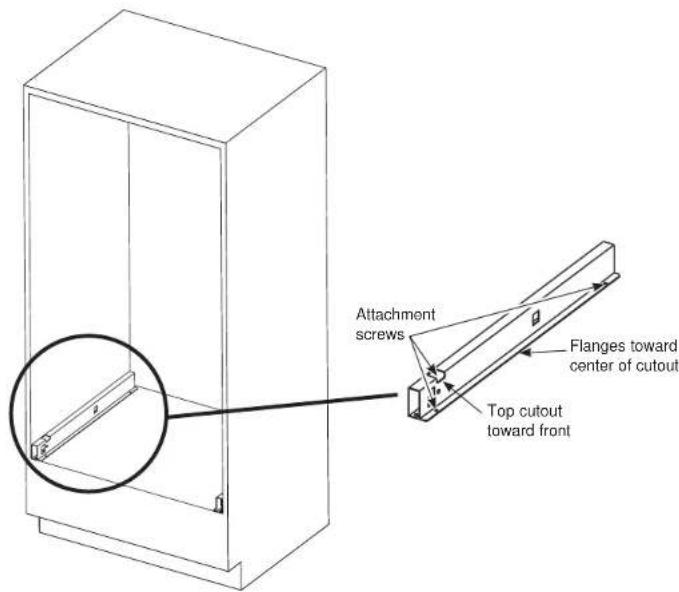
text_image
Attachment screws Flanges toward center of cutout Top cutout toward front4 A DOOR REMOVAL (RECOMMENDED FOR THERMAL Ovens)
WARNING
The door for the microwave oven on a combination oven
should never be removed, unless by a certified technician.
NOTE: Door removal is not a requirement for installation of the product but is an added convenience.
To remove the door:
A. Open the oven door as far as it will go.
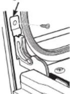
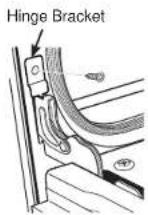
B. Remove hinge bracket, if equipped, from front frame and set aside. The hinge bracket must be replaced, if equipped, for proper door functionality when door is reinstalled.
C. Push both hinge locks down toward the door frame to the unlocked position. This may require a flat-blade screwdriver. DO NOT LIFT THE DOOR BY THE HANDLE!
D. Place hands on both sides of the door and close the oven door to the removal position (approximately 1"–2" [2.5 cm–5.1 cm] from the closed position).
E. Lift the door up and out until the hinge arms clear the slots. NOTE: The oven door is very heavy. Be sure you have a firm grip before lifting the oven door off the hinges. Use caution once the door is removed. Do not lay the door on its handle. This could cause dents or scratches.
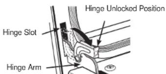
text_image
Hinge Unlocked Position Hinge Slot Hinge Arm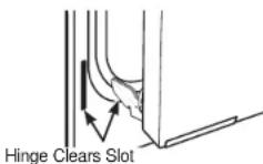
Hinge Bracket
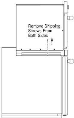
4 B SHIPPING SCREWS REMOVAL (FOR 30" COMBINATION OVEN UPPER OVEN ONLY)
Shipping screws must be removed as shown in illustration. You will need a 1/4" Nut Driver.
text_image
Remove Shipping Screws From Both Sides5 ELECTRICAL REQUIREMENTS
WARNING
This appliance must be properly grounded.
WARNING
To prevent fire or shock, do not use an extension cord with this appliance.
WARNING
To prevent shock, remove house fuse or open circuit breaker before beginning
installation.
WARNING
Improper connection of aluminum house wiring to copper leads can result in an e. Use only connectors designed for joining copper to aluminum and follow the intended procedure closely.
We recommend you have the electrical wiring and hookup of your appliance connected by a qualified electrician. After installation, have the electrician show you how to disconnect power from the appliance.
You must use a single-phase, 120/208 VAC or 120/240 VAC, 60 Hertz electrical system. If you connect to aluminum wiring, properly installed connectors approved for use with aluminum wiring must be used.
Effective January 1, 1996, the National Electrical Code requires that new construction (not existing) utilize a four-conductor connection to an electric oven. When installing an electric oven in new construction, a mobile home, recreational vehicle or an area where local codes prohibit grounding through the neutral conductor, refer to the section on four-conductor branch circuit connections.
Check with your local utilities for electrical codes which apply in your area. Failure to wire your oven according to governing codes could result in a hazardous condition. If there are no local codes, your oven must be wired and fused to meet the National Electrical Code, NFPA No. 70 – latest edition, available from the National Fire Protection Association.
5 ELECTRICAL REQUIREMENTS (CONT.)
This appliance must be supplied with the proper voltage and frequency and connected to an individual, properly grounded branch circuit, protected by a circuit breaker or fuse. See the rating plate located on the oven frame to determine the rating of the product.
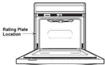
text_image
Rating Plate LocationRating plate is located on the oven side trim.
Use the chart below to determine the minimum recommended dedicated circuit protection:
| KW Rating240V | KW Rating208V | RecommendedCircuit Size(Dedicated) |
| ≤4.8 KW ≤4.1 | KW 20 Amp | |
| 4.9 KW-7.2 KW 4.2 | KW-6.2 KW 30 Amp | |
| 7.3 KW-9.6 KW 6.3 | KW-8.3 KW 40 Amp | |
| 9.7 KW-12.0 KW 8.4 | KW-10.4 KW 50 Amp |
DO NOT shorten the flexible conduit. The conduit strain relief clamp must be securely attached to the junction box and the flexible conduit must be securely attached to the clamp. If the flexible conduit will not fit within the clamp, do not install the oven until a clamp of the proper size is obtained.
The 3 power leads supplied with this appliance are suitable for connection to heavier gauge household wiring. The insulation of these 3 leads is rated for temperatures much higher than the temperature rating of the household wiring. The current-carrying capacity of the conductor is governed by the wire gauge and the temperature rating of the insulation around the wire.
6 MAKE ELECTRICAL CONNECTIONS
WARNING
WARNING Switch power off at the service panel and lock the service disconnecting means to prevent power from being switched on accidentally. When the service disconnecting means cannot be locked, securely fasten a prominent warning device, such as a tag, to the service panel.
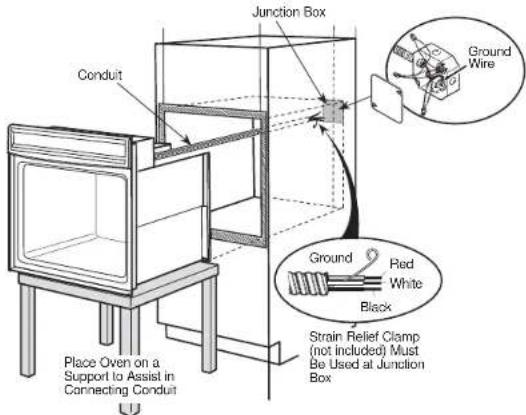
Place oven on table or platform even with the cutout opening. For a single oven, the platform must support 220 lbs. (99 kg); for a double or combination oven, the platform must support 400 lbs. (181 kg). Connect the flexible conduit to the electrical junction box as shown below ^7 . Position the conduit in such a manner that it will lie behind the unit in a natural loop when the oven is installed ^28 . You will need to purchase an appropriate strain relief clamp to complete the connection of the conduit to the junction box.
text_image
Junction Box Conduit Ground Wire Ground Red White Black Strain Relief Clamp (not included) Must Be Used at Junction Box Place Oven on a Support to Assist in Connecting Conduit*Ovens come equipped with a 40" or 54" long conduit. If a longer conduit is desired, there may be one available for your model. To check availability or order parts, call GE Appliances at 1.800.GE.CARES.
** Combination Oven with upper microwave oven - it is recommended to install the conduit through the side of the junction box as shown in the illustration above.
7 THREE-CONDUCTOR BRANCH CIRCUIT CONNECTION
NOTE: If residence leads are aluminum conductors, see WARNING in Section 5, Electrical Requirements.
When connecting to a three-conductor branch circuit, if local codes permit:
A. Connect the oven ground conductor along with the neutral (white) lead to the branch circuit neutral (white or gray in color), using a wire nut.
B. Connect the oven red lead to the branch circuit red lead and the oven black lead to the branch circuit black lead in accordance with local codes, using wire nuts.
C. Install proper strain relief clamp.
D. Install junction box cover.
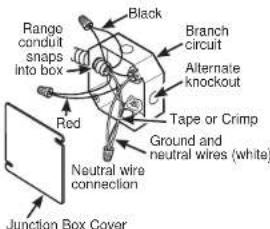
text_image
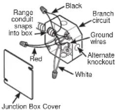
Range condits snaps into box Red Black Branch circuit Alternate knockout Tape or Crimp Ground and neutral wires (white) Neutral wire connection Junction Box Cover8 FOUR-CONDUCTOR BRANCH CIRCUIT CONNECTION
NOTE: If residence leads are aluminum conductors, see WARNING in Section 5, Electrical Requirements.
When connecting to a four-conductor branch circuit, if local codes permit:
A. Free the neutral (white) lead from being restrained to any other wires. If necessary, cut the neutral (white) lead and then re-strip it to expose the proper length of conductor.
B. Attach the appliance grounding lead (green or bare copper) in accordance with local codes.
C. Connect the oven neutral (white) lead to the branch circuit neutral (white or gray) in accordance with local codes, using a wire nut.
D. Connect the oven red lead to the branch circuit red lead and the oven black lead to the branch circuit black lead in ac cordance with local codes, using wire nuts.
E. Install proper strain relief clamp.
F. Install junction box cover.
text_image
Range condul snaps into box Black Branch circuit Ground wires Alternate knockout White Red Junction Box Cover9 SLIDE OVEN INTO OPENING
A. Loop (do not tie) a 36" (91 cm) string around the conduit before the oven is slid into place. This will keep the conduit from falling behind the oven.
B. Lift oven into cabinet cutout using the oven opening as a grip. Carefully push against oven front frame. Do not push against outside edges.
C. As you slide the oven back, pull the string so that the conduit will lie on top of the oven in a natural loop. For a combination oven, pull the conduit so that it sits above the lower oven on the left side (as viewed from the front).
D. When you are sure the conduit is out of the way, slide the oven 34 way back into the opening. Remove the string by pulling on one end of the loop.
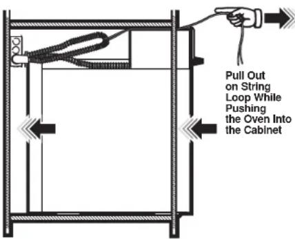
text_image
Pull Out on String Loop While Pushing the Oven Into the Cabinet10 A INSTALL MOUNTING SCREWS (UPPER OVEN ON COMBINATION OVENS)
- Slide the oven the remaining way into the opening so that the side flanges and control panel are against the cabinet frame. Make sure that the oven is centered in the opening.
- Open the door, place a turntable tray in the oven and make sure that the tray in the unit is level.
• Drill pilot holes through the side flanges. - Drive the color-matched screws into the side flanges. It is recommended that the screws be hand tightened.
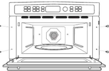
natural_image
Line drawing of an oven with control panel and vent, showing interior airflow or ventilation (no text or symbols)10 B INSTALL MOUNTING SCREWS (THERMAL OVENS)
⚠ WARNING
WARNING Mounting screws must be used. Failure to do so could result in the oven falling out of the cabinet, causing serious injury.
NOTE: During oven mounting step, ensure that no damage is done to oven gasket which lines the edge of oven cavity.
NOTE: Before drilling the pilot holes, make sure the oven is pushed as far back into the opening as it will go and is centered.
NOTE: If the cabinet is particle board, you must use #8 x 3/4" particle board screws. These may be purchased at any hardware store.
A. Drill through the mounting holes (top and bottom) of the side trim for the #8 mounting screws provided.
B. Secure the oven cabinet with the screws provided.
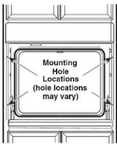
text_image
Mounting Hole Locations (hole locations may vary)The Screws Must Be a Minimum of 1/4" (6 mm) From the Front of the Cutout.
Some models have custom handles. Please follow the instructions with the handles for proper installation.
11 BOTTOM TRIM INSTALLATION
With oven installed, attach the bottom trim through its mounting holes in front vertical brace using two trim screws provided. Bottom trim lip must be placed under flange of bottom air duct.
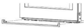
Single, Combination, and Double Wall Oven Installations without a Pedestal
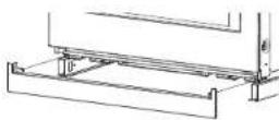
Double Wall Oven Installations with a Pedestal
IMPORTANT: If this unit is ever removed from the cabinet or the oven is ever pulled out for service, the bottom trim must be removed first or damage to the trim will occur.
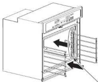
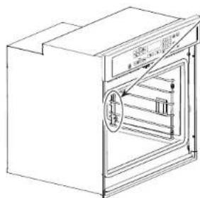
12 OVEN RACK GUIDE INSTALLATION (IF APPLICABLE)
A. Locate included oven rack guide mouting hardware.
B. Place oven rack guides on cavity wall studs with metal posts towards back of cavity as shown.
C. Install guides using the 8 provided mounting nuts.
text_image
Technical diagram of an oven with labeled components and directional arrows indicating flow or movementMetal Posts to be installed in the rear of cavity
text_image
Technical diagram of a refrigerator with labeled parts and directional arrows indicating internal structureOven rack guide shown in place.
13 REPLACING THE THERMAL OVEN DOOR
NOTE: The oven door is heavy. You may need help lifting the door high enough to slide it into the hinge slots. Do not lift the door by the handle. A. Lift the oven door by grasping each side.
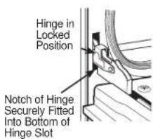
B. With the door at the same angle as the removal position (approximately 1"-2" [2.5 cm-5.1 cm] from the closed position), seat the notch of the hinge arm into the bottom edge of the hinge slot. The notch of the hinge arm must be fully seated into the bottom of the slot.
C. Fully open the door. If the door will not fully open, the indentation is not seated correctly in the bottom edge of the slot.
D. Push the hinge locks up against the front frame of the oven cavity, to the locked position.
E. Replace hinge bracket, if equipped, to ensure proper door functionality.
F. Close the oven door.
text_image
Hinge in Locked Position Notch of Hinge Securely Fitted Into Bottom of Hinge Slot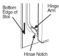
text_image
Bottom Edge of Slot Hinge Arm Hinge Notch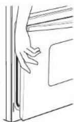
14 FINAL INSTALLATION CHECKLIST
- Check to make sure the circuit breaker is closed (RESET) or the circuit fuses are replaced.
- Be sure power is in service to the building.
- Check that all packing material and tape have been removed. Failure to remove these materials could result in damage to the appliance once the appliance has been turned on and surfaces have heated.
- Remove all items from inside the oven.
- Check to be sure that the mounting screws are installed and flush with the side trim (see Section 10).
- Check that the bottom trim is installed properly (see Section 11).
- Ensure that air duct opening at bottom of unit is free of obstructions.
- Check that oven rack guides (if applicable) are installed correctly and oven racks function smoothly.
- If applicable - install handles following handle installation instructions and check that both ends are secured.
OPERATION CHECKLIST
- Turn on the power to the oven (refer to your Owner's Manual). Verify that the bake and broil units and all cooking functions operate properly.
• See your Owner's Manual for the troubleshooting list. - Be sure all of the oven controls are OFF before leaving the oven.
INSTALLATIONS D'UN FOUR DOUBLE OU COMBINÉ
natural_image
Line drawing of an oven with control panel and decorative vent (no text or symbols)10 B INSTALLER LES VIS DE MONTAGE (FOURS THERMIQUES)
▲AVERTISSEMENT
12 INSTALLATION DU GUIDE DES GRILLES DU FOUR (SI APPLICABLE)

31-2000964 Rev. 1 11-21 GEA