HW AM12KE - Air Conditioning Amcor - Free user manual and instructions
Find the device manual for free HW AM12KE Amcor in PDF.

| Product type | Split air conditioner |
| Brand | Amcor |
| Model | HW AM12KE |
| Power supply | 220-240 V, 50 Hz, 16 A |
| Dehumidification capacity | 24 L/24h |
| Operating modes | Cooling, heating, dehumidification, ventilation, auto, night, turbo |
| Set temperature range | 18 °C - 30 °C |
| Filter | Washable filter (warm water and mild detergent) |
| Remote control | With LCD display, AAA battery |
| Timer function | Adjustable delayed start and stop |
| Automatic restart | After a power cut |
| Unit type | Split (indoor and outdoor unit) |
| Max distance between units | 4 m |
| Minimum elevation difference | 1 m (indoor unit higher) |
| Maintenance | Dust the indoor unit with a dry cloth, clean filters regularly |
| Safety | Earth connection mandatory, 16 A fuse, damaged cord replaced by professional |
Frequently Asked Questions - HW AM12KE Amcor
User questions about HW AM12KE Amcor
0 question about this device. Answer the ones you know or ask your own.
Ask a new question about this device
Download the instructions for your Air Conditioning in PDF format for free! Find your manual HW AM12KE - Amcor and take your electronic device back in hand. On this page are published all the documents necessary for the use of your device. HW AM12KE by Amcor.
USER MANUAL HW AM12KE Amcor
REplacement DES PILES
Thank you for choosing this innovative Amcor air conditioner. We suggest that you keep this manual in a safe place for future reference. It describes the many benefits and advanced features this unique product has to offer. Before you use your new air conditioner you should carefully read these instructions to maximise this product's performance.
For over 50 years Amcor has specialised in complete indoor environmental control, manufacturing and marketing; dehumidifiers, portable air conditioners, coolers, air purifiers, ionisers and aroma therapy scent diffusers. These world class products incorporate the latest technological developments.
SAFETY INSTRUCTIONS
IMPORTANT!
- The inside unit is designed for indoor operation only.
Rating: This unit must be connected to a 220-240 V / 50 Hz earthed outlet. - The installation must be in accordance with regulations of the country where the unit is used.
If you are in any doubt about the electrical installation, have it checked and if necessary modified by a qualified electrician.
- The air conditioner is safe. However, as with other electrical appliances, use it with care.
- Keep the remote control out of the reach of children.
- Do not clean the air conditioner by spraying it or immersing it in water.
- Do not insert any object into the opening of the air conditioner.
- Disconnect it from the mains before cleaning the unit or any of its components.
- Never connect the unit to an electrical outlet using an extension cord. If an outlet is not available, one should be installed by a licensed electrician.
WARNING
- Never operate this appliance if it has a damaged cord or plug. Do not lead the cord over sharp edges.
- A damaged supply cord should be replaced by the manufacturer, its service agent or a qualified person in order to avoid a hazard.
- Any service other than regular cleaning or filter replacement should be performed by an authorized service representative. Failure to do so could result in a loss of warranty.
Do not use your air conditioner when:

the power cord is damaged.
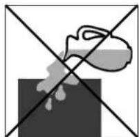
there is a change of liquids falling on the unit.
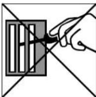
ther is a risk of interference from foreign objects.
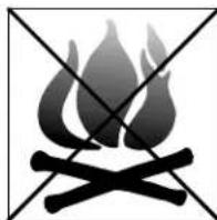
it a close to a heat source.
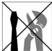
This air conditioner is not made for DIY repair.
HOW IT WORKS
The compressor (6) in the exterior unit compresses the refrigerant into a high-temperature, high-pressure gas. When this gas flows along the cooling fins of the condenser (7), heat is exuded and the gas condenses into a liquid, which is led to the evaporator (1) in the interior unit. The liquid expands into a gas at a low temperature and low pressure is converted.
This gas absorbs the warmth of the air in the room, the cooled air is blown back into the room and the heat is led to the compressor along with the gas.
A fan (3) draws the air (a) over the filter (2) and blows the cooled air (b) back into the room.
A fan (8) draws air over the condenser and blows warm air (d) away.
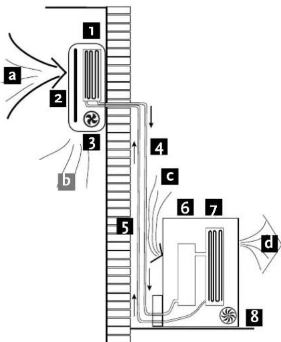
- evaporator 5. liquid line
2.filter 6.compressor
3.fan 7.condenser - gas line 8. fan
Heating.
The system operates in reverse: the condenser works as an evaporator, the evaporator as a condenser: warm air is blown into the room. This is ideal for cool days when the main heating is not on, or not yet on.
Dehumidifying
As with cooling, the moisture in the air condenses on the cold evaporator at room temperature
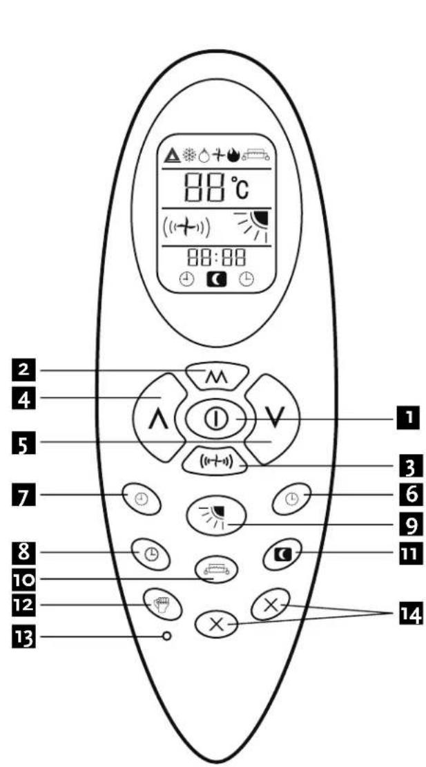
REMOTE CONTROL
LCD display:

auto
cool
dehumidify
fan
heat

electric
heating
(not on these models)

operature

speed

low direction


timer off
sleep mode
timer set
Buttons:
- ON/OFF
- mode (cool, heat, dehumidify)
- fan speed
- increase (temperature, time)
- decrease (temperature, time)
- timer setting
- timer cancelling
- clock
- swing (adjust the louvers)
- heater
- sleep mode
- turbo
- reset
- spare
Using of the remote control
The remote control signal has a range of up to 8m . Point the remote control at the receiver in the interior unit.
A beep confirms that the remote control signal has been received.
See page 45 for replacing the batteries.
OPERATION
General
- Turn the appliance on with the button [1]. This activates the most recent setting.
- The on/off button turns the appliance off; the type of operation set at that time is stored in the memory.
- The desired temperature is set with the up [4] and/or down [5] button, within the limits of the thermostat: 18^ - 25^ .
- Use the fan button (to set) the fan speed at low: , medium: , high: (1 + 1) or automatic (the symbol on the display will flash). The fan speed in the automatic setting is determined by the difference between the set temperature and the room temperature.
Setting the time
The time must be set after initial installation and at the start of a new period of use. With batteries (new, if necessary) in the remote control:
Press the clock button to set the time. Use the up button for hours and the down button for minutes.
Cool
- Press the mode button until the cool symbol appears.
- Set the desired temperature.
- Use the fan button (to set) the fan speed.
Heat
- Press the mode button until the heat symbol appears.
- Set the desired temperature.
- Use the fan button (to set) the fan speed.
Dehumidify (9KE max. 17 L/24h, 12KE max. 24 L/24h)
- Press the mode button until the dehumidify symbol appears.
- Set the desired temperature.
- The fan button does not work in dehumidify mode. The fan speed will always be low in this mode.
Fan mode
- Press the mode button until the fan symbol + appears.
- Set the desired temperature.
- Use the fan button (to set) the fan speed.
Sleep mode
- Press the mode button until the heat-cool- auto mode symbol appears.
- Set the desired temperature.
- Press the sleep mode button is symbol will appear on the display. Cancel the sleep mode by pressing this button again.
- The fan speed is low in sleep mode.
Auto mode
- Press the mode button until the auto mode symbol appears.
- The difference between set temperature and room temperature determines how the appliance operates: cool, heat, fan or dry. The up and down buttons will not work.
- Use the fan button (to set) the fan speed.
Timer off function
- Press the mode button until the symbol appears for the operation you want.
- Set the desired temperature.
- Use the fan button ((1 + 1)) to set the fan speed.
- Press the timer off button to set the time. Use the up button for hours and the down button for minutes. Once the time you have set has elapsed, the appliance will switch itself off. To cancel the timer off function before the set time has elapsed, press the timer off button again.
Timer on function
- The appliance is switched off.
- Press the timer on button to set the time. Use the up button for hours and the down button for minutes.
Set the desired operation, temperature, fan speed, etc. Once the set time has elapsed, the appliance will switch itself on. To turn off the timer on function before the set time has elapsed, press the timer on button again.
Turbo
- Press the mode button until the fan symbol appears.
- Set the desired temperature.
- Use the fan button (to set the fan speed).
- Press the turbo button The fan and compressor will run at maximum speed for 15 minutes, then at previously set speeds.
IMPORTANT
Auto restart
The air conditioner will automatic restart when electricity is restored after a power cut. If in doubt, check the settings.
Range of internal thermostat
The internal thermostat can be set at a desired temperature between 18 and 30^ . Note that whether the desired value is achieved depends on conditions in the room.
Range of heat pump function
The heat function can be used when the external temperature is approximately 10^ or higher.
Note that it may not operate properly at lower external temperatures.
Capacity
The required cooling or heating capacity depends greatly on the location and/or use of the room where the air conditioner is installed. Strong sunlight and the presence of people, lights or equipment create an additional heat load.
Normal living spaces require about 100 W per square metre of floor surface. In strong sunlight or if other sources of heat are present, this may be as much as 350 ~W / m^2 .
For your air conditioner's specifications, see pages 58/59.
Tip: on warm days, let the air conditioner cool the room as much as possible during the night. Cold walls and furniture will help to keep the room pleasant during use. Avoid strong sunlight.
Emergency start
In the event of a problem, the air conditioner can be operated using the emergency button under the panel in the interior unit. Open the front panel and press the button.
The air conditioner will:
- heat if the room temperature is 20^ or less
- cool if the room temperature is 25^ or more
and for values in between: dehumidify in a model without a heat pump and in a model with a heat pump in fan mode.
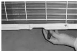
FILTERS
Turn the appliance off and remove the plug from the outlet.
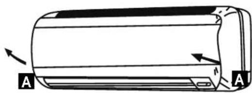
Opening: at the A recesses, pull the front part up. The front part will stay horizontal (turn up 90^ ).
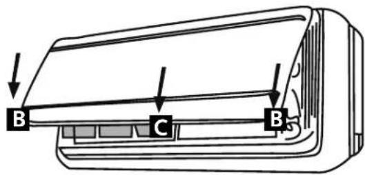
Closing: press the front part down at the sides at B and in the middle at C. Make sure it is properly closed (click).
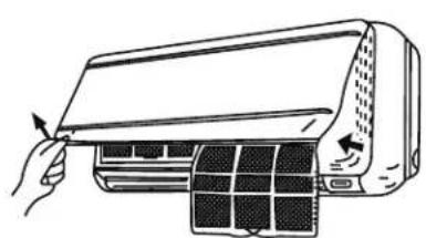
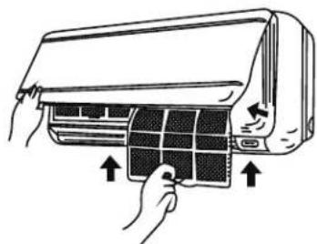
- Hold the front part open (or put it in horizontal position) and remove the filter(s).
- Tap the filter gently or use a vacuum cleaner to remove dirt. If the dust filter is very dirty, it may be washed in lukewarm water with a very small amount of neutral detergent. Rinse well and allow to dry completely (not in direct sunlight or near a source of heat).
- Keep the grid panel open and reinstall the filter(s). Press the panel shut; a click indicates it is closed properly.
- Plug the appliance back in and turn it on.
CLEANING
Turn the appliance off and remove the plug from the outlet.
Interior unit
Dust regularly with a dry cloth or slightly damp paper towel.
Never use chemicals or solvents. Never spray a liquid in or over the appliance.
Exterior unit
Remove dirt and keep the air intake and exhaust openings free of leaves, etc.
Cleaning with chemicals may cause damage.
END OF PERIOD OF USE
If the air conditioner is not going to be used for an extended period:
- set in fan mode on a slightly warm day so that the inside of the appliance dries out.
- remove the plug from the outlet and the batteries from the remote control.
- clean filters as well.
START OF PERIOD OF USE
If the air conditioner is to be used again after an extended period:
- check that the air intake and exhaust openings of the interior and exterior units are not blocked. Remove all dirt and obstacles.
- check that there is a filter.
- check that the condensation outlet drains properly.
- install 2 AAA batteries in the remote control.
- dust the interior unit.
- turn the appliance on, set the time and desired setting.
Note: make sure condensation is drained freely and that there is no obstacle such as algae growth, otherwise leaks may occur.
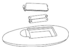
REPLACING THE BATTERIES
- remove the cover.
- replace the AAA batteries, + to + and - to -.
- install the cover.
- press the on/off button; if no symbols appear on the display, the batteries are empty or have been incorrectly installed.
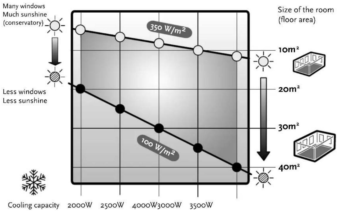
Which room is best suited for the Air Conditioner?
A suitable room depends on the cooling capacity, sun location, window area, presence of heat sources (lamps, appliances, number of people etc.). Take this into account! Rule of thumb, in average sunshine conditions and no presence of other heat sources: 100W per square metre (thus a cooling capacity of 3500W is best placed in a 35m^2 room).
SAFETY ASPECTS
Check the network voltage.
Make sure that the existing network voltage corresponds to the value specified on the type tag on the appliance.
Keep the work area tidy.
Carelessness in the work area can lead to accidents.
Use the right tools.
Do not use tools that are not sturdy enough for heavy work. Use reliable tools suitable for the purpose for which they are intended.
Wear a mask and eye and ear protection.
When doing work which may produce splinters or dust and when working over your head always wear eye protection and a well-fitting face mask. Wear ear mufflers in noisy conditions.
Extension cord when working outdoors.
Only use approved and correspondingly marked extension leads and sockets during work out of doors.
Check electrical equipment for any damage.
Never use equipment with a switch that does not work.
Be careful when working on steps, ladders and scaffolding.
Be extra careful when working on an elevated surface. Make sure that stepladders, steps, ladders and scaffolding are placed correctly and cannot slip.
Electrical cables, gas and water pipes etc.
Important safety aspect for work with drilling equipment:
Make sure that when drilling you cannot strike electrical cable, gas or water pipes.
Check the wall with a duct/cable detector before you start drilling.
Is everything clear?
Once you have familiarised yourself with the safety recommendations and have learnt from the user's manual how to use the tools, you can start working. By following the instructions and recommendations of the manufacturers you can be sure that you are working as safely as possible.
Keep these guidelines!
SAFETY
Read the section on safety aspects and these instructions before you start.
Stick to the work sequence and working method shown here.
For technical or commercial reasons, the manufacturer may make changes to the appliance or component parts, without general notification. You can consult your supplier about this.
IMPORTANT:
- This appliance must be connected to an earthed socket for 230V / 50Hz , with a 16A fuse.
- The connection to the national grid must be carried out in agreement with the safety standards as regards the installation of electrical household appliances applicable in the country of use.
If in doubt have the electrical installation checked and if necessary modified by a qualified electrician
Ensure you have:
- a well lit and a work area clear of clutter.
- a well thought out and pre-arranged work plan.
sound tools and reliable implements. - protection: safety goggles, ear protection, mask, hardhat, work shoes and work gloves.
The external unit must be lifted and put in place by two people.
YOUR
AIR
CONDITIONER
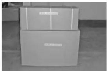
The split air conditioner comes in two boxes:
- box with internal unit with the necessary ducts
- box with external unit and tools.
Carefully take everything from the boxes. The packaging material must be kept out of reach of children
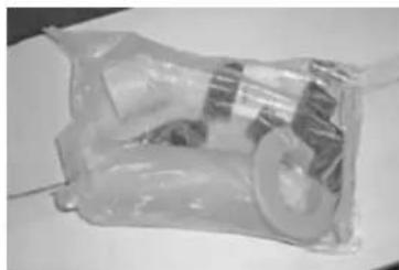
Additionally supplied parts and tools:
- screws and plugs for the attachment plate of the internal unit
- sleeve with collar for the hole through the wall
- pipette for condensation water drainage of the external unit
- 4 rubber footrests for the external unit
- 2 spanners for the valves of the external unit
- socket wrench for valves of the external unit
RECOMMENDED TOOLS AND IMPLEMENTS
hammer drill and ordinary drill electrical screwdriver
- duct detector - hammer
- tape measure - spirit level
- pencil and chalk - stepladder
- pipe wrench - cover to protect room floor
- duct trough and pipe brackets (if needed)
PU foam or silicone sealant (if needed)
WHERE TO PUT THE APPLIANCE?
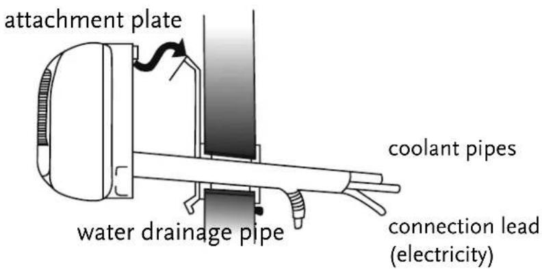
The maximum distance between the internal and external unit is 4m (the length of the freezing tubes and electricity cable). The internal unit must hang at least 1m higher than the top of the external unit.
The place for the internal unit
- on a wall in which a hole of 65 mm (size of the sleeve) can be made for the connection with the external unit. For a hole in a concrete wall special equipment is required; leave this to a specialised company. Check the selected place with a duct detector to make sure that there are no ducts.
- distance to ceiling at least 15cm , free space left and right at least 50cm .
- the cool air must be able to flow easily through the whole room.
- in the middle, not near a window or door is the most suitable place.
- it must be accessible to the filter for cleaning purposes.
- at least 1 m away from TV, video and similar equipment and from fluorescent lamps.
- an earthed socket must be present at a distance of no more than 1.5m (the length of the lead to the internal unit). If necessary have a socket fitted by a registered electrician in accordance with any applicable regulations. The internal unit gets its electricity from the external unit through the cable going along the freezing tubes.
The place of the external unit
- must be strong enough to support the weight of the external unit. That can be on the ground, on a flat roof (provided you can fit a suitable base plate there to attach the external unit to; prevent leakage of your roof) or on wall supports. If necessary reinforce the place chosen; if the place is not strong enough that can lead to excessive vibration and noise.
- sufficient free-flowing air current, as little as possible exposed to rain and direct sunlight and a draining possibility for the condensation water.
- where expelled air and noise do not lead to nuisance; not where there is high atmospheric humidity, not in the vicinity of grease or oxidising gases.
- free distance to the rear at least 15cm , to the sides and to the front at least 50cm . Allow space for maintenance work.
INTERNAL UNIT
To reduce the risk of leakage the internal unit must be hung absolutely level. The water catcher in the internal unit with the condensation water drainage connected to it must be clean and free from any obstruction, so that the condensation water can drain off unhindered (otherwise risk of leakage).
Once the place for the internal unit has been determined, you can start fixing the internal unit. Note that fixing it is your own responsibility.
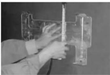
A. Attachment plate
Mount the attachment plate level on a firm base, measure well and draw holes for the screws.
TIP. Fix the plate not too firmly with a screw, put the plate in horizontal position with the help of a spirit level, and then mark the holes for the other screws. Take the screw out again, drill all holes, put plugs in and screw the plate tight.
Drill the 8 holes 6.4mm (2.5") wide and 30~mm deep.
Use the additionally supplied plugs.
Fix the attachment plate firmly with the additionally supplied screws.
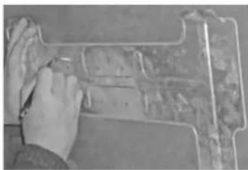
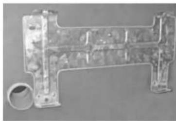
B. Hole through the wall for the duct
The hole with a diameter of 65mm and slanting a bit towards the outside in a downward direction (10 - 15mm) for better condensation water drainage, can be made inside the space of the hood and will thus remain out of sight. If necessary leading it through more to the left is possible. In that case cover troughs are available in specialist stores.
Area for the hole.
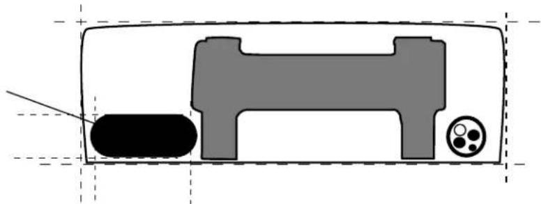
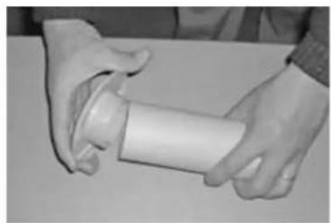
Put the additionally supplied sleeve in place and if necessary use the cover collar on the inside. If necessary saw the sleeve to the right length.
C. Mains lead
Inspect where the mains lead must come out of the internal unit, left or right. Chip off the small plate for the lead, take the lead out and fix it temporarily with tape, so that it will not be in the way when mounting the internal unit.
Get someone to help you mount the internal unit and thread the duct through.
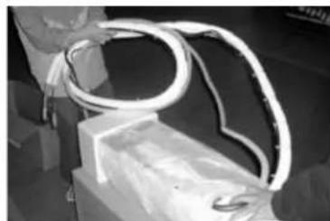
D. Duct
Carefully and without bending uncoil the bundle of ducts and thread the end bit through the hole with the sleeve.
E. Mounting
Lift the internal unit up and hang it on to the 4 lips on the attachment plate, while the ducts are being threaded through. Check whether the internal unit hangs on the 4 lips. If necessary have someone on the other side of the wall guide the ducts that are threaded through.
Pay close attention to the condensation water drainage pipe. Make sure that this duct runs easily and that it is laid with a downward slant. Make sure that the insulation has not shifted, no blank duct may be visible, because otherwise condensation may form here (risk of leakage).
Once the internal unit hangs well (level and not leaning to left or right) the external unit can be put in place.
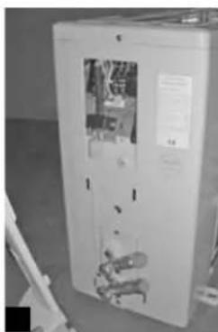
EXTERNAL UNIT
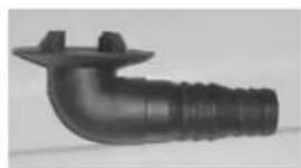


Drainage pipe
Fix the drainage pipe to the base plate. If necessary a drainage hose (not included) leading to a drain can be attached to this.
On the ground or on the roof the condensation water can usually drain off freely.
Check that this does not cause nuisance to anyone and that it can cause no damage.
Fixing the external unit
Place the rubber footrests and screw the unit thoroughly on a strong base.
Keep 50 cm of free space around the unit
The external unit can be fitted on special base plates or on a wall support.Consult your installer
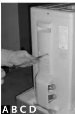
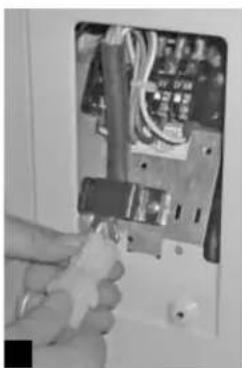
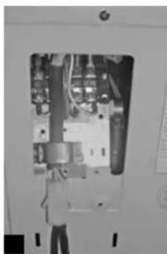
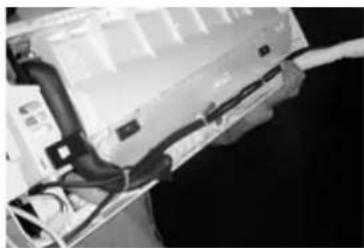
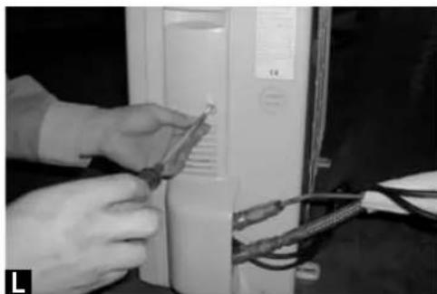
Connecting the electricity
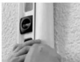
Unscrew the protective cover [A] [B].
The electricity for the external unit comes from the internal unit through the cable with a special little pin contact which clicks into the contact socket [C].
Check that this connection is properly fixed [D].
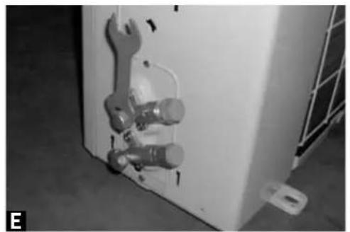
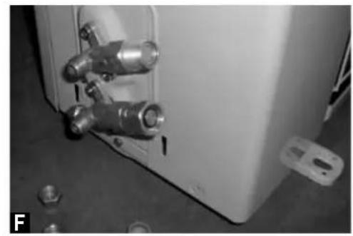
Ducts
Remove the protective caps of the valves [E] and the protection caps of the duct [F].
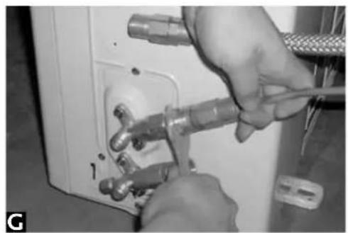
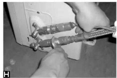
First tighten the thin duct on the upper valve [G]. Then tighten the thick duct on the lowest valve [H].
Check for leakage.
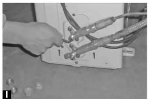
Open the upper valve with the socket wrench [I].
Check on both connections for leakage, by applying a sponge with soap-suds to the valves.
Close the valve immediately with the socket wrench in case of a leakage.
Call for assistance of your installer if, after you have checked that the ducts are well fitted, there is nevertheless a leakage. Keep the valves closed!
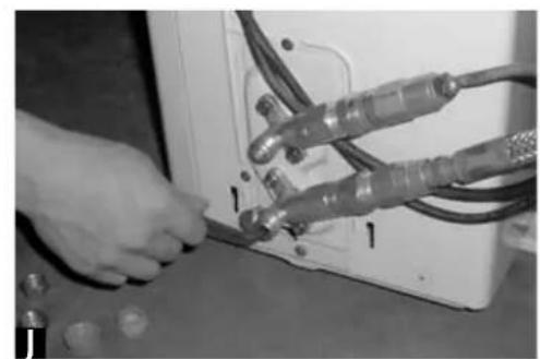
If there is no leakage, open the bottom valve with the socket wrench [J].
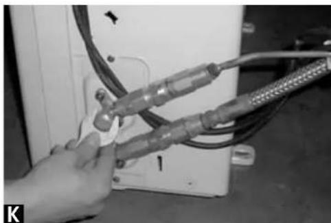
Once the freezing tubes are properly fixed and show no leakage, the protective caps can be put back again on the valves [K].
Screw the protective cover back on the external unit [L].
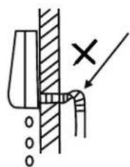
Fix the piping vertically on the wall with duct through and pipe brackets, available at DIY-stores.

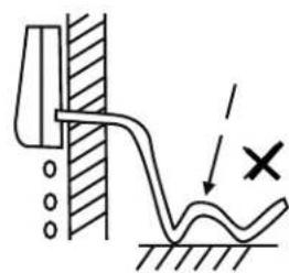
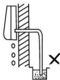
Lead the water drainage pipe to a suitable drainage point, making sure it can flow through freely.
Keep the protective caps of the links and valves and the additionally supplied tools carefully stored.
DISCONNECTING THE EXTERNAL UNIT
Notice: the quick-couplers are meant for one-off connection! The guarantee does not cover multiple installation.
Should it be necessary to disconnect, then go about it as follows:
- ask someone to help you operate the air conditioner via the remote control,
- put the desired temperature at 18^ C
- start the air conditioner, wait until you can also hear the compressor turning
- unscrew the caps from the valves and shut the upper valve (thin duct) with the socket wrench
- wait up to 1 minute: you will hear the sound of the compressor changing also shut the lowest valve (thick duct) with the socket wrench
- immediately switch the air conditioner off by taking the plug from the socket
- after both valves have been shut completely put the protective caps back on
- disconnect the same way as indicated for connecting; place the protective caps on the quick-couplers
Notice: if you are in any doubt or uncertainty leave this work to the installer.
EER LABELS
Energie
Airconditioner
Fabrikant
AMCOR
Buitenapparaat
HW-9KE
Binnenapparaat
HW-9KE
Efficient
A
B

D
E
F
G
Inefficient
| Air-conditioner | Energy | Climatisationur |
| AMCOR HW-12KE HW-12KE | Manufacturer Outside unit Inside unit | AMCOR HW-AM9KE HW-AM9KE |
| B | More efficient A B C D E F G | B |
| Less efficient | ||
| 625 | Annual energy consumption kWh in cooling mode (Actual consumption will depend on how the appliance is used and climate) | 450 |
| 3.5 | Cooling output kW | 2.7 |
| 3.1 | Energy efficiency ratio (EER) at full load (The higher the better) | 3.1 |
| ← | Size Cooling only Cooling/heating | ← |
| ← | Air cooled Water cooled | ← |
| 3.6 | Heat output kW | 2.8 |
| D | Heating performance A (more efficient) G (less efficient) | B |
| 38/53 | Noise dB(A) re 1 pW | 38/52 |
| Further information is contained in product brochures Norm EN 14511 Air-conditioner Energy label Directive 2002/31/EC |
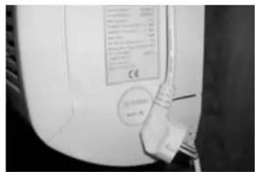
TYPEPLAATJE PLAQUE SIGNALÉTIQUE RATING LABEL
| HW-9KE Model Serial number | 2.7 kW 9000 BTU/h Cooling capacity | 2.8 kW 9500 BTU/h Heating capacity | |
| 230 V 50 Hz 1 Ph Power supply | 4.1/4.0 A max 5.4 A Rated current | 900 / 880 W Rated power consumed | |
| R410a Refrigerant | °C Thermostatic range | 460 m³/h18 Airflow | |
| 3.1/3.5 W/W EER / COP | ~38 dB(A).r Noise level | IP 20.8 kg Protection class | Net weight |
| Made in P.R.C. | www.amcorgroup.com NL-1422 AL UITHOORN | ||
| HW-9KE Model Serial number | 2.7 kW 9000 BTU/h Cooling capacity | 2.8 kW 9500 BTU/h Heating capacity | |
| 230 V 50 Hz 1 Ph Power supply | 2.4 / 4.0 MPa Pressure range Suction / Discharge | ||
| R410a Refrigerant | 740 g Refrigerant load | 10-40 °C Operatingrange | |
| 3.1/3.5 W/W EER / COP | ~52 dB(A).r Noise level | IP 24 Protection class | 31 kg Net weight |
| Made in P.R.C. | www.amcorgroup.com NL-1422 AL UITHOORN | ||
| Model Serial | INDOOR UNIT See barcode number | 3.5 kW 12000 BTU/h Cooling capacity | 3.6 kW 12300 BTU/h Heating capacity | ||
| 230 V 50 Hz 1 Ph Power supply | 5.7/6.0 A max 7.6 A Rated current | 1245 / 1300 W Rated power consumed | |||
| R410a Refrigerant | °C Thermostatic range | 500 m³/h18 Airflow | |||
| 3.1/3.0 W/W EER / COP | ~38 dB(A).r Noise level | IP 20 Protection class | 10 kg Net weight | ||
| Made in P.R.C. | NLC-1422 AL UITHOORN | ||||
| HW- 12KE Model Serial | OUTDOOR UNIT See barcode number | 3.5 kW 12000 BTU/h Cooling capacity | 3.6 kW 12300 BTU/h Heating capacity | ||
| 230 V 50 Hz 1 Ph Power supply | 2.4 / 4.0 MPa Pressure range Suction / Discharge | ||||
| R410a Refrigerant | 1050 g Refrigerant load | 10-40°C Operatingrange | |||
| 3.1/3.5 W/W EER / COP | ~53 dB(A).r Noise level | IP 24 Protection class | 38 kg Net weight | ||
| Made in P.R.C. | www.amcorgroup.com NL-1422 AL UITHOORN | ||||
Les données techniques peuvent etre modifiees sans preavis. Data are subject to change without notification, they are not legally binding.
AMCOR
Hong Kong
Amcor Ltd
Suite 2007, Tower 6, The Gateway,
Harbour City, 9 Canton Road,
Tsim Sha Tsui, Kowloon,
Hong Kong
Tel: +852 2997 6865
Fax:+85229976091
Email: amcorhk@amcorgroup.com
United Kingdom
Amcor Ltd
Ryan Drive, West Cross Centre,
Great West Road, Brentford,
Middlesex, TW8 gER,
United Kingdom
Tel:+442085604141
Fax:+4420823288141
Email: amcoruk@amcorgroup.com
USA
Amcor Inc.
685A Gotham Parkway, Carlstadt,
NewJersey 07072
United States of America
Tel: +1 201 460 8100
Fax:+12014609481
Email: amcorusa@amcorgroup.com
The Netherlands
Amcor B.V.
Anton Philipsweg 9-11
1422 AL Uithoorn,
The Netherlands
Tel: +31 297 560 079
Fax:+31297523062
Email: amcorex@amcorgroup.com
Israel
Amcor International Ltd
3 Sapir Street, Herzelia Pituach,
46733, Israel
Tel:+97299515351
Fax:+972 9 958 5650
Email: amcoril@amcorgroup.com
Singapore
Amcor Investments (Singapore) Pte Ltd
545 Orchard Road,
13-02, Far East Shopping Centre,
Singapore 238882
Tel: +65 6297 9881
Fax:+6562978891
Email: amcorsg@amcorgroup.com
China
Shan Xia Industrial Development Zone,
Heng Li Town, Dongguan City,
Guangdong Province, China
Plant One - Amcor (China) Ltd
Tel: +86 769 8372 1090
Fax:+8676983721790
Email: amcorcn@amcorgroup.com
Plant Two - Amcor Appliances Ltd
Tel: +86 769 8372 1970
Fax:+8676983721790
Email: amcorappl@amcorgroup.com