
DG3000C - Generator DEWALT - Free user manual and instructions
Find the device manual for free DG3000C DEWALT in PDF.

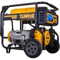
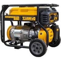
| Product Type | Portable Generator |
| Brand | DeWALT |
| Model | DG3000C |
| Maximum Output Power (AC) | 3 000 watts |
| Rated Output Power (AC) | 2 920 watts |
| Rated Current | 20 A |
| Output Voltage | 120 V |
| Alternator Type | Brushless, Double Lamination |
| Engine | DW168F-2F, 6.5 HP (gross), 196 cc |
| Fuel Tank Capacity | 12.5 L (3.3 US gallons) |
| Recommended Fuel | Unleaded gasoline, octane rating ≥ 86 |
| Engine Oil Type | Consult engine manual |
| Low Oil Level Sensor | Yes (automatic engine shutdown) |
| Starting System | Recoil (manual) |
| Power Outlets | 1 x dual GFCI 120V 20A, 1 x rotation lock 120V 20A (GFCI protected) |
| Circuit Breakers | Main circuit breaker + thermal circuit breakers on outlets |
| Dimensions (L x W x H) | 59.9 x 49.0 x 52.1 cm |
| Dry Weight | 53.5 kg |
| Additional Features | Voltage selector switch (120 V mode), idle control, battery pack port (electric start not included) |
| Noise Level | Not specified in the manual |
Frequently Asked Questions - DG3000C DEWALT
User questions about DG3000C DEWALT
0 question about this device. Answer the ones you know or ask your own.
Ask a new question about this device
Download the instructions for your Generator in PDF format for free! Find your manual DG3000C - DEWALT and take your electronic device back in hand. On this page are published all the documents necessary for the use of your device. DG3000C by DEWALT.
USER MANUAL DG3000C DEWALT
If you have questions or comments, contact us.
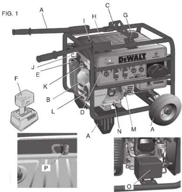
Generator with Electric Start DG4400B, DG4400BC, DG6300B, DG6300BC, DG7000B, DG7000BC
Généatrice DG3000, DG3000C
A.Wheel and handle kit (DG4400B, DG4400BC, DG6300B, DG6300BC, DG7000B, DG7000BC)
B. DEWALT engine
C. Lifting hook (included in A)
(DG4400B, DG4400BC, DG6300B, DG6300BC, DG7000B, DG7000BC)
D. Control panel, see Fig. 2 for individual model's control panel
E. Air filter
F. 18V DEWALT battery pack and charger (DG4400B, DG4400BC, DG6300B, DG6300BC, DG7000B, DG7000BC)
G. Fuel cap
H. Fuel tank
I. Fuel gauge
J. Choke control
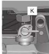
K. Fuel shut-off valve
L. recoil pull starter
M. Oil fill/dipstick
N. Oil drain plug
O. Carbon canister (if equipped)
P. Roll over valve (if equipped)
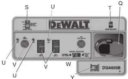
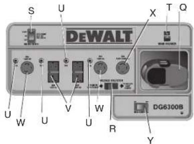
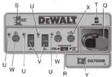
Control Panel Layouts
Q. Battery pack receptacle
(show with battery pack)
R. Voltage selector switch
S. Engine switch
T. Main breaker
U. Receptacle thermal circuit breakers
V. GFCI duplex receptacles (120V)
W. Twistlock receptacles (120V)
X. Twistlock receptacles (120V/240V)
Y. Idle control switch

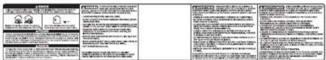
Definitions: Safety Guidelines
The definitions below describe the level of severity for each signal word. Please read the manual and pay attention to these symbols.
ADANGER: Indicates an imminently hazardous situation which, if not avoided, will result in death or serious injury.
WARNING: Indicates a potentially hazardous situation which, if not avoided, could result in death or serious injury.
CAUTION: Indicates a potentially hazardous situation which, if not avoided, may result in minor or moderate injury.
NOTICE: Indicates a practice not related to personal injury which, if not avoided, may result in property damage.
IF YOU HAVE ANY QUESTIONS OR COMMENTS ABOUT THIS OR ANY DEWALT TOOL, CALL US TOLL FREE AT: 1-800-4-DEWALT (1-800-433-9258)
Important Safety Instructions
ADANGER: Carbon Monoxide. Using an engine indoors can kill you in minutes. Engine exhaust contains high levels of carbon monoxide (CO), a poisonous gas you cannot see or smell. You may be breathing CO even if you do not smell engine exhaust.
WARNING: This product and its exhaust contain chemicals known to the State of California to cause cancer, and birth defects or other reproductive harm.
- NEVER use an engine inside homes, garages, crawlspaces or other partly enclosed areas. Deadly levels of carbon monoxide can build up in these areas. Using a fan or opening windows and doors does NOT supply enough fresh air.
-
ONLY use outdoors and far away from open windows, doors and vents. These openings can pull in engine exhaust.
-
Even when the engine is used correctly, CO may leak into your home. ALWAYS use a battery-powered or battery backup CO alarm in the home. Read and follow all directions for CO alarm before using. If you start to feel sick, dizzy or weak at anytime, move to fresh air immediately. See a doctor. You could have carbon monoxide poisoning.
WARNING: Do not operate this unit until you read and understand this instruction manual and the engine instruction manual for safety, operation and maintenance instructions.
IMPORTANT: These products are equipped with spark-arresting mufflers. It is legally required in the state of California. It is a violation of California statutes section 130050 and/or sec tions 4442 and 4443 of the California Public Re sourc es Code, unless the engine is equipped with a spark arrester, as defined in section 4442, and maintained in ef fec five working order. Spark arresters are also required on some U.S. For est Service land and may also be legally required under other statutes and or di nanc es.
SAVE THESE INSTRUCTIONS

ADANGER: RISK OF ELECTROCUTION AND FIRE
- Back feeding electricity through a building's electrical system to the outside utility feed lines could endanger repair persons attempting to restore service.
Never backfeed electricity through a structure's electrical system.
- Attempting to connect to the incoming utility service could result in electrocution.
- Restoration of electrical service while the generator is connected to the incoming utility could result in a fire or serious damage if a double throw transfer switch is not installed.
- Failure to use a double throw transfer switch when connecting to a structure's electrical system can damage appliances and WILL VOID the manufacturer's warranty.
Water can conduct electricity! Water which comes in contact with electrically charged components can transmit electricity to the frame and other surfaces, resulting in electrical shock to anyone contacting them. -
Contact with worn or damaged extension cords could result in electrocution.
Use of undersize extension cord(s) could result in overheating of the wires or attached items, resulting in fire. -
To connect to a structure's electrical system in a safe manner, always have a double-throw transfer switch installed by a qualified electrician and in compliance with local ordinances. (When installing a double-throw transfer switch, a minimum of 10 gauge wiring must be used.)
- Operate generator in a clean, dry, well ventilated area. Make sure hands are dry before touching unit.
- Inspect extension cords before use and replace with new cord if required.
-
Use proper size (wire gauge) extension cord(s) for application; see Use of Extension Cords under Assembly.
-
Use of ungrounded extension cord(s) could prevent operation of circuit breakers and result in electrical shock.
- Accidental leakage of electrical current could charge conductive surfaces in contact with the generator.
- Exceeding the load capacity of the generator by attaching too many items, or items with very high load ratings to it could result in overheating of some items or their attachment wiring resulting in fire or electrical shock.
- Attempting to use the unit when it has been damaged, or when it is not functioning normally could result in fire or electrocution.
- Removal of guarding could expose electrically charged components and result in electrocution.
Always use an extension cord(s) having a grounding wire with an appropriate grounding plug. DO NOT use an ungrounded plug.
- Place generator on low conductivity surface such as a concrete slab. ALWAYS operate generator a minimum of 6^ (1.8 m) from any conductive surface.
See Operating Heavy Loads under Operation. Make sure that the summation of electrical loads for all attachments does not exceed the load rating of the generator.
- Do not operate generator with mechanical or electrical problem. Contact a DEWALT factory service center or a DEWALT authorized service center.
- Do not operate generator with protective guarding removed.
- Unattended operation of this product could result in personal injury or property damage. To reduce the risk of fire, do not allow the engine to operate unattended.
ADANGER: RISK OF EXPISSION OR FIRE! CAN HAPPEN HOW TO PREVENT IT
Spilled gas o line and it's vapors can be come ignited from sparks from smoking products, electrical arcing, exhaust, flame, gas es and hot engine components such as the muffler.
- Heat will expand fuel in the tank which could result in spillage and possi ble fire explosion.
Always remain in attendance with the engine when it is operating.
- Shut off en gine and allow it to cool before removing cap and adding fuel to the tank.
- Use care in filling tank to avoid spilling fuel. Make sure the cap is secure and move unit away from fueling area before starting en gine.
-
Keep maximum fuel level below the shoulders on the debris screen to allow for expansion.
-
Combustible materials which come into contact with hot generator parts can become ignited.
-
Improperly stored fuel could lead to accident tal ignition. Fuel im properly secured could get into the hands of children or other un qual i fied persons.
Engine speed has been factory set to provide safe operation. Tampering with the engine speed adjustment could result in overheating of attachments and could cause a fire. -
Add fuel outdoors in a well ventilated area. Make sure there are no sources of ignition, such as smoking products near refueling location.
- Operate generator in a clean, dry, well ventilated area a minimum of 48^ (1.2 m) from any building, object or wall. Do not operate unit indoors or in any confined area.
- Operate generator in an open area away from dry brush, weeds or other combustible materials.
- Store fuel in an OSHA-approved con tain er, in a se cure location away from work area.
- Never attempt to "speed-up" the engine to obtain more performance. Both the output voltage and frequency will be thrown out of standard by this practice, endangering attachments and the user.

DANGER RISK TO BREATHING (ASPHYxIATION) WHAT CAN HAPPEN HOW TO PREVENT IT
-
Breathing ex haust fumes can cause serious injury or death! Engine exhaust contains high levels of carbon monoxide (CO), a poisonous gas you cannot see or smell. You may be breathing CO even if you do not smell engine exhaust.
-
NEVER use an engine inside homes, garages, crawlspaces, or other partly enclosed areas. Deadly levels of carbon monoxide can build up in these areas. Using a fan or opening windows and doors DOES NOT supply enough fresh air.
Only use outdoors and far away from open windows, doors and vents. These openings can pull in engine exhaust. - Keep children, pets and others away from area of operation.
Always keep the exhaust pipe free of foreign objects.

ADANGER: RISK OF INJURY OR PROPERTY DAMAGE WHEN TRANSPORTING OR STORING WHAT CAN HAPPEN HOW TO PREVENT IT
Oil and fuel can leak or spill and could result in fire or breathing hazard; serious injury or death can result. Oil leaks will damage carpet, paint or other surfaces in vehicles or trailers.
- Never transport generator with fuel in the fuel system, fuel valve open or while generator is in operation.
Always place generator on a protective mat when transporting to protect against damage to vehicle from leaks. Remove generator from vehicle immediately upon arrival at your destination. Always keep generator level and never lie on its side. - Transport fuel only in an OSHA approved container.

WARNING: RISK OF HOT SURFACES
WHat Can HappEn HoW to prEVENT It
-
Touching exposed metal (muffler and other engine parts) can result in serious bums.
-
Never touch any exposed metal parts on generator during or immediately after operation. The generator will remain hot for several minutes after operation.
- Do not reach around protective shrouds or attempt maintenance until generator has been allowed to cool.

WARNING: RISK FROM MOVING PARTS
WHAT Can HappEn HoW to prEVENT It
The engine can start accidentally if the flywheel is turned by hand or moved by pulling on the pull starter.
Always disconnect the spark plug before performing maintenance.
- Moving parts such as the pulley, flywheel and belt can cause serious injury if they come into contact with you or your clothing.
-
Attempting to operate generator with damaged or missing parts or attempting to repair generator with protective shrouds removed can expose you to moving parts and can result in serious injury.
-
Never operate the generator with guards or covers which are damaged or removed.
- Keep your hair, clothing and gloves away from moving parts. Loose clothes, jewelry or long hair can be caught in moving parts.
Air vents may cover moving parts and should be avoided as well. - Any repairs required on this product should be performed by a DEWALT factory service center or a DEWALT authorized service center.

WARNING: RISK OF UNSAFE OPERATION
WHAT Can HappEn HoW to prEVENT It
-
Unsafe op er a tion of you gen erator could lead to se ri ou s in ju ry or death to you or others.
-
Review and understand all instructions and warnings in this manual.
- Be come far mil jar with the op er a tion and con trols of the generator. Know how to shut it off quickly.
- Keep operating area clear of all persons, pets and obstacles.
| • Keep chil dren away from the generator at all times. • Do not operate the generator when fatigued or under the influence of alcohol or drugs. Stay alert at all times. • Never defeat the safety fea- tures of this product. • Equip area of operation with a fire extinguisher. • Do not op er ate generator with missing, broken or un au tho- rized parts. • Never stand on the generator. |
| • Any gasoline operated house- hold generator can produce voltage variations causing damage to voltage sensitive appliances or could result in fire. • Always use a U.L. listed volt- age sensitive surge protector to connect voltage sensitive appliances (TV, computer, ste- reo, etc.). Failure to use a U.L. listed voltage surge protector will void the warranty on your generator. notice: A multiple outlet strip is not a surge pro- tector. Make sure you use an U.L. listed voltage surge pro- tector |
| • Serious injury can result attempting to lift too heavy an object. be lifted by one person. Obtain assistance from others before you try to move it. |
| SAVE THESE INSTRUCTIONS |
Important Safety Instructions for Battery Packs
DG4400B, DG4400BC, DG6300B, DG6300BC, DG7000B, DG7000BC
An 18V DEWALT battery pack is used to start these units using the electric start feature. When ordering replacement battery packs be sure to include catalog number and voltage: Extended Run Time battery packs deliver 25% more run-time than standard battery packs. Consult chart at the end of this manual for compatibility of chargers and battery packs.
notE: Your tool will accept either standard or Extended Run Time battery packs. However, be sure to select proper voltage.
The battery pack is not fully charged out of the carton. Before using the battery pack and charger, read the safety instructions below. Then follow charging procedures outlined.
READ ALL INSTRUCTIONS
- Do not incinerate the battery pack even if it is severely damaged or is completely worn out. The battery pack can explode in a fire.
- A small leakage of liquid from the battery pack cells may occur under extreme usage or temperature conditions. This does not indicate a failure.
However, if the outer seal is broken:
a. and the battery liquid gets on your skin, immediately wash with soap and water for several minutes.
b. and the battery liquid gets into your eyes, flush them with clean water for a minimum of 10 minutes and seek immediate medical attention. (Medical note: The liquid is 25 - 35% solution of potassium hydroxide.)
-
Charge the battery packs only in DEWALT chargers.
DO NOT splash or immerse in water or other liquids. -
Do not store or use the battery pack in locations where the temperature may reach or exceed 105^ (such as outside sheds or metal buildings in summer).
ADANGER: Electrocution hazard. Never attempt to open the battery pack for any reason. If battery pack case is cracked or damaged, do not insert into charger. Electric shock or electrocution may result. Damaged battery packs should be returned to service center for recycling.
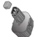
notE: Battery storage and carrying caps are provided.
for use whenever the battery is out of the generator or charger. Remove cap before placing battery in charger or generator.
WARNING: Fire hazard. Do not store or carry battery so that metal objects can contact exposed bat
tery terminals. For example, do not place battery in aprons, pockets, tool boxes, product kit boxes, drawers, etc., with loose nails, screws, keys, etc. without battery cap. Transporting batteries can possibly cause fires if the battery terminals inadvertently come in contact with conductive materials such as keys, coins, hand tools and the
like. The US Department of Transportation Hazardous Material Regulations (HMR) actually prohibit transporting batteries in commerce or on airplanes (i.e., packed in suitcases and carry-on luggage) UNLESS they are properly protected from short circuits. So when transporting individual batteries, make sure that the battery terminals are protected and well insulated from materials that could contact them and cause a short circuit.
The RBRC™ Seal
The RBRC^TM (Rechargeable Battery Recycling Corporation) Seal on the nickel cadmium and nickel metal hydride batteries (or battery packs) indicate that the costs to recycle these batteries (or battery packs) at the end of their useful life have already been paid by DEWALT. In some areas, it is illegal to place spent nickel cadmium and nickel metal hydride batteries in municipal solid waste stream and the RBRC program environmentally conscious alternative.

RBRC^TM in cooperation with DEWALT and other battery users, has established programs in the United States and Canada to facilitate the collection of spent nickel cadmium and nickel metal hydride batteries. Help protect our environment and conserve natural resources by returning the spent nickel cadmium and nickel metal hydride batteries to an authorized D EwALT service center or to your local retailer for recycling. You may also contact your local recycling center for information on where to drop off the spent battery.
RBRC^TM is a registered trademark of the Rechargeable Battery Recycling Corporation.
Important Safety Instructions for Battery Chargers
SAVE THESE INSTRUCTIONS: This manual contains important safety instructions for battery chargers.
Before using charger, read all instructions and cautionary markings on charger, battery pack, and product using battery pack.
ADANGER: Electrocution hazard. 120 volts are present at charging terminals. Do not probe with conductive objects.
WARNING: Shock hazard. Do not allow any liquid to get inside charger.
CAUTION: Burn hazard. To reduce the risk of injury, DEWALT nickel cadmium rechargeable batteries. Other types of batteries may burst causing personal injury and damage.
CAUTION: Under certain conditions, with the charger plugged in to the power supply, the exposed charging contacts inside the charger can be shorted by foreign material. Foreign materials of a conductive nature such as, but not limited to, steel wool, aluminum foil, or any buildup of metallic particles should be kept away from charger cavities. Always unplug the charger from the power supply when there is no battery pack in the cavity. Unplug charger before attempting to clean.
-
DO NOT attempt to charge the battery pack with any chargers other than the ones in this manual. The charger and battery pack are specifically designed to work together.
-
These chargers are not intended for any uses other than charging DEWALT rechargeable batteries. Any other uses may result in risk of fire, electric shock or electrocution.
- Do not allow charger to get wet.
DO NOT ABUSE CORD. Never carry charger by cord or yank to disconnect from receptacle. Pull by plug rather than cord when disconnecting charger. This will reduce risk of damage to electric plug and cord. Have damaged or worn power cord and strain relief replaced immediately.
Make sure that cord is located so that it will not be stepped on, tripped over, or otherwise subjected to damage or stress. - Do not use an extension cord unless it is absolutely necessary. Use of improper extension cord could result in risk of fire, electric shock, or electrocution.
An extension cord must have adequate wire size (AWG or American Wire Gauge) for safety. The smaller the gauge number of the wire, the greater the capacity of the cable, that is 16 gauge has more capacity than 18 gauge. When using more than one extension to make up the total length, be sure each individual extension contains at least the minimum wire size. If an extension cord is to be used outdoors it must be marked with the suffix "A" or "W" following the cord type designation. For example - SJTW-A to indicate it is acceptable for outdoor use.
Recommended Minimum Wire Size for Extension Cordstal Length of Cord
| 25 ft. | 50 ft. | 75 ft. | 100 ft. | 125 ft. | 150 ft. | 175 ft. |
| 7.6 m | 15.2 m | 22.9 m | 30.5 m | 38.1 m | 45.7 m | 53.3 m |
| Wire Size AWG | ||||||
| 18 | 18 | 16 | 16 | 14 | 14 | 12 |
-
Do not place any object on top of charger or place the charger on a soft surface that might block the ventilation slots and result in excessive internal heat. Place the charger in a position away from any heat source. The charger is ventilated through slots in the top and the bottom of the housing.
-
Do not operate charger with damaged cord or plug — have them replaced immediately.
- Do not operate charger if it has received a sharp blow, been dropped, or otherwise damaged in any way. Take it to an authorized service center.
- Do not disassemble charger; take it to an authorized service center when service or repair is required. Incorrect reassembly may result in a risk of electric shock, electrocution or fire.
- Disconnect the charger from the outlet before attempting any cleaning. This will reduce the risk of electric shock. Removing the battery pack will not reduce this risk.
NEVER attempt to connect 2 chargers together. - The charger is designed to operate on standard household electrical power (120 Volts). Do not attempt to use it on any other voltage. This does not apply to the vehicular charger.
SAVE THESE INSTRUCTIONS FOR FUTURE USE
Charging Procedure
DG4400B, DG4400BC, DG6300B.
DG6300BC, DG7000B, DG7000BC
ADANGER: Electrocution hazard. 120 volts are present at charging terminals. Do not probe with conductive objects.
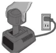
- Plug the charger into an appropriate outlet before inserting battery pack.
- Remove the caps from the battery pack and insert battery pack into the charger. The red (charging) light will blink continuously indicating that the charging process has started.
- The completion of charge will be indicated by the red light remaining ON continuously. The pack is fully charged and may be used at this time or left in the charger.
Using Automatic Tune-UpTM Mode
DG4400B, DG4400BC, DG6300B, DG6300BC, DG7000B, DG7000BC
The automatic Tune-Up™ Mode equalizes or balances the invidual cells in the battery pack allowing it to function at peak capacity. Battery packs should be tuned up weekly or after 10 charge/discharge cycles or whenever the pack no longer delivers the same amount of work. To use the Automatic Tune-Up™, place the battery pack in the charger and leave it for at least 8 hours.
Indicator Light Operation

Charge Indicators
DG4400B, DG4400BC, DG6300B, DG6300BC, DG7000B, DG7000BC
Some chargers are designed to detect certain problems that can arise with battery packs. Problems are indicated by the red light flashing at a fast rate. If this occurs, re-insert battery pack into the charger. If the problem persists, try a different battery pack to determine if the charger is OK. If the new pack charges correctly, then the original pack is defective and should be returned to a service center or other collection site for recycling. If the new battery pack elicits the same trouble indication as the original, have the charger tested at an authorized service center.
HOT/COLD PACK DELAY
Some chargers have a Hot/Cold Pack Delay feature: when the charger detects a battery that is hot, it automatically starts a Hot Pack Delay, suspending charging until the battery has cooled. After the battery has cooled, the charger automatically switches to the Pack Charging mode. This feature ensures maximum battery life. The red light flashes long, then short while in the Hot Pack Delay mode.
PROBLEM POWER LINE
Some chargers have a Problem Power Line indicator. When the charger is used with some portable power sources such as generators or sources that convert DC to AC, the charger may temporarily suspend operation, flashing the red light with two fast blinks followed by a pause. This indicates the power source is out of limits.
LEAVING THE BATTERY PACK IN THE CHARGER
The charger and battery pack can be left connected with the red light glowing indefinitely. The charger will keep the battery pack fresh and fully charged.
NOTE: A battery pack will slowly lose its charge when kept out of the charger. If the battery pack has not been kept on maintenance charge, it may need to be recharged before use. A battery pack may also slowly lose its charge if left in a charger that is not plugged into an appropriate AC source.
WEAK BATTERY PACKS: Chargers can also detect a weak battery. Such batteries are still usable but should not be expected to perform as much work. In such cases, about 10 seconds after battery insertion, the charger will beep rapidly 8 times to indicate a weak battery condition. The charger will then go on to charge the battery to the highest capacity possible.
Important Charging Notes
- Longest life and best performance can be obtained if the battery pack is charged when the air temperature is between 65^ and 75^ (18^ - 24^) . DO NOT charge the battery pack in an air tem
perature below +40^ (+4.5^) or above +105^ (+40.5^) . This is important and will prevent serious damage to the battery pack.
- The charger and battery pack may become warm to touch while charging. This is a normal condition, and does not indicate a problem. To facilitate the cooling of the battery pack after use, avoid placing the charger or battery pack in a warm environment such as in a metal shed, or an uninsulated trailer.
- If the battery pack does not charge properly:
a. Check current at receptacle by plugging in a lamp or other appliance
b. Check to see if receptacle is connected to a light switch which turns power off when you turn out the lights.
c. Move charger and battery pack to a location where the surrounding air temperature is approximately 65^ - 75^ (18^ - 24^)
d. If charging problems persist, take the tool, battery pack and charger to your local service center. - The battery pack should be recharged when it fails to produce sufficient power on jobs which were easily done previously. DO NOT CONTINUE to use under these conditions. Follow the charging procedure. You may also charge a partially used pack whenever you desire with no adverse effect on the battery pack.
- Under certain conditions, with the charger plugged into the power supply, the exposed charging contacts inside the charger can be shorted by foreign material. Foreign materials of a conductive nature such as, but not limited to, steel wool, aluminum foil, or any buildup of metallic particles should be kept away from charger cavities. Always unplug the charger from the power supply when there is no battery pack in the cavity. Unplug charger before attempting to clean.
- Do not freeze or immerse charger in water or any other liquid. WARNING: Shock hazard. Do not allow any liquid to get inside charger.
CAUTION: Never attempt to open the battery pack for any reason. If the plastic housing of the battery pack breaks or cracks, return to a service center for recycling.
Charging Portable Power Tool Batteries
WARNING: Condenser type chargers should not be used with portable generators. Irregular generator power could cause a condenser type charger to fail. DEWALT has produced condenser type chargers in the past. (DW9104 and DW9106). If you have any questions regarding the use of a DEWALT Charger with a generator, please call 1-800-4-DEWALT.
NOTE: Other battery charger manufacturers have and still produce condenser type chargers. Please contact manufacturer to see if it is safe to use chargers with portable generators.
Product Specifications
| Model DG3000 | DG3000C | DG4400B, DG4400BC |
| Alternator | ||
| Type Brushless, 2-Pole Brushless, 2-Pole | ||
| Excitation Condenser Condenser | ||
| Max AC Output (Watts) 3000 4400 | ||
| Rated AC Output (Watts) 2920 4180 | ||
| Rated Current (A) 20 A | 31.7/15.9 A | |
| Phase | Single | Single |
| Frequency | 60 | 60 |
| Engine | ||
| Model | DW168F-2F | DW177F-F |
| Horse Power (*Gross HP) | *6.5 | *9 |
| Displacement (CC) | 196 270 | |
| Fuel Tank Capacity (gal) | 3.3 (12.5 liters) | 4.6 (17.4 liters) |
| Recommended Fuel | See engine instruction manual | See engine instruction manual |
| Model DG3000 | DG3000C | DG4400B DG4400BC |
| Oil Capacity | See engine instruction manual | See engine instruction manual |
| Recommended Oil | See engine instruction manual | See engine instruction manual |
| Low Oil Shutdown | Yes | Yes |
| Starting system | Recoil | Recoil/Elec. Start |
| Receptacles | ||
| 120V 20 Amp GFCI Duplex | Yes (1) | Yes (2) |
| 120V 20 A Twist-Locking (NEMA L5-20R) + | Yes (1) | Yes (1) |
| 120V 30 A Twist-Locking (NEMA L5-30R) + | No | No |
| 120/240V 20 A Twist- Locking (NEMA L14-20R)+ | No | Yes (1) |
| 120/240V 30 A Twist- Locking (NEMA L14-30R)+ | No | No |
| General | ||
| Dimensions * (in./cm) (L x W x H) | (23.6 x 19.3 x 20.5/ 59.9 x 49.0 x 52.1 cm) | (28.0 x 21.7 x 21.5/ 71.1 x 55.1 x 54.6 cm) |
| Dry Weight* | 118 lbs. (53.5 kg) | 234 lbs. (106 kg) |
| • Dimensions do not include wheel kit. | ||
| * Gross horsepower (HP). This horsepower rating represents the maximum output under laboratory conditions at 3600 RPM in accordance with SAE (Society of Automotive Engineers) J1995 and should be used for comparison purposes only. Actual engine output will be lower and will vary depending on the application, speed and other variables including altitude and temperature. | ||
| + When using the 20A or 30A twist-locking receptacle, you must connect through a GFCI protected spider box or use an in-line GFCI adapter. | ||
| Model DG6300B | DG6300BC | DG7000B DG7000BC |
| Alternator | ||
| Type Brushless, 2-Pole Brushless, 2-Pole | ||
| Excitation Condenser Condenser | ||
| Max AC Output (Watts) 6300 7000 | ||
| Rated AC Output (Watts) 5950 6550 | ||
| Rated Current (A) 49.6/24.8 | 54.6/27.3 | |
| Phase Single Single | ||
| Frequency (Hz) 60 60 | ||
| Engine | ||
| Model | DW188F | DW188F |
| Horse Power (*Gross HP) *13 | *13 | |
| Displacement (CC) | 389 | 389 |
| Fuel Tank Capacity (gal) | 4.6 (17.4 liters) | 4.6 (17.4 liters) |
| Recommended Fuel | See engine instruction manual | See engine instruction manual |
| Oil Capacity | See engine instruction manual | See engine instruction manual |
| Recommended Oil | See engine instruction manual | See engine instruction manual |
| Low Oil Shutdown | Yes | Yes |
| Starting system | Recoil/Elec. Start | Recoil/Elec. Start |
| Receptacles | ||
| 120V 20 A GFCI Duplex | Yes (2) | Yes (2) |
| 120V 20 A Twist-Locking (NEMA L5-20R) + | No | No |
| 120V 30 A Twist-Locking (NEMA L5-30R) + | Yes (2) | Yes (2) |
| 120/240V 20 A Twist- Locking (NEMA L14-20R)+ | No | No |
| 120/240V 30 A Twist- Locking (NEMA L14-30R)+ | Yes (1) | Yes (1) |
| General | ||
| Dimensions • (in.) (LxWxH) | (28 x 21.7 x 21.5/71,1 x 55,1 x 54,6 cm) | (28 x 21.7 x 21.5/71,1 x 55,1 x 54,6 cm) |
| Dry Weight • | 246 lbs. (111.5 kg) | 261.5 lb (118.5 kg) |
| • Dimensions do not include wheel kit. | ||
| * Gross horsepower (HP). This horsepower rating represents the maximum output under laboratory conditions at 3600 RPM in accordance with SAE (Society of Automotive Engineers) J1995 and should be used for comparison purposes only. Actual engine output will be lower and will vary depending on the application, speed and other variables including altitude and temperature. | ||
| + When using the 20A or 30A twist-locking receptacle, you must connect through a GFCI protected spider box or use an in-line GFCI adapter. | ||
ASSEMBLY
Grounding the Generator
A grounding lug (VV) is supplied with the generator for use when required by local electrical ordinances. Refer to article 250 of the National Electrical Code to clarify any needed grounding information. Your local electric company or a certified electrician should be able to help you with this information.
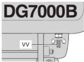
NOTE: Your engine is already grounded to the frame by a grounding strap.
Use of Extension Cords
WARNING: Use only grounded extension cords. Use only three wire or double-insulated power tools.
Only use grounded extension cords that are rated for outdoor use and equipment with a third-wire ground. When using the 20A or 30A twist-locking receptacle, you must connect through a GFCI protected spider box or use an in-line GFCI adapter.
When a long extension cord is used to connect an appliance or tool to the generator, a voltage drop occurs. The longer the cord, the greater the voltage drop. This results in less voltage being supplied to the appliance or tool and increases the amount of current (amp) draw or reduces performance. A heavier cord with a larger wire size will reduce the voltage drop. Be sure to choose a cord that will supply enough voltage to operate your tool or appliance. The tables indicate appropriate gauge for extension cords and the voltage drop caused by the use of extension cords, given different electrical loads.
CAUTION: Operating equipment at low voltage can cause it to overheat. Using an excessively long extension cord can cause the cord to overheat.
WARNING: Keep electrical cords in good condition. Do not use worn, bare or frayed cords because they can cause electrical shock.
| MINIMUM GAUGE FOR EXTENSION CORD SETS | ||||
| Volts Total Length of Cord in Feet | ||||
| 120V 0-25 | (0-6.7 m) | 26-50 | 51-100 | 101-150 |
| (7.9-15.2 m) | (15.5-30.5 m) | (30.8-45.7 m) | ||
| 240V 0-50 | (0-15.2 m) | 51-100 | 101-200 | 201-300 |
| (15.5-30.5 m) | (30.8-60.9 m) | (61.2-91.4 m) | ||
| Ampere Rating | AWG | |||
| 0-10 16 | 16 14 14 | |||
| 10-13 15 | 16 14 12 | |||
| 13-16 14 | 14 12 12 | |||
| 16-25 12 | 12 12 10 | |||
| 25-30 10 | 10 10 Not | Recommended | ||
| Extension Cord Length | Amp Load | Voltage Drop | |||
| 16 AWG | 14 AWG | 12 AWG | 10 AWG | ||
| 25 Foot 7.6 m | 10 A | 2.0 | 1.3 | 0.8 | 0.5 |
| 15 A | 3.0 | 1.9 | 1.2 | 0.8 | |
| 20 A | 4.0 | 2.5 | 1.6 | 1.1 | |
| 30 A | 6.0 | 3.8 | 2.3 | 1.6 | |
| 50 Foot 15.2 m | 10 A | 4.0 | 2.5 | 1.6 | 1.1 |
| 15 A | 6.0 | 3.8 | 2.3 | 1.6 | |
| 20 A | 8.0 | 5.0 | 3.1 | 2.1 | |
| 30 A | 12.0 | 7.5 | 4.7 | 3.2 | |
| 100 Foot 30.5 m | 10 A | 8.0 | 5.0 | 3.1 | 2.1 |
| 15 A | 12.0 | 7.5 | 4.7 | 3.2 | |
| 20 A | 16.0 | 10.0 | 6.2 | 4.2 | |
| 30 A | 24.0 | 15.0 | 9.3 | 6.3 | |
| 150 Foot 45.7 m | 10 A | 12.0 | 7.5 | 4.7 | 3.2 |
| 15 A | 18.0 | 11.3 | 7.0 | 4.7 | |
| 20 A | 24.0 | 15.0 | 9.3 | 6.3 | |
| 30 A | 36.0 | 22.5 | 14.0 | 9.5 | |
Accessories Assembly
DG4400B, DG4400BC, DG6300B, DG6300BC, DG7000B, DG7000BC
Accessories available for generators include wheels (A), handles (A) and lifting hook (C). NOTE: Two people are needed for these installations. Install the wheel kit before adding gasoline or engine oil to prevent damage to the engine. If accessories are being installed after running the generator, make sure the gas tank is empty, the fuel shut-off valve is turned to the OFF position (horizontal to the ground) and the oil is drained from the engine. FIG. 3 shows the accessory kit contents.
notE: After approximately 20 hours of operation, accessory bolts may loosen. Tighten them as needed.
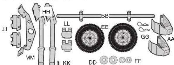
Wheel Kit Assembly
CAUTION: Risk from Lifting. The generator is too heavy to be lifted by one person. Obtain assistance from others before lifting.
- Carefully tilt the generator so it rests on the engine side.
- Install the two stands (AA) at the lower chassis. Install the wheel axle (BB) to the upper chassis. Use the bolts (KK) for these two steps.
- Insert the two larger washers (DD) on each end of the axle. Slide the tires (EE) on the axle.
- Insert the two small washers (FF) on the outside of the wheels and secure with cotter pins (GG).
- Place the generator upright so it is resting on the wheels and stands.
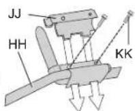
Handle Kit Assembly
- Install handles on the engine side of the generator by placing the handle assembly (HH) on the top horizontal bars and then inserting the bottom clamp (JJ).
- Use the bolts (KK) to secure the bottom clamp to the top clamp.
- Tighten the bolts until the assembly is snug or until the gap between the top and bottom clamps is closed.
Lifting Hook Assembly
- Insert the lifting hook (MM) under the two horizontal bars and position it as shown.
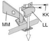
- Place the top clamp (LL) over the horizontal bars and fasten to the lifting hook using the bolts (KK).
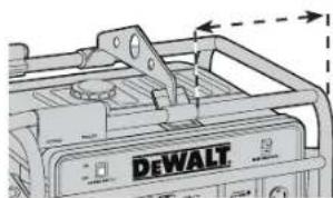
- Position the lifting hook as shown and adjust to the correct location per model:
DG4400B, DG4400BC, DG6300B, DG6300BC - Place the edge of the lifting hook 12.5" (31.8 cm) from the edge of the frame as shown.
DG7000B, DG7000BC - Place the edge of the lifting hook 12.25" (31.1 cm) from the edge of the frame as shown.
- Tighten the bolts firmly until the gap between the top clamp and the lifting hook is closed.
Chargers
DG4400B, DG4400BC, DG6300B, DG6300BC, DG7000B, DG7000BC
The 18V battery pack uses an 18V D EWALT Charger (included). The battery can also be charged in D EWALT 1 Hour Chargers, 15 Minute Chargers or Vehicular 12V charger. Be sure to read all safety instructions before using your charger. Consult the chart at the end of this manual for compatibility of chargers and battery packs.
Add Engine Oil and Fuel
IMPORTANT! The engine is NOT filled with oil from the factory. Oil must be added to the engine before operating or damage to engine may occur.
ADD ENGINE OIL
See engine's instruction manual for correct procedure.
ADD FUEL TO ENGINE (FIG. 1)
WARNING: Risk of explosion or fire. Gasoline vapor is highly flammable. Refuel outdoors preferably or only in well-ventilated areas. Do not refuel or check gasoline level while the engine is running. Do not store, spill or use gasoline near an open flame, a source of sparks (such as welding), or near operating electrical equipment. Do not smoke when filling fuel tank.
-
Remove fuel cap (G).
-
Add fresh, clean, regular unleaded gasoline with a minimum of 86 octane to the fuel tank (H). NOTE: Do not mix oil with gasoline.
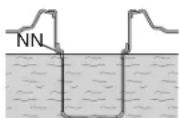
WARNING: Never fill fuel tank completely. Do not fill above the shoulders on the debris screen (NN) as shown to provide space for fuel expansion. Wipe any fuel spillage from engine and equipment before starting engine.
- Replace the fuel cap on the tank. Turn the cap clockwise until it stops.
FEATURES (FIG. 1, 2)
ENGINE SWITCH
The engine switch (S) must be in the ON position to start. To stop the engine, place switch in the OFF position. See Starting and Stopping under Operation for complete starting and stopping instructions.
ELECTRIC START
DG4400B, DG4400BC, DG6300B, DG6300BC, DG7000B, DG7000BC
On these generators, the engine switch (S) can be placed in three positions; OFF, ON and START. See Starting under Operation for complete starting instructions.
18V BATTERY PACK AND CHARGER
The DG4400B, DG4400BC, DG6300B, DG6300BC, DG7000B and DG7000BC models have an electric start feature that uses an 18V battery pack (F) to start the engine. The battery pack is charged by using the charger. See Charger Procedure under Assembly for charging procedure.
MAIN BREAKER
The main breaker (T) protects the alternator. Overloading the generator will trip the main circuit breaker. A short circuit in an electrical device being powered can also trip the main circuit breaker. If the main breaker trips:
- Disconnect the electrical loads from all receptacles.
- Place the main circuit breaker (T) in the OFF position and then back into the ON position to reset.
IMPORTANT: If the main breaker turns to the OFF position when no electrical loads are connected, contact a DEWALT factory service center or a DEWALT authorized service center.
RECEPTACLE THERMAL CIRCUIT BREAKERS
The receptacle thermal circuit breakers protect the receptacles. Overloading the generator will trip the thermal circuit breaker (U). If a thermal circuit breaker moves to the tripped position as shown:
- Disconnect the electrical load from the receptacle.
- Allow the circuit breaker to cool.
- Push the thermal circuit breaker to reset. If thermal circuit breaker will not reset, contact a DEWALT factory service center or a DEWALT authorized service center.
NOTE: The 120/240V twist-locking receptacle does not have a thermal circuit break er. The receptacle is protected by the main breaker. High ambient temperatures can cause thermal breakers to trip.
GFCI DUPLEX RECEPTACLES (120V)
All 20A convenience receptacles are GFCI (V) protected. The GFCI protects you against hazardous electrical shock caused body becomes a path through which electricity travels to the ground. This could happen when you touch a cord of an appliance that is "live" through faulty mechanism, dampness or worn insulation, etc. The GFCI shuts off the power to the recep tacle when it senses small imbalances caused by current leakage to the ground.
ACAUTION: Each GFCI should be tested for proper operation every time the generator is used, see Test GFCI under Maintenance.
TWISTLOCK RECEPTACLES (120V)
NOTE: (DG4400B, DG4400BC, DG6300B, DG6300BC, DG7000B, DG7000BC) The 20A and 30A twistlock receptacles are not protected by the GFCI. Use a GFCI protected spider box or GFCI adapter to connect loads to the 20A and 30A twistlock receptacles.
NOTE: (DG3000, DG3000C) The 20A twistlock receptacle is protected by the GFCI.
VOLTAGE SELECTOR SWITCH
DG4400B, DG4400BC, DG6300B, DG6300BC, DG7000B, DG7000BC
This switch (R) allows the generator to operate in either single voltage (120V) or dual voltage (120/240V) mode. When placed in the 120V position it allows you to receive the full capacity of the generator by using all the receptacles. When placed in the 120/240 position, you will only be able to receive half the available watts when using the 120 volt receptacles and the full available watts when using the 240V 4-prong twist-lock receptacle.
NOTE: Do not move the voltage selector switch (R) while powering electrical devices. Disconnect all electrical loads before moving the switch. Failure to disconnect electrical loads could damage the switch.
IDLE CONTROL SWITCH
DG4400B, DG4400BC, DG6300B, DG6300BC, DG7000B, DG7000BC
The idle control switch (Y) automatically reduces engine speed after all electrical loads attached to the generator have been turned off. The engine automatically returns to full speed when an electrical load is turned back on. Using this feature is recommended while the generator is running to minimize fuel consumption.
To use the idle control feature:
- Place the idle control switch (Y) in the ON position. NOTE: The idle control switch must be in the OFF position when starting the engine.
Using the idle control switch IS NOT recommend on large motors (refrigerators, freezers, etc) or voltage sensitive electronic equipment (computers, televisions, etc). For these applications
- Place the idle control switch in the OFF position.
LOW OIL PROTECTION
Low oil shutdown is a device designed to protect the engine from damage in the event the oil level in the crankcase is low. If while the engine is running, the oil gets low, it will automatically shut itself down and will not restart until the oil is added. If the oil is low before start-up, the generator will not start until oil is added. NOTE: The low oil shutdown mechanism is very sensitive. You must fil the engine to the full mark on the dipstick.
OPERATION
Pre-Start Checklist (Fig. 2)
WARNING: Do not operate this unit until you read and understand this instruction manual and the engine instruction manual for safety, operation and maintenance instructions.
CAUTION: Always check engine oil level before every start. Running engine low of oil or out of oil could result in serious damage to the engine.
Follow the steps listed below before starting generator:
- Check engine oil. Refer to the engine instruction manual for correct grade and quantity of oil.
- Check fuel level, fill as required. See Add Engine Oil and Fuel under Assembly.
- Make sure generator is grounded in accordance with local requirements. See Grounding the Generator under Assembly.
- All electrical loads MUST be disconnected and main breaker (T) in the OFF position.
- (DG4400B, DG4400BC, DG6300B, DG6300BC, DG7000B, DG7000BC) The idle control switch (Y) MUST be in the OFF position.
CAUTION: Engine speed has been factory set to provide safe operation. Tampering with the engine speed adjustment could result in overheating of attachments and could cause a fire. Never attempt
to "speed-up" the engine to obtain more performance. Both the output voltage and frequency will be thrown out of standard by this practice, endangering attachments and the user. Tampering may cause damage to the generator and voids the warranty.
CAUTION: Unplug any load from the generator before starting to prevent permanent damage to any appliances.
- Test the GFCI outlets (V), see Test GFCI under Maintenance.
Starting Generator -Recoil Start (Fig.1,2)
WARNING: Do not operate this unit until you read and understand this instruction manual and the engine instruction manual for safety, operation and maintenance instructions.
- Disconnect all electrical loads from the generator and place the main circuit breaker (T) in the OFF position.
- (DG4400B, DG4400BC, DG6300B, DG6300BC, DG7000B, DG7000BC) Place the idle control switch (Y) in the OFF position.
- Turn the fuel shut-off valve (K) on the gas tank to the vertical (OPEN) position as shown.
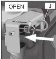
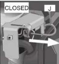
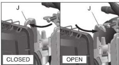
- If the engine is cold, move the choke (J) to the CLOSED position shown. If the engine is hot, move the choke to OPEN position.
OR
-
Turn engine switch (S) to the ON position.
-
Pull the starter grip (L) slowly until you feel compression then pull briskly.
NOTE: Do not allow the starter grip to snap back. Return it slowly by hand.
NOTE: If the oil level in the engine is low, the engine will not start. If the engine does not start, check the oil level and add oil as needed.
NOTE: To ensure maximum oil lubrication, place the generator on a level surface.
-
As the engine warms up, move the choke to the OPEN position.
-
Allow the engine to warm up for five minutes. Then place main breaker (T) in the ON position. Connect electrical loads, see Connecting Electrical Loads under Operation.
Starting the Generator - Electric Start (Fig. 1, 2)
DG4400B, DG4400BC, DG6300B, DG6300BC, DG7000B, DG7000BC
WARNING: Do not operate this unit until you read and understand this instruction manual and the engine instruction manual for safety, operation and maintenance instructions.
-
Follow steps 1 through 5 under Starting the Generator - Recoil Start.
-
Remove cap from 18V battery pack (F) and plug battery power pack into battery receptacle (Q). NOTE: Make sure your battery pack is fully charged.
-
Place engine switch (S) in the START position and hold until the engine starts.
NOTE: Do not hold the switch in the start position for more than 5 seconds. If the engine does not start, wait 10 seconds before retrying. Failure to follow these instructions may result in damage to the starter motor due to overheating.
- When the engine starts, release the engine switch allowing it to return to the ON position.
NOTE: Do not turn the engine switch to the START position while the gen erator is running.
-
As the engine warms up, move the choke (J) to the OPEN position as shown.
-
Allow the engine to warm up for five minutes. Then place the main breaker (T) in the ON position. Connect electrical loads, see Connecting Electrical Loads under Operation.
Stopping the Generator (Fig. 1, 2)
To stop the engine in an emergency, move the engine switch (S) to the OFF position.
To Stop the Generator in Normal Use:
- Disconnect all electrical loads attached to the generator.
- Move the engine switch (S) in the OFF position.
- Turn the fuel shut-off valve (K) on the gas tank to the horizontal (CLOSED) position as shown.
Connecting Electrical Loads
- Allow the engine to warm up for five minutes. Then place the main breaker (T) in the ON position.
Connect loads in the following manner to prevent damage to equipment: - Connect inductive load equipment first. Inductive loads consist of refrigerators, freezers, water pumps, air conditioners or small hand tools. Connect the items that require the most wattage first.
- Connect the lights next.
- Voltage sensitive equipment should be the last equipment connected to the generator. Plug voltage sensitive appliances such as TV's, VCR's, microwaves, ovens, computers, and cordless telephones into a UL listed voltage surge protector, then connect the UL listed voltage surge protector to the generator.
WARNING: Failure to connect and operate equipment in this sequence can cause damage to equipment and will void the warranty on your generator.
Operating Heavy Loads
Maximum output for short periods.
| DeWALT Model | DG3000, DG3000C | DG4400B, DG4400BC | DG6300B, DG6300BC | DG7000B, DG7000BC |
| Maximum Output | 3000 Watts | 400 Watts | 6300 Watts | 7000 Watts |
For continuous operation do not exceed the continuous rated output.
| DeWALT Model | DG3000, DG3000C | DG4400B, DG4400BC | DG6300B, DG6300BC | DG7000B, DG7000BC |
| Continuous Rated Output | 2920 Watts 4180 Watts 5950 Watts 6550 Watts | |||
DO NOT exceed the current limit specified on the control panel for any receptacle.
High Altitude Operating
At high altitude, the standard carburetor air-fuel mixture will be too rich. Performance will decrease and fuel consumption will increase. A very rich mixture will also foul the spark plug and cause hard starting.
High altitude performance can be improved by specific modifications to the carburetor. If you always operate your engine at altitudes above
1,524 meters (5,000 feet), have your authorized service center perform a carburetor modification.
Even with a carburetor modification, engine horsepower will decrease about 3.5% for each 300 meter (1,000 foot) increase in altitude. The effect of altitude on horsepower will be greater than this if no carburetor modification is made. A decrease in engine horsepower will decrease the power output of the generator.
NOTE: When the carburetor has been modified for high altitude operation, the air-fuel mixture will be too lean for low altitude use. If the generator is used at low altitudes after a carburetor modification, the carburetor may cause the engine to overheat and result in serious engine damage. For use at low altitudes, have your authorized service center return the carburetor to original factory specifications.
High and Low Temperature Operation
Air temperature affects generator output. Output drops 1% for each 10^ temperature rise above 60^ . Very low temperature may cause the engine to be hard to start.
Raising or Suspendng Generator
DG4400B, DG4400BC, DG6300B
DG6300BC, DG7000B, DG7000BC
WARNING: Failure to properly connect lifting cables, chains or straps can cause property damage, serious injury or death, and void the manufacturer's warranty.
WARNING: Always use cables, chains or straps rated at 2000 lbs. working load or more to raise or suspend generator.
WARNING: Never operate generator while suspended. This could cause property damage, serious injury or death.
WARNING: DO NOT suspend objects other than generator from lifting hook.
WARNING: Make sure all fasteners in frame and lifting hook are tight.
Route cable, chain or strap through lifting hook (C) as shown. ALWAYS use lifting hook when raising or suspending generator.
notE: Make sure the generator is in a level position before raising or suspending to prevent damage.
MAINTENANCE
Importance of Maintenance
Good maintenance is essential for safe, economical and trouble-free operation. It will also help reduce air pollution.
WARNING: Improper maintenance or failure to correct a problem before operation can cause malfunction, serious injury or death. Always follow the inspection and maintenance recommendation and schedules in this manual.
The following pages include a maintenance schedule, routine inspection procedures and simple maintenance procedures using basic hand tools to help you properly care for your generator. If you are not comfortable with any maintenance procedure, contact a D EWALT factory service center or a D EWALT authorized service center.
Maintenance, replacement or repair of the emission control devices and system may be performed by any engine repair establishment or individual using parts that are certified to EPA standards.
Maintenance Safety
WARNING: Do not operate this unit until you read and understand this instruction manual and the engine instruction manual for safety, operation and maintenance instructions..
SafEtY prECautionS
WARNING: Make sure the engine is off before beginning any maintenance or repairs. This will eliminate several potential hazards, including:
- carbon monoxide poisoning from engine exhaust. Be sure there is adequate ventilation whenever you operate the engine.
- burns from hot parts. Let the engine and exhaust system cool before you touch it to prevent burns.
- injury from moving parts. Wear appropriate clothing, tie long hair, and stay alert around the generator to prevent injury from moving parts.
WARNING: To reduce the possibility of fire or explosion, be careful when working around gasoline. Use only a nonflammable solvent, not gasoline, to clean parts. Keep smoking products, sparks and flames away from all fuel related parts.
Read all instructions before beginning and make sure you have the tools and skills required. A DEWALT factory service center or a DEWALT authorized service center knows your generator best and is fully equipped to do maintenance and repair. To ensure the best quality and reliability, use only new genuine parts or their equivalents for repair or replacement.
General Maintenance
WARNING: Contact with a hot engine or exhaust system can cause serious burns or fires. Let the engine and muffler cool before storing the generator.
notE: All generators contain maintenance parts (e.g. oil, filters, etc.) that are periodically replaced. These used parts may contain substances that are regulated and must be disposed of in accordance with local, state, provincial and federal laws and regulations.
NOTE: Take note of the positions and locations of parts during disassembly to make reassembly easier.
NOTE: Any service operations not included in this section should be performed by a DEWALT factory service center or a DEWALT authorized service center.
The following procedures must be followed when maintenance or service is performed on the generator.
Maintenance Chart
| Procedure | Daily | 50 hours (whichever comes first) | 100 hours | 150 hours or monthly (whichever comes first) | 500 Hours |
| Test GFCI | X | ||||
| Clean generator's exterior | X | ||||
| Clean battery pack and charger | X | ||||
| Check oil level+ | X | ||||
| Change oil *+ | X(1) | ||||
| Clean air filter + | X(1) | ||||
| Clean spark plugs+ | X | ||||
| Check fuel line, hose clamps and fuel tank | X | ||||
| Oil leak inspection | X | ||||
| Spark arrestor | X | ||||
| Sediment cup | X | ||||
| Clean fuel tank and filter | X(2) |
| Check for unusual noise/vibration | X | ||||
| Prepare unit for Storage | Prepare unit for storage if it is to remain idle for more than 30 days | ||||
| * The engine oil must be changed after the first 20 hours or operation Thereafter change oil every 150 hours of operation or monthly, whichever comes first. | |||||
| + Seengine's instruction manual for correct procedure. | |||||
| (1) Perform more frequently in dusty or humid conditions | |||||
| (2) Should be performed by a DEWALT factory service center or a DEWALT authorized service center. | |||||
Generator
TEST GFCI
- Start the generator. IMPORTANT: Engine must be running to test GFCI.
- Place the auto control idle switch (Y) in the OFF position.
- Push in the TEST button A on the receptacle. The RESET button B will pop out. Power is now off at the receptacle. If the RESET button does not pop out, contact a DEWALT factory service center a DEWALT authorized service center. Do generator until the problem can be corrected.
- To restore power to receptacle, push the RESET button in. If the RESET button pops out during operation, stop the generator and check the generator and equipment for defects. Contact a DEWALT factory service center or a DEWALT authorized service center.
CIEanInG
WARNING: When cleaning, use only mild soap and a damp cloth on plastic parts. Many household cleaners contain chemicals which could seriously damage plastic. Also, do not use gasoline, turpentine, lacquer, paint thinner, dry cleaning fluids or similar products which may seriously damage plastic parts. Never let any liquid get inside the tool; never immerse any part of the tool into a liquid. The generator should be kept clean and dry at all times. The generator should not be stored or operated in environments that include excessive moisture, dust or any corrosive vapors. If these substances are on the generator, clean with a cloth or soft bristle brush. Do not use a garden hose or anything with water pressure to clean the generator. Water may enter the cooling air slots and could possibly damage the rotor, stator and the internal windings of the alternator.
Spark Arrester
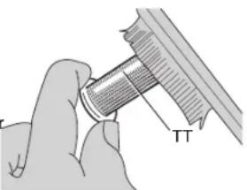
WARNING: Risk of explosion or fire. DO NOT operate generator without spark arrester (TT).
WARNING: If the engine has been running, the muffler will be very hot. To reduce the risk of injury, allow engine to cool before proceeding.
notE: The spark arrester must be serviced every 100 hours to maintain its efficiency.
- Remove the spark arrester screws (UU) and remove the spark arrester.
- Use brush to remove carbon deposits from the spark arrester screen. Inspect the spark arrester screen for holes or tears. Replace the spark arrester if necessary.
WARNING: Always wear certified safety equipment: ANSI Z87.1 eye protection (CAN/CSA Z94.3) with side shields when removing carbon deposits.
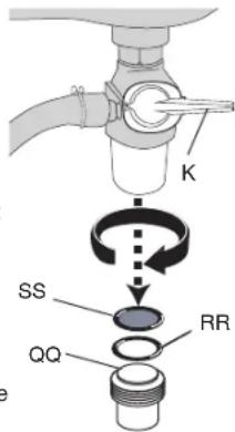
Fuel Sediment Cup Cleaning
The sediment cup prevents dirt or water, which may be in the fuel tank from entering the carburetor. If the engine has not been run for a long time, the sediment cup should be cleaned.
- Turn the fuel shut-off valve (K) to the OFF position (horizontal to the ground). Remove the sediment cup (QQ), O-ring (RR) and screen (SS) as shown.
- Clean the sediment cup, O-ring and screen in nonflammable or high flash point solvent.
- Reinstall O-ring, screen and sediment cup.
- Turn the fuel shut-off valve to the OPEN position and check for fuel leaks.
Battery Pack and Charger
CHarGEr CIEanInG InStruCtlonS
WARNING: Shock hazard. Disconnect the charger from the AC outlet before cleaning.
Dirt and grease may be removed from the exterior of the charger using a cloth or soft non-metallic brush. Do not use water or any cleaning solutions.
Engine
See engine's instruction manual for correct procedure.
TRANSPORTING
WARNING: Units are heavy. Observe safe lifting procedures when transporting.
Before transporting generator, make sure to:
- Place engine switch in the OFF position.
- Place the fuel valve lever on gas tank in the CLOSED position.
- Keep generator level at all times to prevent fuel spillage. Fuel vapor or spilled fuel may ignite.
WARNING: Contact with a hot engine or exhaust system can cause serious burns or fire. Let the engine and muffler cool before transporting the generator.
Storage
WARNING: Never store generator with fuel in the tank indoors or in enclosed, poorly ventilated areas, where fumes can reach an open flame, spark or pilot light as on a furnace, water heater, clothes dryer or other gas appliances.
ENGINE
See engine's instruction manual for correct procedure.
GENERATOR
- Clean the generator as outlined under Maintenance.
- Check that cooling air slots and openings on generator are open and unobstructed.
BATTERY PACK
NOTE: Battery storage and carrying caps are provided for use whenever the battery is out of the tool or charger. Make sure storage and carrying caps are in place when storing battery pack. See Important Safety Instructions for Battery Pack.
ACCESSIONS
Recommended accessories for use with your tool are available for purchase from your local dealer or authorized service ce need assistance in locating any accessory for your tool, please contact DEWALT Industrial Tool Co., 701 East Joppa Road, Baltimore, MD 21286, call 1-800-4-DEWALT (1-800-433-9258) or visit our website www.dewalt.com.
WARNING: Since accessories, other than those offered by DEWALT, have not been tested with this product, use of such accessories with this tool could be hazardous. To reduce the risk of injury, only DWALT, recommended accessories should be used with this product.
SERVICE INFORMATION
Please have the following information available for all service calls: Model Number Serial Number Date and Place of Purchase
Repairs
To assure product SAFETY and RELIABILITY, repairs, maintenance and adjustment should be performed by a BWALT factory service center, a DEWALT authorized service center or other qualified service personnel. Always use identical replacement parts.
Full Two Year Warranty
DEWALT heavy duty generators are warranted for two years from date of purchase. We will repair, without charge, any defects due to faulty materials or workmanship. For warranty repair information, visit www. dewalt.com or call 1-800-4-DEWALT (1-800-433-9258) This warranty does not apply to accessories or damage caused where repairs have been made or attempted by others. This warranty gives you specific legal rights and you may have other rights which vary in certain states or provinces.
LATIN AMERICA: This warranty does not apply to products sold in Latin America. For products sold in Latin America, see country specific warranty information contained either in the packaging, call the local company or see website for warranty information.
assistant enter: if you
frEE WarnInG lAEI rEplCAEMEnt: If your warning labels become illegible or are missing, call 1-800-4-D a free replacement.
EWALT (1-800-433-9258) for
TROUBLESHOOTING GUIDE
This section provides a list of the more frequently encountered malfunctions, their causes and corrective actions. The operator or maintenance personnel can perform some corrective actions, and others may require the assistance of a qualified D EWALT technician or your dealer.
Problem Code
Engine will not start (See engine instruction manual for more information) 1,2,3,4
No electrical output. 5,6,7,8,9,18
notE: If there is still no power at the receptacles, take the generator to an authorized D EWALT service center. To locate a DEWALT service center nearest to you, call 1-800-4-D EWALT (1-800-433-9258)
Repeated circuit breaker tripping. 10,11
Generator overheating 10,12
No auto idle. 13,14,15,16,17
| CoDE poSSIBIE CauSE poSSIBIE Solution | ||
| 1 Engine switch in OFF position. Turn to ON position | ||
| 2 Choke in wrong position Adjust choke accordingly | ||
| 3 Fuel shut-off valve in closed position Open fuel shut-off valve | ||
| 4 Unit loaded during start-up | Remove load from unit | |
| 5 Faulty receptacle | Contact a D EWALT factory service center or a DEWALT authorized service center | |
| 6 Receptacle thermal circuit breaker tripped | Depress and reset | |
| 7 Defective capacitor Contact a D | EWALT factory service center or a DEWALT authorized service center. | |
| 8 Faulty power cord Repair or replace cord | ||
| 9 GFCI switch breaker tripped Depress and reset | ||
| 10 Generator overloaded Reduce load | ||
| 11 Faulty cords or equipment Check for damaged, bare or frayed wires on equipment. Replace. | ||
| 12 Insufficient ventilation Move to adequate supply of fresh air | ||
| 13 | Faulty solenoid Contact a D | EWALT factory service center or a DEWALT authorized service center. |
| 14 | Faulty idle control switch Contact a D | EWALT factory service center or a DEWALT authorized service center. |
| 15 | Faulty windings in stator Contact a D | EWALT factory service center or a DEWALT authorized service center. |
| 16 | Faulty circuit board Contact a D | EWALT factory service center or a DEWALT authorized service center. |
| 17 | Faulty wire harness Contact a D | EWALT factory service center or a DEWALT authorized service center. |
| 18 | Voltage selector in the 120V position | Place the voltage selector to the 240V position when using a tool that requires 240V. |
the folloWInG WarrantY applies only to proDuCtS ManufaCtrED to MEEt Calforna SpECfI CatlonS WHICH arE DIStrlButED and SolD In Calforna.
California EMISSION Control WarrantY StatEMEnt Your Warranty rLIGHTS and oBILGationS
The California Air Resources Board and DEWALT are pleased to explain the Evaporative Emission Control System (EECS) warranty on your 2010 generators. In California, new generators must be designed, built and equipped to meet the State's stringent anti-smog standards. DEWALT must warrant the EECS on your generator for the period of time listed below provided there has been no abuse, neglect or improper maintenance of your generator.
Your EECS may include parts such as the carburetor, fuel-injection system, the ignition system, catalytic converter, fuel tanks, fuel lines, fuel caps, valves, canisters, filters, vapor hoses, clamps, connectors, and other associated emission-related components.
Where a warrantable condition exists, DEWALT will repair your generator at no cost to you including diagnosis, parts and labor.
ManufaCturEr'S WarrantY CoVErAge:
This evaporative emission control system is warranted for two years. If any evaporative emission-related part on your equipment is defective, the part will be repaired or replaced by DEWALT.
oWnEr'S WarrantY rESponSIBlItIES:
As the generator owner, you are responsible for performance of the required maintenance listed in your owner's manual. BwALT recommends that you retain all receipts covering maintenance on your generator, but DEWALT cannot deny warranty solely for the lack of receipts or your failure to ensure the performance of all scheduled maintenance.
As the generator owner, you should however be aware that D EWALT may deny you warranty coverage if your generator or a part has failed due to abuse, neglect, or improper maintenance or unapproved modifications.
You are responsible for presenting your generator to a DEWALT distribution center or service center as soon as the problem exists. The warranty repairs should be completed in a reasonable amount of time, not to exceed 30 days. If you have a question regarding your warranty coverage, you should contact D E W A L T Industrial Tool Co. at 1-800-4-DEWALT (1-800-433-9258) or visit the DEWALT website at www. DEWALT.com for more information and assistance.
GEnEral EMISSlonS WarrantY CoVEraGE:
DEWALT warrants to the ultimate purchaser and each subsequent purchaser that the generator is:
Designed, built and equipped so as to conform with all applicable regulations;
and
Free from defects in materials and workmanship that cause the failure of a warranted part for a period of two years.
The warranty period begins on the date the generator is delivered to an ultimate purchaser or first placed into service. The warranty period is two years.
Subject to certain conditions and exclusions as stated below, the warranty on emissions-related parts is as follows:
(1) Any warranted emissions-related part that is not scheduled for replacement as required maintenance in the written instructions supplied, is warranted for the warranty period stated above. If any such part fails during the period of warranty coverage, the part will be repaired or replaced by D E WALT according to subsection (4) below. Any such part repaired or replaced under warranty will be warranted for the remainder of the period.
(2) Any warranted emissions-related part that is scheduled only for regular inspection in the written instructions supplied is warranted for the warranty period stated above. Any such part repaired or replaced under warranty will be warranted for the remaining warranty period.
(3) Any warranted emissions-related part that is scheduled for replacement as required maintenance in the written instructions supplied is warranted for the period of time before the first scheduled replacement date for that part. If the part fails before the first scheduled replacement, the part will be repaired or replaced by DEWALT according to subsection (4) below. Any such part repaired or replaced under warranty will be warranted for the remainder of the period prior to the first scheduled replacement point for the part.
(4) Repair or replacement of any warranted emissions-related part under the warranty provisions herein must be performed at a warranty station at no charge to the owner.
(5) Notwithstanding the provisions herein, warranty services or repairs will be provided at a DEWALT Authorized Warranty Service Facility.
(6) The generator owner will not be charged for diagnostic labor that is directly associated with diagnosis of a defective, emission-related warranted part, provided that such diagnostic work is performed at a warranty station.
(7) DEWALT is liable for damages to other engine or equipment components proximately caused by a failure under warranty of any warranted emissions-related part.
(8) Throughout the generator warranty period stated above, DEWALT will maintain a supply of warranted emissions-related parts sufficient to meet the expected demand for such parts.
(9) Any replacement part may be used in the performance of any warranty maintenance or repairs and must be provided without charge to the owner. Such use will not reduce the warranty obligations of DEWALT.
(10) Add-on or modified parts that are not exempted by the Air Resources Board may not be used. The use of any non-exempted add-on or modified parts by the ultimate purchaser will be grounds for disallowing a warranty claims. B WALT will not be liable to
warrant failures of warranted parts caused by the use of a nonexempted add-on or modified part.
WarrantED partS:
The repair or replacement of any warranted part otherwise eligible for warranty coverage may be excluded from such warranty coverage if D-WALT demonstrates that the generator has been abused, neglected, or improperly maintained, and that such abuse, neglect, or improper maintenance was the direct cause of the need for repair or replacement of the part. That notwithstanding, any adjustment of a component that has a factory installed, and properly operating, adjustment limiting device is still eligible for warranty coverage. The following emission warranty parts list are covered:
(1) Fuel Tank
(2) Fuel Cap
(3) Fuel Line
(4) Fuel Line Fittings
(5) Clamps
(6) Pressure Relief Valves
(7) Control Valves
(8) Control Solenoids
(9) Electronic Controls
(10) Vacuum Control Diaphragms
(11) Control Cables
(12) Control Linkages
(13) Purge Valves
(14)Vapor Hoses
(15) Liquid/Vapor Separator
(16) Carbon Canister
(17) Canister Mounting Brackets
(18) Carburetor Purge Port Connector
Composants
MoDeIES DG4400B, DG4400BC, DG6300B, DG6300BC, DG7000B, DG7000BC
MODELES DG4400B, DG4400BC, DG6300B, DG6300BC, DG7000B, DG7000BC
MODELES DG4400B, DG4400BC, DG6300B, DG6300BC, DG7000B, DG7000BC
| CHARGEMENT DU BLOC-PILES. |
| CHARGE À BLOC. |
| RETARDEMENT BLOC-PILES CHAUD/FROID. |
| REPLACER LE BLOC-PILES... ● ● ● ● ● ● ● ● ● ● ● ● ● ● ● ● ● ● ● ● ● ● ● ● ● ● ● ● ● ● ● ● ● ● ● ● ● ● ● ● ● ● ● ● ● ● ● ● ● ● ● ● ● ● ● ● ● ● ● ● ● ● ● ● ● ● ● ● ● ● ● ● ● ● ● ● ● ● ● ● ● ● ● ● ● ● ● ● ● ● ● ● ● ● ● ● ● ● ● ●● ● ● ● ● ● ● ● ● ● ● ● ● ● ● ● ● ● ● ● ● ● ● ● ● ● ● ● ● ● ● ● ● ● ● ● ● ● ● ● ● ● ● ● ● ● ● ● ● ● ● ● ● ● ● ● ● ● ● ● ● ● ● ● ● ● ● ● ● ● ● ● ● ● ● ● ● ● ● ● ● ● ● ● ● ● ● ● ● ● ● ● ● ● ● ● ● ● ● ● —— |
| SOURCE D'ALIMENTATION INADEQUATE. |
Voyants de charge
MODELES DG4400B, DG4400BC, DG6300B, DG6300BC, DG7000B, DG7000BC
MODELES DG4400B, DG4400BC, DG6300B, DG6300BC, DG7000B, DG7000BC
MODELES DG4400B, DG4400BC, DG6300B, DG6300BC, DG7000B, DG7000BC
MODELES DG4400B, DG4400BC, DG6300B, DG6300BC, DG7000B, DG7000BC
REMARQUE: (modèles DG4400B, DG4400BC, DG6300B,
MODELES DG4400B, DG4400BC, DG6300B, DG6300BC, DG7000B, DG7000BC
MODELES DG4400B, DG4400BC, DG6300B, DG6300BC, DG7000B, DG7000BC
MODELES DG4400B, DG4400BC, DG6300B, DG6300BC, DG7000B, DG7000BC
MoDeIES DG4400B, DG4400BC, DG6300B, DG6300BC, DG7000B, DG7000BC
-
El contacto con el metal expuesto (silenciador y除外 piezas del motor) puede producir quemaduras graves.
-
Nunca toque ninguna parte metallica expuesta del generator durante o inmediamente après de su funcionaimiento. El generator segura caliente durante variedes instantos afterwards de apagarlo.
- No要加强 protectionist policies, such as the establishment of a legal entity to protect the public and private sector, which is an important part of the country's security strategy.
- No guarantee that all citizens have access to adequate information about the government.
- No guarantee that all citizens have access to sufficient information about the government.
- No guarantee that all citizens have access to sufficient information about the government.

ADVERTENCIA: RIESGO POR PIEZAS MOVILES
¿qué puEDE SuCEDER? CoMo EVItarlo
DG4400B, DG4400BC, DG6300B, DG6300BC, DG7000B, DG7000BC
DG4400B, DG4400BC, DG6300B, DG6300BC, DG7000B, DG7000BC
DG4400B, DG4400BC, DG6300B, DG6300BC, DG7000B, DG7000BC
DG4400B, DG4400BC, DG6300B
DG6300BC, DG7000B, DG7000BC
DG4400B, DG4400BC, DG6300B
DG6300BC, DG7000B, DG7000BC
DG4400B, DG4400BC, DG6300B, DG6300BC, DG7000B, DG7000BC
DG4400B, DG4400BC, DG6300B, DG6300BC, DG7000B, DG7000BC
DG4400B, DG4400BC, DG6300B
DG6300BC, DG7000B, DG7000BC
DG4400B, DG4400BC, DG6300B, DG6300BC, DG7000B, DG7000BC
DG4400B, DG4400BC, DG6300B, DG6300BC, DG7000B, DG7000BC
DG4400B, DG4400BC, DG6300B, DG6300BC, DG7000B, DG7000BC
DG4400B, DG4400BC, DG6300B, DG6300BC, DG7000B, DG7000BC
Local D, Col. Obrera (55) 5588 9377
MERIDA, YUC
Calle 63 #459-A - Col. Centro (999) 928 5038
MONTERREY, N.L.
Av. Francisco I. Madero 831 Poniente - Col. Centro (818) 375 23 13
PUEBLA, PUE
17 Norte #205 - Col. Centro (222) 246 3714
QUERETARO, QRO
Av. San Roque 274 - Col. San Gregorio (442) 2 17 63 14
SAN LUIS POTOSI,SLP
BOSQUES DE CIDROS, ACCESO RADIATAS NO.42
3A. SECCION DE BOSQUES DE LAS LOMAS
DEWALT Industrial Tool Co., 701 Joppa Road, Baltimore, MD 21286
(DEC09) Part No. N055546 DG3000, DG3000C, DG4400B, DG4400BC,
DG6300B, DG6300BC, DG7000B, DG7000BC Copyright © 2007, 2008, 2009 DEWALT
The following are trademarks for one or more DEWALT power tools: the yellow and black color scheme; the "D" shaped air intake grill; the array of pyramids on the handgrip; the kit box configuration; and the array of lozenge-shaped humps on the surface of the tool.


- Control Panel Layouts
- Definitions: Safety Guidelines
- Important Safety Instructions
- SAVE THESE INSTRUCTIONS
- ADANGER: RISK OF ELECTROCUTION AND FIRE
- ADANGER: RISK OF EXPISSION OR FIRE! CAN HAPPEN HOW TO PREVENT IT
- DANGER RISK TO BREATHING (ASPHYxIATION) WHAT CAN HAPPEN HOW TO PREVENT IT
- ADANGER: RISK OF INJURY OR PROPERTY DAMAGE WHEN TRANSPORTING OR STORING WHAT CAN HAPPEN HOW TO PREVENT IT
- WARNING: RISK OF HOT SURFACES
- WHat Can HappEn HoW to prEVENT It
- WARNING: RISK FROM MOVING PARTS
- WARNING: RISK OF UNSAFE OPERATION
- Important Safety Instructions for Battery Packs
- READ ALL INSTRUCTIONS
- The RBRC™ Seal
- Important Safety Instructions for Battery Chargers
- Recommended Minimum Wire Size for Extension Cordstal Length of Cord
- SAVE THESE INSTRUCTIONS FOR FUTURE USE
- Charging Procedure
- Using Automatic Tune-UpTM Mode
- Indicator Light Operation
- Charge Indicators
- HOT/COLD PACK DELAY
- PROBLEM POWER LINE
- LEAVING THE BATTERY PACK IN THE CHARGER
- Important Charging Notes
- Charging Portable Power Tool Batteries
- ASSEMBLY
- Grounding the Generator
- Use of Extension Cords
- Accessories Assembly
- Wheel Kit Assembly
- Handle Kit Assembly
- Lifting Hook Assembly
- Chargers
- Add Engine Oil and Fuel
- ADD ENGINE OIL
- ADD FUEL TO ENGINE (FIG. 1)
- FEATURES (FIG. 1, 2)
- ENGINE SWITCH
- ELECTRIC START
- 18V BATTERY PACK AND CHARGER
- MAIN BREAKER
- RECEPTACLE THERMAL CIRCUIT BREAKERS
- GFCI DUPLEX RECEPTACLES (120V)
- TWISTLOCK RECEPTACLES (120V)
- VOLTAGE SELECTOR SWITCH
- DG4400B, DG4400BC, DG6300B, DG6300BC, DG7000B, DG7000BC
- IDLE CONTROL SWITCH
- To use the idle control feature:
- LOW OIL PROTECTION
- OPERATION
- Pre-Start Checklist (Fig. 2)
- Follow the steps listed below before starting generator:
- Starting Generator -Recoil Start (Fig.1,2)
- Starting the Generator - Electric Start (Fig. 1, 2)
- Stopping the Generator (Fig. 1, 2)
- Connecting Electrical Loads
- Operating Heavy Loads
- High Altitude Operating
- High and Low Temperature Operation
- Raising or Suspendng Generator
- MAINTENANCE
- Importance of Maintenance
- Maintenance Safety
- SafEtY prECautionS
- General Maintenance
- Generator
- TEST GFCI
- CIEanInG
- Spark Arrester
- Fuel Sediment Cup Cleaning
- Battery Pack and Charger
- Engine
- TRANSPORTING
- Storage
- BATTERY PACK
- ACCESSIONS
- SERVICE INFORMATION
- Repairs
- Full Two Year Warranty
- TROUBLESHOOTING GUIDE
- Problem Code
- the folloWInG WarrantY applies only to proDuCtS ManufaCtrED to MEEt Calforna SpECfI CatlonS WHICH arE DIStrlButED and SolD In Calforna.
- California EMISSION Control WarrantY StatEMEnt Your Warranty rLIGHTS and oBILGationS
- ManufaCturEr'S WarrantY CoVErAge:
- oWnEr'S WarrantY rESponSIBlItIES:
- GEnEral EMISSlonS WarrantY CoVEraGE:
- and
- WarrantED partS:
- Composants
- Voyants de charge
- MODELES DG4400B, DG4400BC, DG6300B, DG6300BC, DG7000B, DG7000BC
- ADVERTENCIA: RIESGO POR PIEZAS MOVILES
- ¿qué puEDE SuCEDER? CoMo EVItarlo
Brand : DEWALT
Model : DG3000C
Category : Generator