ELPMB28 - Projector EPSON - Free user manual and instructions
Find the device manual for free ELPMB28 EPSON in PDF.
| Technical Features | Mounting bracket for EPSON ELPMB28 projector |
|---|---|
| Compatibility | Compatible with several EPSON projector models |
| Materials | Robust metal construction |
| Load Capacity | Up to 10 kg |
| Dimensions | Dimensions designed for easy mounting |
| Usage | Makes installation and adjustment of the projector easier |
| Maintenance | Regularly check the fastenings and the condition of the bracket |
| Safety | Secure installation recommended by a professional |
| General Information | Ideal for professional and home environments |
Frequently Asked Questions - ELPMB28 EPSON
Download the instructions for your Projector in PDF format for free! Find your manual ELPMB28 - EPSON and take your electronic device back in hand. On this page are published all the documents necessary for the use of your device. ELPMB28 by EPSON.
USER MANUAL ELPMB28 EPSON
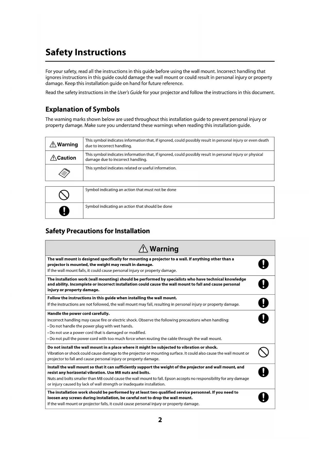
Installation Guide Guide d’installation2 Safety Instructions For your safety, read all the instructions in this guide before using the wall mount. Incorrect handling that ignores instructions in this guide could damage the wall mount or could result in personal injury or property damage. Keep this installation guide on hand for future reference. Read the safety instructions in the User's Guide for your projector and follow the instructions in this document. Explanation of Symbols The warning marks shown below are used throughout this installation guide to prevent personal injury or property damage. Make sure you understand these warnings when reading this installation guide. Safety Precautions for Installation This symbol indicates information that, if ignored, could possibly result in personal injury or even death due to incorrect handling. This symbol indicates information that, if ignored, could possibly result in personal injury or physical damage due to incorrect handling.This symbol indicates related or useful information. Symbol indicating an action that must not be doneSymbol indicating an action that should be doneThe wall mount is designed specifically for mounting a projector to a wall. If anything other than a projector is mounted, the weight may result in damage.If the wall mount falls, it could cause personal injury or property damage. The installation work (wall mounting) should be performed by specialists who have technical knowledge and ability. Incomplete or incorrect installation could cause the wall mount to fall and cause personal injury or property damage.Follow the instructions in this guide when installing the wall mount.If the instructions are not followed, the wall mount may fall, resulting in personal injury or property damage.Handle the power cord carefully. Incorrect handling may cause fire or electric shock. Observe the following precautions when handling:
- Do not handle the power plug with wet hands.• Do not use a power cord that is damaged or modified.
- Do not pull the power cord with too much force when routing the cable through the wall mount. Do not install the wall mount in a place where it might be subjected to vibration or shock. Vibration or shock could cause damage to the projector or mounting surface. It could also cause the wall mount or projector to fall and cause personal injury or property damage. Install the wall mount so that it can sufficiently support the weight of the projector and wall mount, and resist any horizontal vibration. Use M8 nuts and bolts. Nuts and bolts smaller than M8 could cause the wall mount to fall. Epson accepts no responsibility for any damage or injury caused by lack of wall strength or inadequate installation.The installation work should be performed by at least two qualified service personnel. If you need to loosen any screws during installation, be careful not to drop the wall mount.If the wall mount or projector falls, it could cause personal injury or property damage. Warning Caution Warning3 English Location
- Before installing the projector, verify the power supply wiring for the installation location.
- Install the projector away from other electric devices such as fluorescent lights or air conditioners. Some kinds of fluorescent lights could interfere with the remote control of the projector.• Install the projector away from direct sunlight and other bright light sources.
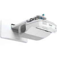
- It is recommended to keep the VGA computer cable length less than 65 ft (20 meters) to reduce external noise. About This Installation Guide This guide describes how to mount the ultra-short-throw projectors BrightLink Pro 1410Wi, BrightLink 475Wi/ 480i/485Wi, and PowerLite 470/475W/480/485W to a wall using the included EPSON wall mount. When you mount the projector on the wall with the wall mount, the wall requires enough strength to hold the projector and the wall mount. This wall mount should be installed on a concrete wall. Confirm the weight of the projector and the wall mount before installation, and maintain the strength of the wall. If the wall is not strong enough, reinforce the wall before installation. Inspect the wall mount on a regular basis to ensure there are no broken parts or loose screws. If there are any broken parts, stop using the wall mount immediately. If the wall mount or projector falls, it could cause personal injury or property damage.Never modify the wall mount.Do not hang on the wall mount or hang a heavy object on the wall mount. If the projector or wall mount falls, it could cause personal injury or property damage. Do not use adhesives, lubricants, or oils to install or adjust the wall mount. If you use adhesives to prevent the screws from loosening or things such as lubricants or oils on the part of the projector attached to the slide plate, the case may crack and cause the projector to fall, resulting in personal injury or property damage. Tighten all screws firmly after adjustment.Otherwise, the projector or wall mount may fall and cause personal injury or property damage.Never loosen the bolts and nuts after installation. Confirm that the screws have not become loose on a regular basis. If you find any loose screws, tighten them firmly. Otherwise, the projector or wall mount may fall and cause personal injury or property damage.When performing wiring, make sure the cable does not come into contact with any screws or bolts. Handling the cable incorrectly may cause fire or electric shock. Do not install the wall mount in a location where the operating temperature for your projector model may be exceeded. Such an environment may damage the projector.Install the wall mount in a place free from excessive dust and humidity to prevent the lens or optical components from becoming dirty.Do not use excessive force when adjusting the wall mount.The wall mount may break, resulting in personal injury. Warning Caution4 1 Package Contents
3 Connecting Devices
1. Installation worksheet for projecting on a pre-installed wall-mounted board
2. Installation worksheet for projecting on a plain wall
3. Installation measurements in inches
4. Installation measurements in millimeters
3. Install the wall plate on the wall
4. Determine the projection distance and pull out the slider
5. Route the cables through the wall mount arm
6. Attach the mount arm to the wall plate
7. Adjust the vertical slide position of the arm
8. Attach the projector to the wall mount
9. Connect the power cord and other cables to the projector
s25 6 Adjusting the Image
1. Turn on the projector
2. Display the mount adjustment test pattern, as described below
7. Use the adjustment knob on the top to adjust the vertical tilt
s36 7 Attaching the Covers
1. Attach the wall plate covers and end cap
2. Attach the cable cover to the projector
s425 English 1 Package Contents
- Use the bolts or screws supplied with the wall mount to install it as directed in this guide. Do not substitute these bolts with any other types.
- You need to use commercially available M8 x 50 mm anchors (at least 3) to attach the wall plate to the wall.
- Gather the tools and parts you need before you begin installation, including a #3 cross-head screwdriver. Shape Name Quantity ApplicationM4 x 12 mm hexagon socket head cap bolt with washer/spring washer6 For wall plate assembly4 For 3-axis adjustment unit/wall mount installation 4 For slide plate/projector installation2 For slide plate/3-axis adjustment unit installation (secured when shipped)M6 x 20 mm hexagon shoulder bolt with washer/spring washer1 For wall mount/wall plate installation (secured when shipped)M6 x 20 mm cross recessed head shoulder screw with plastic washer Hexagon wrench (for M4)Wall plate coverWall mount Template sheet(for installing the wall plate)End cap3-axis adjustment unit (attached to slide plate when shipped)Open-ended wrench13 mm (for M8 and M6) x 6 mm (for hexagonal shaft)Wall plate VGA computer cable (may be included with projector or wall mount)Slide plate6 2 Specifications Wall plate The wall plate is in three piece when shipped, and the middle piece is attached to the wall mount arm. Use the included M4 x 12 mm bolts (x6) to attach the separate pieces together before mounting the projector. See page 26 for instructions. Vertical slide adjustment range Item Specification Additional information Reference Page Wall mount weight (including the 3-axis adjustment unit, slide plate, wall plate, wall plate cover, and end cap) Approx. 16.3 lb (7.4 kg) Wall mount: 6.2 lb (2.8 kg) 3-axis adjustment unit: 2.4 lb (1.1 kg) Slide plate: 1.5 lb (0.7 kg) Wall plate: 5.5 lb (2.5 kg) Wall plate cover and end cap: 0.7 lb (0.3 kg)
Maximum load capacity 15.4 lb (7 kg) — — Forward/backward slide adjustment range 0 to 12.2 in. (310 mm) Arm slide adjustment range: 0 to 9.8 in. (248 mm) Adjustment from 3-axis adjustment unit installation position: 2.4 in. (62 mm) Refer to the illustration below Vertical slide adjustment range ± 1.5 in. (38 mm) — Refer to the illustration below Horizontal roll adjustment range ± 3° Fine adjustments possible with adjustment knob
Horizontal rotation adjustment range ± 3° Fine adjustments possible with adjustment knob
Vertical tilt adjustment range ± 3° Fine adjustments possible with adjustment knob
Horizontal slide adjustment range ± 1.8 in. (45 mm) — Refer to the illustration below 4.7 in. (120 mm)1.2 in. (30 mm)1.3 in. (33 mm)2.9 in. (75 mm)4.2 in. (106.5 mm)3.1 in. (79 mm)1.6 in. (40 mm)4.4 in. (112 mm)8.0 in. (203 mm)6.3 in. (160 mm)8.4 in. (213 mm)18 in. (456 mm)8.7 in. (222 mm)9.7 in. (246 mm)1.5 in. (38 mm)1.5 in. (38 mm)7 English Horizontal slide adjustment range Forward/backward slide adjustment range Arm slide adjustment range Adjustment from 3-axis adjustment unit installation position By changing the installation position of the 3-axis adjustment unit to the front or back, you can adjust the installation position of the projector. When the screen size is less than 70 inches, install it at the position marked with a stamp on the mount arm. When the screen size is 70 inches or more, install it at the position marked with a stamp on the mount arm. To see these stamps, you need to remove the two top screws and slide out the arm extension.
1.8 in. (45 mm)1.8 in. (45 mm)9.8 in. (248 mm)2.4 in. (62 mm)
stamp stamp8 3Connecting Devices Make sure you have the power cord, computer cable, and other parts at the location where the wall mount is to be installed. Make sure you also have all necessary cables for devices, such as a document camera or microphone, that you will connect to the projector. For details, refer to the User’s Guide on the projector CD or at epson.com/ brightlinkdownloads (U.S.) or epson.ca/brightlinkdownloads (Canada). Some of the illustrations in this guide may look different from your projector, but the instructions are the same. External speakers LAN device Microphone USB cable (for Interactive Functions on BrightLink and BrightLink Pro models) Document camera (EPSON DC-06) Power cord Computer cable (for computer video output) Dedicated USB cable (supplied with document camera) Audio cable (not included) LAN cable (not included) When interacting with a computer, you need a USB cable (unless you are connecting wirelessly to the BrightLink Pro 1410Wi). When using the projector's built-in tools, you do not need a USB cable. For Interactive Use (BrightLink 475Wi/480i/485Wi and BrightLink Pro 1410Wi)9 English Connecting the Control Pad (BrightLink Pro 1410Wi Only) The control pad is included with the BrightLink Pro 1410Wi projector. It provides a convenient alternative to the remote control for turning on the projector, changing the source, and selecting whiteboard mode. You can also use the control pad to capture, print, and save your projected images. You must install the control pad on the same surface as the projector, within the range shown in the shaded area below. You can use the included batteries to power the control pad, or the optional remote control cable set (ELPKC28). Remove the top cover and install the batteries. (If you have the optional remote control cable set, you do not need batteries.)
(2.0 m) 60-inch image 100-inch image Remote control light emitting areas10 The following illustration shows the connections available from the projector to the control pad, and from the control pad to a computer, thumbdrive, and printer. For more information on installing and connecting the control pad, see the Control Pad Installation Guide that came with the projector. Optional remote control cable USB cable USB cable (not included) USB cable USB cable11 English 4 Positioning the Projector BrightLink Pro 1410Wi, BrightLink 475Wi/485Wi, and PowerLite 475W/485W can project up to 100 inches diagonally for a WXGA image or 88 inches diagonally for an XGA image. BrightLink 480i and PowerLite 470/ 480 can project up to 93 inches diagonally for an XGA image. You can project onto a pre-installed whiteboard or directly onto a plain wall. The height of the included wall mount determines the maximum image size and how high the image appears on the wall or whiteboard. The distance of the projector from the wall (once it is mounted on the adjustable arm of the wall mount) also affects image size and position. If you are planning to project on a whiteboard, the image may not fill the entire board, depending on the aspect ratio. If you match the image height to the board’s height, gaps may appear on the sides of the board. Use the following worksheets to determine the proper location of the wall plate on the wall. If you are projecting onto a pre-installed whiteboard, use the worksheet below. If you are projecting on a plain wall, use the worksheet on page 12. Installation worksheet for projecting on a pre-installed wall-mounted board
1. Measure the ceiling height (distance from the floor to the ceiling) _____
2. Measure the height of the board’s image area (h). _____ (h)
3. Measure the width of the board’s image area (w). _____ (w)
4. Measure the distance from the floor to the bottom of the board’s image area (f). _____ (f)
5. Measure the distance from the ceiling to the top of the board’s image area (d). _____ (d)
6. Measure the thickness of the board (distance from the projection surface to the wall) (x). _____ (x)
10 in. (254 mm)—height of wall plate plus cover Required distance from top of image area to wall plate (c) Diagonal size of image area (S) Height of image area (h) Distance from ceiling to top of image area (d) Width of image area (w) Distance from floor to bottom of image area (f)12 Installation worksheet for projecting on a plain wall
7. Determine the aspect ratio of the board or of the images that will be projected. For
new computers or laptops, this will most likely be WXGA (16:10). For older equipment, this will most likely be XGA (4:3). You may need to consult your IT director for this information. ___ 4:3 XGA ___ 16:10 WXGA ___ 16:9 Widescreen
8. Using the tables on pages 16 to 23 for your aspect ratio and desired image height (h),
find the required distance between the top of the image area and the wall plate (c). _____ (c)
9. Determine the position for your projector installation by adding the values for (f), (h),
and (c), plus an additional 10 inches for the height of the wall plate plus the cover. If the ceiling height of your room (as noted in step 1) does not meet the minimum ceiling height required for your board, you may need to select a smaller image size or move the board to a lower position on the wall. _____ (f) _____ (h) _____ (c) +10 inches _____ total
10. After confirming your image size, use tape or a pencil to mark the distance (c) from
the top of the image area on the board to the bottom of the wall plate.
11. Align the line (horizontal) on the template sheet with the (c) mark, then align the
center line on the template sheet with the center of the image area. Follow the instructions on page 25 to install the projector.
1. Measure the ceiling height (distance from the floor to the ceiling). _____
2. Determine the desired aspect ratio of the image. For new computers or laptops, this
will most likely be WXGA (16:10). For older equipment, this will most likely be XGA (4:3). You may need to consult your IT director for this information. ___ 4:3 XGA ___ 16:10 WXGA ___ 16:9 Widescreen
3. Using the tables on pages 16 to 23 for your aspect ratio, select the largest image size
available for your ceiling height. Image height (h) Image width (w) _____ (h) _____ (w)
4. Determine the desired distance from the floor to the bottom of the image area (f).
The recommended minimum distance is 30 inches. Images appearing less than 28 inches from the floor may be obstructed for some viewers. _____ (f)
5. Find the top of the projected image area by adding distances (f) and (h). _____
6. Use the tables on pages 16 to 23 to determine the required distance from the top of
the image area to the bottom of the wall plate (c). _____ (c)
Required distance from top of image area to wall plate (c) Height of image area (h) Distance from floor to bottom of image area (f) Height of wall plate plus cover If the total exceeds the ceiling height, you will need to reduce the image size or reduce the distance from the floor to the bottom of the image area. _____ (c) _____ (h) _____ (f) +10 inches _____ total13 English The tables on the following pages provide installation information for all supported image sizes. The minimum ceiling height is based on an image 30 inches from the floor; if the image is lower, the minimum ceiling height is reduced by the corresponding measurement. Use the worksheets, the illustrations, and the information in the tables on the following pages to determine the projection distance and placement of the wall plate. The recommended range for projection distance (a) as shown on the following pages is 2.5 to 12.2 inches (62 to 311 mm).
8. After confirming your image size, use tape or a pencil to mark the distance (c) from
the top of the image area on the board to the bottom of the wall plate.
9. Align the line (horizontal) on the template sheet with the (c) mark, then align the
center line on the template sheet with the center of the image area. Follow the instructions on page 25 to install the projector. 10 in. (254 mm) —height of wall plate plus cover Required distance from top of image area to wall plate (c) Diagonal image size (S) Ceiling height Distance from ceiling to top of image area (d) Width of image area (w) Distance from floor to bottom of image area (f) Height of image area (h)14 Diagonal image size and mounting position The numbers on the slider measure (b) are the same as the projection distance (a) when the diagonal image size (S) is 70 inches or more. Because the installation position of the projector changes when (S) is less than 70 inches, the numbers for (a) and (b) differ. In order to see the stamp and the numbers on the slider scale, you need to slide out the arm extension. When the diagonal image size is 70 inches or more, mount the 3-axis adjustment unit at the position marked with a stamp. When the diagonal image size is less than 70 inches, mount the 3-axis adjustment unit at the position marked with a stamp. Wall plate Projection surface Offset value for the position of the center of the screen and the center of the wall plate Distance from wall to projection surface
(218 mm)15 English Distance from projection surface to wall plate The distance (c) from the projection surface to the wall plate is the number given when the vertical slide is set to the base position, as shown below. Match the notch on the wall mount to the position of the stamp on the wall plate. The measurements may differ depending on the location where you place the projector. When projecting in Tele, the quality of the projected images may decrease. When using BrightLink Pro 1410Wi, BrightLink 475Wi/485Wi, or PowerLite 475W/ 485W to project images at a 4:3 aspect ratio, the images are resized automatically and the quality of the projected images may decrease. Base position Stamp on plate Notch on mount arm16 Installation Measurements in Inches for BrighLink Pro 1410Wi, BrightLink 475Wi/485Wi and PowerLite 475W/485W Diagonal image size (S) 16:10 WXGA 4:3 XGA 16:9 Widescreen Min. ceiling height* Image width (w) Image height (h) Min. projection distance (a) Slider scale mark (b) Distance from top of image to wall plate (c) Min. ceiling height* Image width (w) Image height (h) Min. projection distance (a) Slider scale mark (b) Distance from top of image to wall plate (c) Min. ceiling height* Image width (w) Image height (h) Min. projection distance (a) Slider scale mark (b) Distance from top of image to wall plate (c) 53” ———— ——
- Based on an image 30 inches from the floor; if the image is lower, the minimum ceiling height is reduced by the corresponding measurement. 77” 89.5 65.3 40.8 6.6 6.6 8.6 95.9 61.6 46.2 9.1 9.1 9.7 88.7 67.1 37.8 7.1 7.1 11.0 78”
Diagonal image size (S) 16:10 WXGA 4:3 XGA 16:9 Widescreen Min. ceiling height* Image width (w) Image height (h) Min. projection distance (a) Slider scale mark (b) Distance from top of image to wall plate (c) Min. ceiling height* Image width (w) Image height (h) Min. projection distance (a) Slider scale mark (b) Distance from top of image to wall plate (c) Min. ceiling height* Image width (w) Image height (h) Min. projection distance (a) Slider scale mark (b) Distance from top of image to wall plate (c)18 Installation Measurements in Inches for BrightLink 480i and PowerLite 470/480 Diagonal image size (S) 4:3 XGA 16:10 WXGA 16:9 Widescreen Min. ceiling height* Image width (w) Image height (h) Min. projection distance (a) Slider scale mark (b) Distance from top of image to wall plate (c) Min. ceiling height* Image width (w) Image height (h) Min. projection distance (a) Slider scale mark (b) Distance from top of image to wall plate (c) Min. ceiling height* Image width (w) Image height (h) Min. projection distance (a) Slider scale mark (b) Distance from top of image to wall plate (c) 52” ———— —— ———— ——
- Based on an image 30 inches from the floor; if the image is lower, the minimum ceiling height is reduced by the corresponding measurement. 75” 93 60.0 45.0 7.4 7.4 7.8 92.4 63.6 39.7 8.6 8.6 12.2 91.4 65.4 36.8 9.2 9.2 14.6 76”
- Based on an image 762 mm from the floor; if the image is lower, the minimum ceiling height is reduced by the corresponding measurement. 77” 2272 1659 1037 168 168 219 2436 1565 1173 231 231 247 2253 1705 959 181 181 278 78”
- Remove the slide plate from the 3-axis adjustment unit ( . ❏ When you mount the projector on the wall with the wall mount, the wall requires enough strength to hold the projector and the wall mount. This wall mount should be installed on a concrete wall. Confirm the weight of the projector and the wall mount before installation, and maintain the strength of the wall. If the wall is not strong enough, reinforce the wall before installation.❏ The combined weight of the projector and the wall mount is 32 lb (14.5 kg).❏ Do not hang the rest of the cable over the wall mount. ❏ Install the wall mount so that it can sufficiently support the weight of the projector and wall mount, and resist any horizontal vibration. Use M8 nuts and bolts. Nuts and bolts smaller than M8 could cause the wall mount to fall. ❏ Epson accepts no responsibility for any damage or injury caused by lack of wall strength or inadequate installation. Warning M4 x 12 mm hexagon socket head cap bolts (x2) Slide plate26 B Assemble the parts
1. Assemble the wall plate.
Assemble the three plates into one unit, and secure them with the M4 x 12 mm hexagon socket head cap bolts (x6) supplied.
2. Attach the slide plate to the projector.
Attach the slide plate to the projector using the M4 x 12 mm hexagon socket head cap bolts (x4) supplied.
3. Extend the mount arm to see the stamps that indicate the two positions for mounting the adjustment
unit. M4 x 12 mm hexagon socket head cap bolts Spring washer Washer M4 x 12 mm hexagon socket head cap bolts Spring washer Washer Slide plate27 English
4. Attach the 3-axis adjustment unit to the wall mount.
- Decide which position you want to use for installing the 3-axis adjustment unit. Mount it at the stamp when the image is less than 70 inches (diagonally), or at the stamp when the projected image is 70 inches or more (diagonally).
- Tighten the M4 x 12 mm hexagon socket head cap bolts (x4) supplied to install the 3-axis adjustment unit. : Less than 70 inches : 70 inches or more M4 x 12 mm hexagon socket head cap bolts Spring washer Washer When the diagonal image is less than 70 inches When the diagonal image is 70 inches or more Bolt installation positions28 C Install the wall plate on the wall
1. Determine the template sheet position.
- From the projection distance table, confirm the screen size (S) and the distance between the projection surface and wall plate (c).
- Align the Image Center line (vertical) of the template sheet with the center line (vertical) of the projection surface. Confirm where the beams or studs are within the wall, and shift the position left or right as necessary. The position can be shifted horizontally left or right from the center line of the projection surface up to a maximum of 1.77 in. (45 mm).
- Align the line (horizontal) on the template with the height of (c).
2. Attach the template sheet to the wall.
Center line of projection surfaceImage Center line of template sheet line of template sheet70.5 mm If you need to install a junction box, you can use the cutout areas in the wall plate for the box. The junction box needs to be recessed into the wall if you want to use the wall plate cover. The power cord will not fit behind the wall plate cover if the junction box is not sufficiently recessed. Caution29 English
3. Determine the position of the wall plate’s mounting holes.
Use at least three mounting holes.
- If you are securing the wall plate in four places, drill the holes indicated by A or B in the illustration below.
- If you are securing the wall plate in three places, drill the holes indicated by C in the illustration below. Steps 4 to 8 below provide instructions for attaching the wall plate to a concrete wall.
4. Drill holes of the following diameters and depths.
5. Remove the template sheet.
6. Use a device such as a dust pump to clean out concrete dust from the hole.
7. Position the wall plate on the wall and insert M8 x 50 mm expansion anchors into the holes. Attach the
nut and tap it with a hammer until the core touches the top of the anchor. Drill diameter 0.33 in. (8.5 mm) Pilot hole depth 1.6 in. (40 mm) Anchor hole depth 1.4 in. (35 mm) Four mounting holes Three mounting holes30
8. Tighten the nut with a wrench to secure the wall plate to the wall.
D Determine the projection distance and pull out the slider
1. Using the tables on pages 16 to 23, check the number for the slider measure (b).
2. Loosen the M4 x 12 mm hexagon socket head cap bolts (x2), and then pull out the slider on the wall
mount. Align the slider with the measure (b+x) that is equal to the slider measure (b) plus the thickness of the projection screen (x). E Route the cables through the wall mount arm M4 x 12 mm hexagon socket head cap bolts (x2) Slider measure31 English F Attach the mount arm to the wall plate
1. Insert the hexagonal shaft at the top of the mount arm into the slot on the wall plate ( ).
2. Insert the M8 hexagon bolt at the bottom of the mount arm into the wall plate ( ).
Take care not to trap the cables between the mount arm and wall plate. Caution Hexagonal shaftM8 hexagonal bolt32
3. Secure the mount arm to the wall plate by tightening the supplied M6 x 20 mm cross recessed head
shoulder screws (x3) with the No.3 cross-head screwdriver ( ).
4. Loosely tighten the M6 x 20 mm hexagon shoulder bolt supplied ( ).
M6 x 20 mm cross recessed head shoulder screws (x3) M6 x 20 mm hexagon shoulder bolt Spring washer Washer33 English G Adjust the vertical slide position of the arm
1. Adjust the vertical slide with the M8 hexagon bolt at the bottom of the wall mount, or the hexagonal
shaft at the top of the wall mount ( ). Start by aligning the notch on the arm with the stamp on the wall plate as shown below. Tightening the M8 hexagon bolt lowers the wall mount, and loosening the bolt raises it. Tightening the hexagonal shaft raises the wall mount, and loosening the shaft lowers it.
2. Tighten the M6 x 20 mm hexagon shoulder bolt to secure the wall mount ( ).
Alignment marks Hexagonal shaft M8 hexagon bolt M6 x 20 mm hexagon shoulder bolt34 H Attach the projector to the wall mount
1. Loosen the two screws and remove the cable cover from the projector.
2. Insert the slide plate into the wall mount from the interface side of the projector ( ).
If you have the wireless LAN module for your product, install it in the projector following the instructions in the projector User’s Guide. Cable coverScrews (x2) Projector interface side Alignment marks Slide plate M4 x 12 mm hexagon socket head cap bolts Spring washer Washer Bolt positions Install wireless LAN module When installing or adjusting the wall mount, do not use adhesives to prevent the screws from loosening and do not use lubricants or oils on the projector slide plate. This may cause the case to crack and the projector to fall, resulting in personal injury or property damage. Warning35 English I Connect the power cord and other cables to the projector Connect any necessary cables such as the power cord, computer cable, HDMI cable, and USB cable to the projector. If you are planning to run the cables inside the wall, make sure you follow all local electrical codes. If you are running the cables outside the wall, use a cable management system to keep the cables from obstructing the image. An optional cable management system is available from Epson (part # ELPCK01). If you connect more than one computer cable or USB cable to the projector, it is a good idea to label the cables on both ends. Power cord Computer cable USB cable Power cord Computer cable USB cable BrightLink 475Wi/480i/485Wi and PowerLite 470/475W/480/485W BrightLink Pro 1410Wi36 6 Adjusting the Image To ensure the best image quality, follow the steps below to adjust the projected image. When using the BrightLink 475Wi/480i/485Wi, follow these guidelines for setting up the projector:
- Make sure the image is evenly rectangular, without distortion.
- Make sure the projector is tilted no more than ±3° vertically and horizontally in relation to the projected image.
- If you must use the Keystone function, make sure the amount of vertical and horizontal keystone correction is no more than ±6. A Turn on the projector B Display the mount adjustment test pattern, as described below
1. Press the [Help] button.
2. Press the [ ] button on the remote control, or the [Wide] button on the control panel.
The test pattern is displayed. Do not make adjustments with the Keystone function of the projector. Doing so may result in a reduction in image quality. Using the Remote ControlBrightLink 475Wi/480i/485WiPowerLite 470/475W/480/485WUsing the Remote ControlBrightLink Pro 1410WiUsing the Control PanelUsing the Remote ControlBrightLink 475Wi/480i/485WiPowerLite 470/475W/480/485WUsing the Remote ControlBrightLink Pro 1410WiUsing the Control PanelUsing the Remote Control Using the Control Panel37 English C Change the aspect ratio if necessary Each time you press the [Aspect] button on the remote control, the aspect name is displayed on the screen and the aspect ratio changes. Change the setting according to the signal for the connected equipment. Alternatively, set the aspect ratio from the Signal menu - Aspect. Following is a list of available aspect settings: BrightLink 480i and PowerLite 470/480
- Auto: Automatically sets the aspect ratio according to the input signal and the Resolution setting (available only for HDMI image sources).
- Normal: Displays images using the full projection area and maintains the aspect ratio of the image. Choose this setting or Auto to automatically resize the image and make the best use of the display area.
- 4:3: Displays images using the full projection area at 4:3 aspect ratio.
- 16:9: Converts the aspect ratio of the image to 16:9. 4:3 ratio images are elongated horizontally to fit. BrightLink Pro 1410Wi, BrightLink 475Wi/485Wi, and PowerLite 475W/485W
- Auto: Automatically sets the aspect ratio according to the input signal and the Resolution setting (available only for HDMI image sources).
- Normal: Displays images using the full projection area and maintains the aspect ratio of the image. Choose this setting or Auto to automatically resize the image and make the best use of the display area.
- 16:9: Converts the aspect ratio of the image to 16:9. 4:3 ratio images are elongated horizontally to fit.
- Full: Displays images using the full width of the projection area, but does not retain the aspect ratio. 4:3 ratio images are elongated horizontally.
- Zoom: Displays images using the full width of the projection area and maintains the aspect ratio of the image. The image may be cut off on the top and bottom depending on its aspect ratio.
- Native: Displays images as is (aspect ratio and resolution are maintained). Black bands may appear or images may be cut off, depending on the resolution. Remote ControlNormalAspect Ratio38 D Adjust the focus
1. Slide the air filter cover switch ( ) to open the air filter cover ( ).
2. Use the focus lever to adjust the focus ( ).
3. After you finish making the adjustment, close the air filter cover.
E Use the adjustment knob on the left side to adjust the horizontal roll
1. Loosen the screw in the following illustration ( ).
2. Turn the orange knob ( ) to adjust the horizontal roll ( ).
3. After you finish making all of the adjustments in steps
E to J, tighten the screw you loosened in
Repeat steps E to J as necessary. It is important to start by loosening the screws. Otherwise, you will not be able to turn the knobs as required for adjusting the image. Focus lever Air filter cover Screw39 English F Use the adjustment knob on the right side to adjust the horizontal rotation
1. Loosen the screws (x2) in the following illustration ( ).
2. Turn the dark blue knob ( ) to adjust the horizontal rotation ( ).
3. After you finish making all of the adjustments in steps s
E to J, tighten the screws (x2) you loosened in . G Use the adjustment knob on the top to adjust the vertical tilt
1. Loosen the screw in the following illustration ( ).
3. After you finish making all of the adjustments in steps E to J, tighten the screw you loosened in
2. After you finish making all of the adjustments in steps
E to J, tighten the M4 x 12 mm hexagon socket head cap bolts (x2). I Adjust the forward/backward slide
1. Loosen the M4 x 12 mm hexagon socket head cap bolts (x2), and then adjust the slider for the wall
2. After you finish making all of the adjustments in steps
2. Adjust the vertical slide with the M8 hexagon bolt at the bottom of the wall mount, or the hexagonal
shaft at the top of the wall mount ( ). Tightening the M8 hexagon bolt lowers the wall mount, and loosening the bolt raises it. Tightening the hexagonal shaft raises the wall mount, and loosening the shaft lowers it.
3. Tighten the M6 x 20 mm hexagon shoulder bolt you loosened in the first step ( ).
K Turn off the display of the test pattern Press the [Esc] button on the remote control or control panel to turn off the test pattern. Hexagonal shaftM8 hexagon bolt M6 x 20 mm hexagon shoulder bolt Tighten all screws firmly. Otherwise, the projector or wall mount may fall and cause personal injury or property damage. Warning42 7 Attaching the Covers A Attach the wall plate covers and end cap If you need to use a security cable, make sure you attach it before installing the wall plate covers. See page 44 for instructions.
1. Attach the wall plate covers ( ). Snap the tabs on the cover into the holes on the wall plate. (If you
need to remove the cover, press the tabs.)
2. Place the end cap with the concave portion facing up ( ).
plaque murale (c) Haut.
plaque murale (c) Haut.