
WCG52424AS - Cooker WHIRLPOOL - Free user manual and instructions
Find the device manual for free WCG52424AS WHIRLPOOL in PDF.

| Features | Details |
|---|---|
| Product type | Cooker |
| Dimensions (W x D x H) | 60 x 60 x 90 cm |
| Cooking type | Gas |
| Number of burners | 4 burners |
| Oven type | Electric |
| Oven capacity | 60 liters |
| Oven functions | Convection, grill |
| Energy | Energy class A |
| Safety | Automatic shut-off, child safety |
| Materials | Stainless steel |
| Maintenance | Easy to clean, smooth surface |
| Included accessories | Grill rack, baking tray |
| Warranty | 2 years |
Frequently Asked Questions - WCG52424AS WHIRLPOOL
User questions about WCG52424AS WHIRLPOOL
0 question about this device. Answer the ones you know or ask your own.
Ask a new question about this device
Download the instructions for your Cooker in PDF format for free! Find your manual WCG52424AS - WHIRLPOOL and take your electronic device back in hand. On this page are published all the documents necessary for the use of your device. WCG52424AS by WHIRLPOOL.
USER MANUAL WCG52424AS WHIRLPOOL
Tools and Parts....3
Convert from Natural Gas to LP Gas 3
Convert from LP Gas to Natural Gas 6
Lighting the Electronic Igniters....7
Flame Height Adjustment - Natural Gas Only.... 8
Complete Burner Adjustment....8
SÉCURITÉ DE LA CONVERSION POUR L'ALIMENTATION AU PROPANE....9
CONVERSIONS POUR L'ALIMENTATION AU PROPANE.... 10
Your safety and the safety of others are very important.
We have provided many important safety messages in this manual and on your appliance. Always read and obey all safety messages.

This is the safety alert symbol.
This symbol alerts you to potential hazards that can kill or hurt you and others.
All safety messages will follow the safety alert symbol and either the word "DANGER" or "WARNING."
These words mean:
DANGER
You can be killed or seriously injured if you don't immediately follow instructions.
WARNING
You can be killed or seriously injured if you don't follow instructions.
All safety messages will tell you what the potential hazard is, tell you how to reduce the chance of injury, and tell you what can happen if the instructions are not followed.
IMPORTANT:
Save for local electrical inspector's use.
Installer: Leave installation instructions with the homeowner.
Homeowner: Keep installation instructions for future reference.
IMPORTANT :
WARNING: If the information in this manual is not followed exactly, a fire or explosion may result causing property damage, personal injury or death.
- Do not store or use gasoline or other flammable vapors and liquids in the vicinity of this or any other appliance.
-
WHAT TO DO IF YOU SMELL GAS:
-
Do not try to light any appliance.
- Do not touch any electrical switch.
- Do not use any phone in your building.
- Immediately call your gas supplier from a neighbor's phone. Follow the gas supplier's instructions.
- If you cannot reach your gas supplier, call the fire department.
- Installation and service must be performed by a qualified installer, service agency or the gas supplier.
WARNING: Gas leaks cannot always be detected by smell.
Gas suppliers recommend that you use a gas detector approved by UL or CSA.
For more information, contact your gas supplier.
If a gas leak is detected, follow the "What to do if you smell gas" instructions.
In the State of Massachusetts, the following installation instructions apply:
■ Installations and repairs must be performed by a qualified or licensed contractor, plumber, or gasfitter qualified or licensed by the State of Massachusetts.
■ If using a ball valve, it shall be a T-handle type.
■ A flexible gas connector, when used, must not exceed 3 feet.
GAS CONVERSIONS
Tools and Parts
Gather the required tools and parts necessary for correct LP gas conversion.
Tools needed
■ Flat-blade screwdriver
■ 7 mm nut driver
Parts supplied
■ LP orifice package (400010467292)
■ Conversion instructions (501931902099)
■ Conversion label (461960247361)
IMPORTANT: Gas conversions from Natural gas to LP gas must be done by a qualified installer. Before proceeding with conversion, shut off the gas supply to the cooktop prior to disconnecting the electrical power.
WARNING
This conversion kit shall be installed by a qualified service agency in accordance with the manufacturer's instructions and all applicable codes and requirements of the authority having jurisdiction. If the information in these instructions is not followed exactly, a fire, explosion or production of carbon monoxide may result causing property damage, personal injury or loss of life. The qualified service agency is responsible for the proper installation of this kit. The installation is not proper and complete until the operation of the converted appliance is checked as specified in the manufacturer's instructions supplied with this kit.
WARNING
Explosion Hazard
Use a new CSA International approved gas supply line.
Install a shut-off valve.
Securely tighten all gas connections.
If connected to LP, have a qualified person make sure gas pressure does not exceed 14" (36 cm) water column.
Examples of a qualified person include:
licensed heating personnel, authorized gas company personnel, and authorized service personnel.
Failure to do so can result in death, explosion, or fire.
Convert from Natural Gas to LP Gas
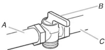
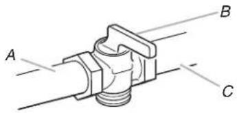
- Turn manual shutoff valve to the closed position.
text_image
A B CA. To cooktop
B. Shutoff valve (closed position)
C. Gas supply line
- Unplug cooktop or disconnect power.
To Convert Gas Pressure Regulator
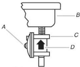
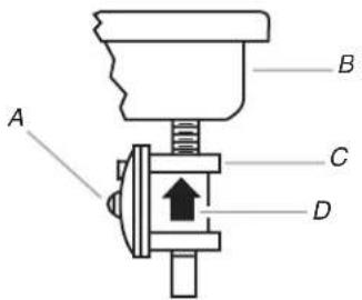
- Remove the access cap by using a wrench, turning the access cap counterclockwise.
text_image
A B C DA. Access cap
B. Rear of cooktop
C. Gas pressure regulator
D. Gas flow
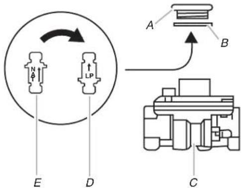
- Remove spring retainer from the cap by turning it counterclockwise. Look at the spring retainer to locate the "NAT" or "LP" position. Turn over the spring retainer so the "LP" is showing on the bottom. Screw the spring retainer back into the cap, turning it clockwise. Reinstall the cap onto the regulator.
text_image
A B C D E N A LPA. Access cap
B. Gasket
C. Gas pressure regulator
- Test the gas pressure regulator and gas supply line.
The regulator must be checked at a minimum 1" (2.5 cm) water column above the set pressure. The inlet pressure to the regulator should be as follows for operation and checking the regulator setting:
LP Gas:
Minimum pressure 10" (25.4 cm) W.C.P. Supply pressure 14" (35.5 cm) W.C.P.
Gas Supply Pressure Testing
Line pressure testing above 12 psi gauge (14" WCP)
The cooktop and its individual shutoff valve must be disconnected from the gas supply piping system during any pressure testing of that system at test pressures in excess of 12 psi (3.5 kPa).
Line pressure testing at 12 psi gauge (14" WCP) or lower
The cooktop must be isolated from the gas supply piping system by closing its individual manual shutoff valve during any pressure testing of the gas supply piping system at test pressures equal to or less than 12 psi (3.5 kPa).
To Convert Surface Burners
- If installed, remove the burner grates.
Use the following charts to match the correct gas orifice spud with the burner location and model being converted.
LP Gas Orifice Spud Chart
| Burner Rating Stamped Number | Size |
| 3,600 BTU 58 0.58 mm | |
| 5,600 BTU 72 0.72 mm | |
| 11,000 BTU 100 1.00 mm | 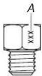 |
| 11,500 BTU 102 1.02 mm |
A. Stamped number
4 Burner Models
| Model No. | Right front | Right rear | Left front | Left rear |
| KGCK346BSS | 58 | 72 | 102 | 72 |
| WCG52424AS | 58 | 72 | 100 | 72 |
| MGC7424AS | 58 | 72 | 100 | 72 |
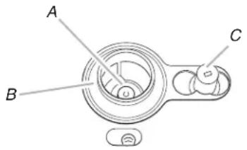
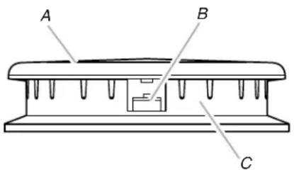
- Remove burner cap.
- Remove the burner base.
NOTE: Remove one burner base at a time. Then replace after converting. Do not disassemble entire cooktop.
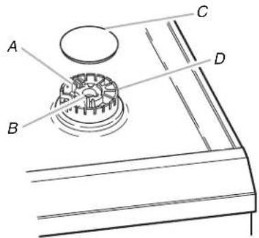
text_image
A B C DA. Igniter electrode
B. Gas tube opening
C. Burner cap
D. Burner base
- Apply masking tape to the end of a 7 mm nut driver to help hold the gas orifice spud in the nut driver while changing it. Press nut driver down onto the gas orifice spud and remove by turning it counterclockwise and lifting out. Set gas orifice spud aside.
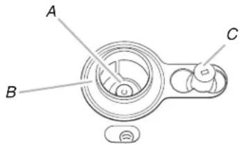
text_image
A B CA. Orifice spud
B. Orifice spud holder
C. Spark electrode
- Replace with correct LP gas orifice spud. See charts in Step 1.
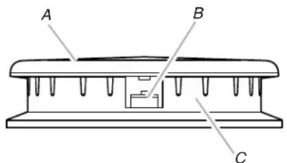
text_image
A B CA. Burner cap
B. Electrode
C. Burner base
- Place Natural gas orifice spuds in plastic parts bag for future use and keep with package containing literature.
- Replace burner base.
IMPORTANT: The igniter electrode is ceramic and could break during conversion. Be sure that the electrode comes through the hole in the burner head.
-
Replace burner cap.
-
Repeat steps 1-8 for the remaining burners.
- Open shutoff valve in the gas supply line. The valve is open when the handle is parallel to the gas pipe.
REMEMBER: Once you have completed converting all the cooktop burners, test the cooktop for leaks by brushing on an approved noncorrosive leak-detection solution. Bubbles will show, indicating a leak. Correct any leaks found.
WARNING

Electrical Shock Hazard
Plug into a grounded 3 prong outlet.
Do not remove ground prong.
Do not use an adapter.
Do not use an extension cord.
Failure to follow these instructions can result in death, fire, or electrical shock.
- Plug in cooktop or reconnect power.
Convert from LP Gas to Natural Gas
- Turn manual shutoff valve to the closed position.
text_image
A B CA. To cooktop
B. Shutoff valve (closed position)
C. Gas supply line
- Unplug cooktop or disconnect power.
To Convert Gas Pressure Regulator
- Remove the access cap by using a wrench, turning the access cap counterclockwise.
text_image
A B C DA. Access cap
B. Rear of cooktop
C. Gas pressure regulator
D. Gas flow
- Remove spring retainer from the cap by turning it counterclockwise. Look at the spring retainer to locate the "LP" or "NAT" position. Turn over the spring retainer so the "NAT" is showing on the bottom. Screw the spring retainer back into the cap, turning it clockwise. Reinstall the cap onto the regulator.

text_image
A B C D E LP NTA. Access cap
B. Gasket
C. Gas pressure regulator
D. NAT position
E. LP position
To Convert Surface Burners
- If they are installed, remove the burner grates.
Use the following charts to match the correct gas orifice spud with the burner location and model being converted.
Natural Gas Orifice Spud Chart
| Burner Rating | Stamped Number | Size |
| 3,600 BTU 90 0.90 mm | ||
| 5,600 BTU 115 1.15 mm | ||
| 11,000 BTU 160 1.60 mm | 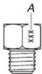 | |
| 11,500 BTU 162 1.62 mm |
A. Stamped number
4 Burner Models
| Model No. | Right front Right rear | Left front Left rear |
| KGCK346BSS | 90 115 162 115 | |
| WCG52424AS | 90 115 160 115 | |
| MGC7424AS | 90 115 160 115 |
- Remove burner cap.
- Remove the burner base.
NOTE: Remove one burner base at a time. Then replace after converting. Do not disassemble entire cooktop.

text_image
A B C DA. Igniter electrode
B. Gas tube opening
C. Burner cap
D. Burner base
- Apply masking tape to the end of a 7 mm nut driver to help hold the gas orifice spud in the nut driver while changing it. Press nut driver down onto the gas orifice spud and remove by turning it counterclockwise and lifting out. Set gas orifice spud aside. See Step 4 of the "Convert from Natural Gas to LP Gas" section.
text_image
A B CA. Orifice spud
B. Orifice spud holder
C. Spark electrode
- Replace with correct Natural gas orifice spud. See the charts in Step 1.
text_image
A B CA. Burner cap
B. Electrode
C. Burner base
- Place LP gas orifice spuds in plastic parts bag for future use and keep with the package containing literature.
- Replace burner base.
IMPORTANT: The igniter electrode is ceramic and could break during conversion. Be sure that the electrode comes through the hole in the burner head smoothly while tightening screws.
- Replace burner cap.
- Repeat steps 1-8 for the remaining burners.
- Open shutoff valve in the gas supply line. The valve is open when the handle is parallel to the gas pipe.
REMEMBER: Once you have completed converting all the cooktop burners, test the cooktop for leaks by brushing on an approved noncorrosive leak-detection solution. Bubbles will show, indicating a leak. Correct any leaks found.
WARNING

Electrical Shock Hazard
Plug into a grounded 3 prong outlet.
Do not remove ground prong.
Do not use an adapter.
Do not use an extension cord.
Failure to follow these instructions can result in death, fire, or electrical shock.
- Plug in cooktop or reconnect power.
Lighting the Electronic Igniters
The cooktop burners use electronic igniters in place of standing pilots. When the cooktop control knob is pushed in and turned to the LITE position, the system creates a spark to light the burner. This sparking continues until the control knob is pushed in.
To Check Operation of the Cooktop Burners:
- Push in and turn knobs to the LITE position. The cooktop burner flame should light within 4 seconds. The first time a burner is lit, it may take longer than 10 seconds to light because of air in the gas line.
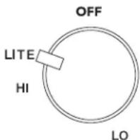
text_image
OFF LITE HI LO- If burners do not light properly, turn the control knob to the OFF position. Make sure the burner cap is in the proper position.
- Check that the power supply cord is plugged in. Check that the circuit breaker has not tripped or the household fuse has not blown.
- Check that the manual shutoff valve is in the open position.
- Check burner operation again.
If one or all of the burners do not light at this point, see "Assistance or Service" section in the Use and Care Guide.
Low Flame Height Adjustment - Natural Gas Only
IMPORTANT: The following instructions are for use with Natural gas only. When LP gas is used, the gas adjustment screw must be tightened as far as it will go.
Each burner flame has been factory set to the lowest position available to provide reliable and constant reignition of the burner; however, each burner can be adjusted.
To Adjust:
-
After lighting, push in and turn each control knob to the LO position.
-
If the burner does not stay lit on the LO position, turn the control knob to the LITE position until the burner lights.
-
Quickly turn the control knob down to the LO position.
If the burner goes out after adjusting, readjust the valve.
To Readjust Valve:
-
Remove control knob(s).
-
Insert a flat-blade screwdriver into the cooktop surface hollow and engage the slotted screw.
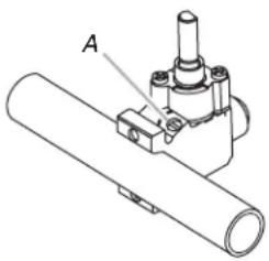
natural_image
Technical line drawing of a mechanical assembly with labeled component A (no text or symbols beyond label)A. Slotted screw
- The flame size can be increased or decreased by turning the screw. Adjust flame until you can quickly turn the control knob from the HI to LO position without extinguishing the flame. The flame should be as small as possible without going out.
NOTE: For higher altitudes, no further burner adjustments are necessary.
Complete Burner Adjustment
- Check burner flame(s) for proper size and shape. The cooktop "low" burner flame should be a steady blue flame approximately 14 " (0.64 cm) high.

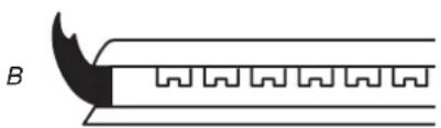
natural_image
Pure diagram of a mechanical component with a curved blade and zigzag grooves, no text or symbols present.A. Low flame
B. High flame
-
Completely fill out the conversion label (4619 602 47361) and attach label to bottom of the cooktop next to the rating tag. Do not cover the rating tag with the conversion label.
-
Save the orifices removed from the cooktop along with these instructions for future reference.
-
Read "Sealed Surface Burners" section in the Use and Care Guide supplied with the cooktop.
SÉCURITÉ DE LA CONVERSION POUR L'ALIMENTATION AU PROPANE
text_image
A B C D E N A LPtext_image
A B C D E LPtext_image
OFF LITE HI LOnatural_image
Technical line drawing of a mechanical assembly with labeled component A (no text or symbols beyond label)A. Vis à fentes