PG220 - Lawn mower Gianni Ferrari - Free user manual and instructions
Find the device manual for free PG220 Gianni Ferrari in PDF.

User questions about PG220 Gianni Ferrari
0 question about this device. Answer the ones you know or ask your own.
Ask a new question about this device
Download the instructions for your Lawn mower in PDF format for free! Find your manual PG220 - Gianni Ferrari and take your electronic device back in hand. On this page are published all the documents necessary for the use of your device. PG220 by Gianni Ferrari.
USER MANUAL PG220 Gianni Ferrari

MANUALE D'ISTRUZIONE
USER'S MANUAL
NOTICE TECNIQUE
natural_image
Line drawing of a small utility vehicle with two additional motors, no text or symbols presentIL PRESENTE MANUALE E SPROVISTO DEL CERTIFICATO DI DONFORMITA E PERTANDO UTILIZZABILE ESCLUSIVAMENTE AD USO INTERNO ALLA RETETI VENDITA GIANNI FERRARI E NON DIVULGABILE ALL'UTENTE FINALE
THE CERTIFICATE OF CONFORMITY MISSES IN THIS MANUAL: THE MANUAL IS ONLY FOR GIANNI FERRARI SALES NETWORK AND IT DOESN'T MAY BE SPREAD TO THE FINAL USERS.
LE PRÉSENT MANUEL EST DEPOURVU DU CERTIFICAT DE CONFORMITÉ ET EST DESTINÉ SEULEMENT A LES DISTRIBUTEURS GIANNI FERRARI ET N'EST PAS DIVULGABILE À L'UTILISATEUR FINAL
DIESES HANDBUCH ENTHÄLT KEINE KONFORMITÄTSERKLÄRUNG UND KANN AUSSCHL Eßlich von GIANNI FERRARI-HANDLER BENUTZT WERDEN, DART ABSOLUT NICHT AM ENDKUNDE AUSGETEILT WERDEN
pag.
6....MANUALE D'ISTRUZIONE LINGUA ORIGINALE
IT
20 ...... USER'S MANUAL
EN
33......NOTICE TECNIQUE
FR
47 ...... TECHNISCHES HANDBUCH DE
61 MANUAL TÉCNICO ES
75 INSTRUKTIONBOG
DK
88 ...... TECHNISCH HANDBOEK NL
ILLUSTRATIONS AND DIAGRAMS
NOTES FOR THE DISPOSAL OF THE PRODUCT VALID FOR THE EUROPEAN COMMUNITY 20
-
NAMEPLATE CE 21
-
TO OUR COSTUMERS....21
-
USER'S RESPONSIBILITY 21
-
SAFETY STANDARDS 21
3.1 SLOPES 22
3.2 TRANSPORT AND UNLOADING 22
- TECHNICAL FEATURES 23
4.1 ENGINE WEIGHTS 23
4.2 LAWNMOWER DEVICE/EQUIPMENT 24
4.3 LEVEL OF ACOUSTIC POWER....24
4.4 OPERATOR 24
-
CONTROLS AND INSTRUMENTS....24
-
USING CONTROLS AND INSTRUMENTS 25
6.1 FORWARD - REVERSE 25
6.3 DIFFERENTIAL LOCKING DEVICE 25
6.4 BY-PASS LEVER 25
6.5 HAND THROLLE 25
6.6 ENGINE STARTING....25
6.7 P.T.O 25
6.8 HYDRAULIC LIFT OF THE EQUIPMENT 25
6.9 HYDRAULIC TILTING OF TRAY 25
6.10 ELEVATOR 25
6.11 DESCRIPTION FUNCTIONS COMPUTER....25
- WIRING DIAGRAM....26
7.0 COLOUR PALETTE 26
7.1 DAIHATSU 950 D 26
7.2 DAIHATSU 950 G 26
7.3 KUBOTA D 902 27
7.4 STRADALE KUBOTA D 902 DAIHATSU 950D/950G 27
7.5 BRIGGS & STRATTON....28
7.6 SWITCH DIAGNOSTICS 28
-
STARTING THE ENGINE....28
-
DRIVING THE MACHINE 28
-
CUTTING AND AUTOMATIC GRASS COLLECTION....29
-
STOPPING THE MOTOR....29
-
TANK FILLING....29
-
ORDINARY MAINTENANCE 29
13.1 ADD MOTOR OIL 29
13.2 ADD COOLING FLUID 29
13.3 ADD HYDRAULIC SYSTEM OIL 29
13.4 ADD FRON AXIAL OIL 29
13.5 BATTERY 29
13.6 AIR FILTER 29
13.7 RADIATOR NET 30
13.8 MOTOR NET 30
13.9 MOTOR OIL FILTER 30
13.10 TYRE PRESSURE 30
13.11 BELT TENSION ADJUSTEMENT 30
13.12 CLEANING THE MACHINE.... 30
13.13 BASKET OVERTURN, CYLINDER GREASE NIPPLE 30
13.14 BASKET OVERTURN, CYLINDER GREASE NIPPLE 30
13.15 PDP GREASE NIPPLE 30
13.16 PEDAL GREASING 30
13.17 HYDRAULIC INSTALLATION FILTER 30
-
EXTRAORDINARY MAINTENANCE 30
-
INACTIVITY OF MOWER DECK....30
-
ROAD TRANSPORT....31
-
SAFETY STICKERS 31
-
NOTES....31
-
TABLE MAINTENANCES 32
-
ERROR CODE DISPLAY 33
NOTES FOR THE DISPOSAL OF THE PRODUCT VALID FOR THE EUROPEAN COMMUNITY

Do not dispose the product as a solid urban waste but dispose it by dropping it at a dumping site. By salvage dumping the product you risk to pollute the nature. If the product is provided with a battery, you must dump the battery in a separate container as the battery contains highly toxic substances. The above shown figure represent a local garbage bin. It is absolutely forbidden to throw the product in such a bin. The introduction after the 1st of July 2006 of products not complying with the decree law 151 (directive RoHS RAEE) is punished by Law.
0. NAMEPLATE CE
See figure 0.
1) Constructor's address
2) Model
3) Meight
4) Engine
5) Construction's year
1. TO OUR COSTUMERS

We are pleased to welcome you as one of our customers. To ensure best possible performance of your machine as well as for useful tips for using and maintaining it, we kindly ask you to read through carefully the User's Manual. The engines PG - SR can be fitted with various equipments: it is the refore important that the user studies, in addition to this manual, also the manual referring to the equipment that he intends to mount on his engine. The machine has been planned and designed to give best performance under difficult conditions. Its working performance largely depends on course on its maintenance. Should queries arise that have not been dealt with with in these instructions, then please contact your dealer who will be able to assist you further.

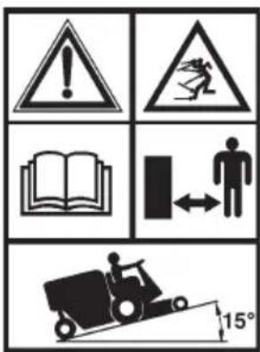
THIS SIGN IMPLIES THAT SAFETY REGULATIONS MUST BE COMPLIED WITH AT ALL TIMES BY THE USER SO AS TO AVOID ACCIDENTS. PLEASE, BE CAREFUL WHEN YOU SEE THIS SIGN. IT IS FOR YOUR AND OTHER PEOPLE'S SAFETY.
2. USER'S RESPONSIBILITY
It is imperative that the user reads through this manual carefully so as to become acquainted with its working procedure, maintenance of parts and proper lubrication according to our instructions. The user is also responsible for checking, repairing and for possible replacement of wornout parts which could cause injuries. The user is responsible for damages caused to third parties by improper use. The machine must be used and maintained only by persons with a good knowledge of its specific features and who have fully understood the safety rules. Never let children or minors near the machine.
Local laws, if any, may state a minimum age for the operator. Never take passengers.
Only use attachments and accessories which have been recommended and supplied by your dealer.
It is strictly prohibited to do any alterations or reconstructions to the machine which are not mentioned in this manual.
WHEN USING THE MACHINE, THE OPERATOR MUST SCRUPULOUSLY OBSERVE THE SAFETY RULES CONTAINED IN THIS MANUAL, THE RULES FOR THE PREVENTION OF ACCIDENTS, OTHER GENERAL SAFETY RULES, THE PROVISIONS OF WORK MEDICINE.
3. SAFETY STANDARDS
ONLY A CAREFUL USER IS A GOOD USER
If you follow the Safety Instructions in the manual you can avoid accidents.
MAIN PART
1) Read through carefully each section of these instructions.
2) Check the machine before every use for defect, for e.g. loose screws and bolts, loosened or damaged blades or other parts which are not secure. It is absolutely forbidden to use the machine in improper conditions.
Therefore, before starting your machine go through the control and service instructions as recommended.
3) Before starting the machine acquaint yourself with all the parts and with the checking system.
4) The machine should only be used by adults with experience. Don't let children use it.
Avoid using the lawnmower if you do not feel physically fit for the job.
5) Keep people within a certain security distance as explained hereafter.
6) Only use original parts and accessories. Do not make any changes thereto.
For information, please consult your dealer.
7) Replace lost or damaged safety stickers or warning labels. Chek the list of safety stickers in the "SAFETY PRE CAUTIONS" section of this manual. Wipe dust and dirt off the stickers.
8) Keep hands and feet, as well as your body away from the moving parts.
9) Never use the machine without protection and covers in the right position and perfect condition.
Do not use the machine if its safety devices are not perfectly efficient.
For no reason, tamper with the machine safety devices.
10) Should an object have been run over or got stuck, stop immediately. Turn off the engine and remove the ignition key. Disengage the P.T.O., put the attachment onto the ground and inspect it. Do not start using the machine until you are sure that it is in perfect working order.
11) When you have finished working with the machine, disengage the P.T.O., put the attachment lower down so that it touches the ground, turn off the engine and remove the key.
12) Never start the engine in a closed room. Exhaust fumes are poisonous.
Before carrying out maintenance operations on the machine make sure that the same is off.
Before intervening on the electrical installation, disconnect the power cables from the battery terminals.
13) Be careful that flames or sparks do not get near the petrol tank.
14) Never park on slopes.
15) Machine speed should be suited to the ground you are working on.
16) Working on slopes requires extreme caution and reduced speed.
17) When using the machine wear suitable clothing, glasses, gloves and any other protective clothing.
18) Only use the machine with good visibility.
19) Do not use the machine for towing.
20) It is absolutely forbidden to start the machine if the equipment is not correctly mounted.
21) All drivers should receive a professional and practical training. Such training should highlight the following:
- the necessity of paying attention and being concentrated when working on machines where the driver is sitting.
- a machine sliding down a slope can be brought again under control by pulling the brakes. The main causes for the loss of control are:
a) insufficient grip of the wheels;
b) driving too fast;
c) inadequate braking;
d) type of machine unsuitable for the job required;
e) lack of awareness of the effect of the condition of the ground, particularly of slopes ;
f) the equipments are wrongly attached and the loads are consequently badly distributed.
22) During the phases of work, always wear strong shoes and long trousers. Do not use the machine when you are bare-footed or wearing sandals.
23) Inspect thoroughly the area where the machine is to be used and remove all the object that could be thrown by the machine.
24) Always disengage the P.T.O. when transferring the machine.
3.1 SLOPES
See figure 3.1
- Do not use the machine on longitudinal slopes of more than 15^ .
- Do not use the machine on lateral slopes higher of more than 12°.
- Do not proceed on slopes of any kind (lateral or longitudinal) with the plate lifted.
- Do not stop or start suddenly the machine when going up or down a slope.
- Proceed with low speed on slopes or narrow curves.
- Pay attention to any road humps, potholes or other hidden dangers. If the ground is irregular, the machine can overturn more easily.
- Do not operate in the proximity of shoulders, ditches or river banks; the machine could suddenly overturn if a wheel goes beyond the edge of the latter, or if the shoulder cedes.
3.2 TRANSPORT AND UNLOADING
See figure 3.2
The machine is heavy and can cause serious crushing damages.
Load and unload it with care and use loading ramps.
Transport the machine on a homologated trailer. During transport, use the parking brake and fix the machine with homologated devices, such as belts, chains or ropes.
N.B.: If the machine is packed and mounted on its pallet, it is possible to move it with a forklift.
CAPACITY 1200 Kg

IMPORTANT:
The parking brake is not sufficient for locking the machine during transport. Fix appropriately the machine to the vehicle with homologated devices.
4. TECHNICAL FEATURES
See figure 4.
Measurement in mm.
The measurements shown also apply for "SR" models.

See technical manual for the equipment
| Engine | PG/SR 270D PG/950 D | SR 210D PG/SR 902 | 250 PG/SR 220 | B&S22 HP |
| DAIHATSU | KUBOTA | |||
| Engine power | 26,5 21 31 22 | |||
| Displacement (cc.) | 952 898 952 627 | |||
| N° of cylinders | 3 3 3 2 | |||
| RPM | 3600 3200 3600 | |||
| Driving wheels | Front with possibility of differential locking | |||
| Type of progress | Hydrostatic | |||
| Service brake | Hydrostatic | |||
| Parking brake | Mechanical disk | |||
| Max speed (Km/h) | 11 | |||
| Fuel tank (L) | 17 | |||
| Basket capacity (L)* | 600 | |||
| Max container capacity(Kg) | 80 | |||


Only "PG" models

Only "SR" models
4.1 ENGINE WEIGHTS
| Model Mass (Kg) | |
| PG 210 D 3R | 760 |
| PG 210 D 4R | 770 |
| PG 210 D 4R Elevator | 820 |
| SR 210 D 4R | 760 |
| PG 220 | 584 |
| PG 220 Elevator | 648 |
| PG 220 3R | 557 |
| PG 270 D | 695 |
| PG 270 D Elevator | 740 |
| SR 270 D | 725 |
| PG 250 | 695 |
| PG 250 Elevator | 740 |
| SR 250 | 725 |
4.2 LAWNMOWER DEVICE/EQUIPMENT
Consult the specific technical manual for the equipment or mower
| PG S | R Attachments | Model | |
| X | Collection deck | Piatto 112 | |
| Piatto 126 SA | |||
| Piatto 130 RCA | |||
| X | X | Side discharge deck | Piatto 130 SL |
| X | X | Rear discharge with mulching kit | Piatto 130 SP |
| X | X | Mulching deck with side discharge | Piatto 150 SM |
| X | X | Flail mower | GF 135 |
| GF 110 | |||
| X | X | Aerator | Arieggiatore |
| X | Collecting sweeper | Hydraulic Sweeper | |
| X | Vacuum hose | Tubo aspirafoglie | |
| X | X | Grader blade | Lama frontale apripista |
| X | X | Double-stage snow thrower | TN130 |
| X | X | Rotary broom | Spazzatrice PG 140 |
| X | Sweeper for Synthetic grass | Spazzatrice PG 110 C/F | |
| Spazzatrice PG 110 S/F | |||
| X | X | Spreader Polaro | Spargisale |
| Width of cut L = 110 cm L = 130 cm | ||
| Found | 98,5 dB (A) 104,5 dB (A) | |
| Guaranteed | 100 dB (A) 105 dB (A) | |
4.4 OPERATOR
• Exposition of acceleration of superior limbs: ....../< 2,5 m/s ^2 .
• Exposition of body acceleration: 0,5 m/s ^4 .
- Noise value at operator's place: 89,5 dB(A)
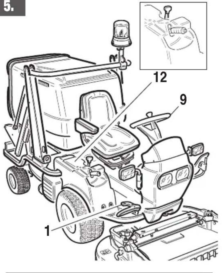
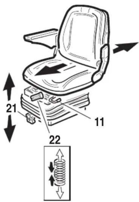
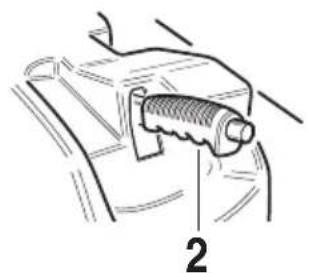
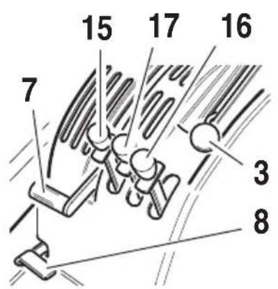
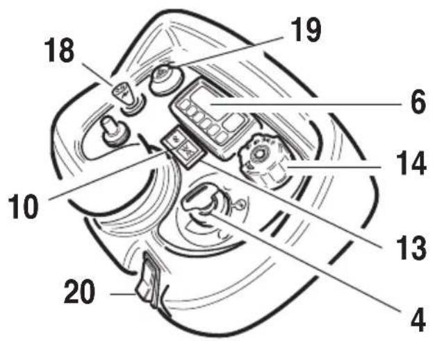
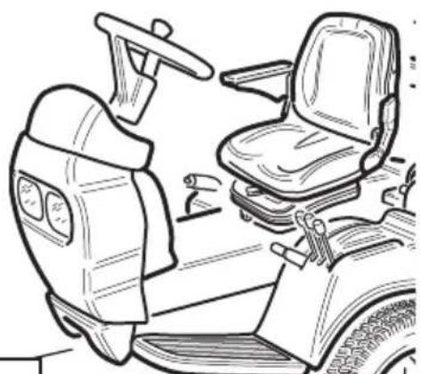
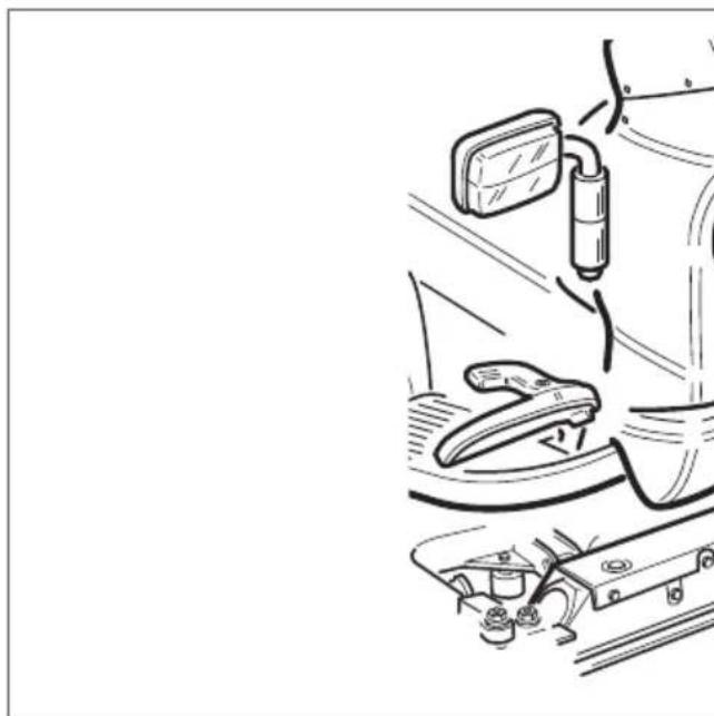
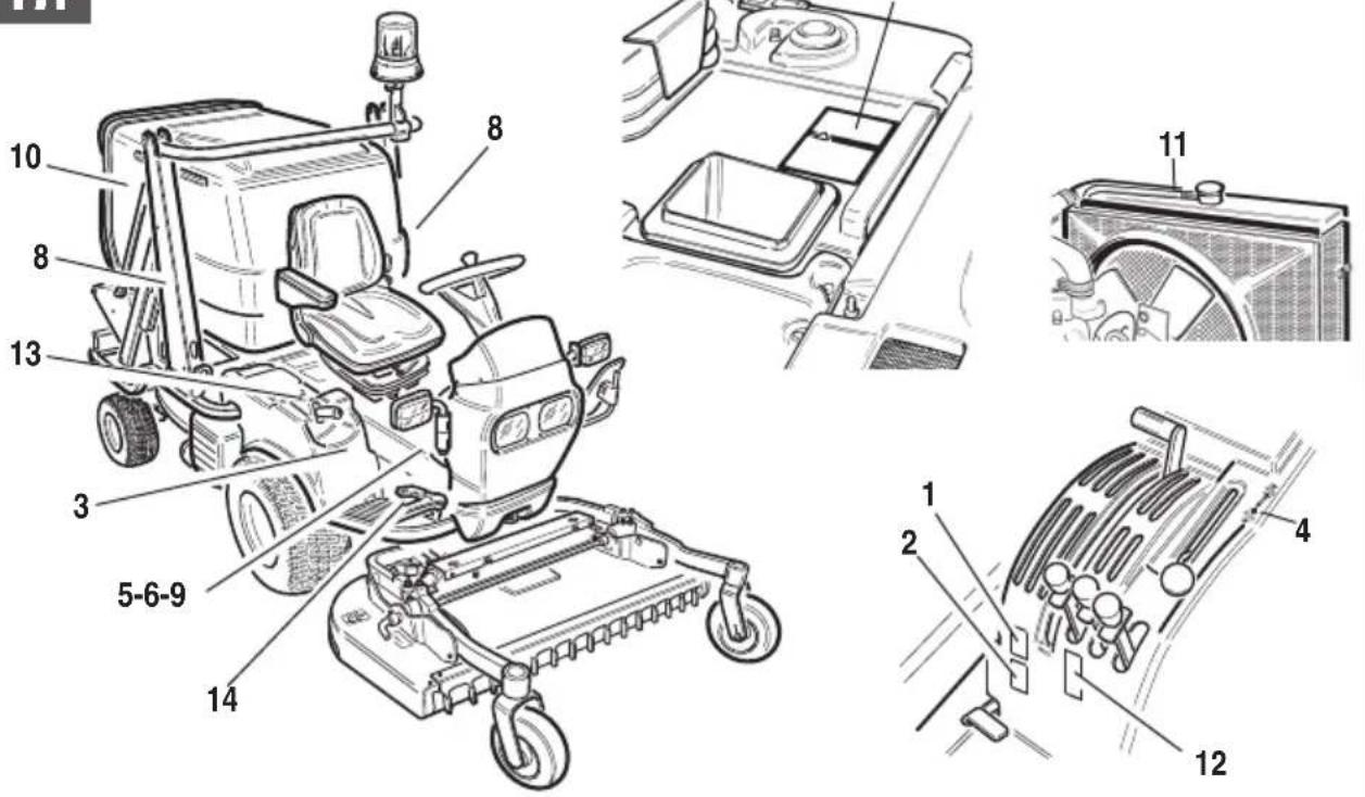
5. CONTROLS AND INSTRUMENTS
See figure 5.
The machine includes the following controls:
1) Forward speed pedal - reverse gear
2) Parking brake lever
3) Accelerator
4) Switch key
5) Nebulizer bipolar socket
6) Computer
7) P.T.O. and turbine engagement
8) Differential locking device pedal
9) Steering wheel
10) Blinker lights indicator
11) Adjusting the longitudinal seat
12) By-pass lever
13) Lights indicator
14) Light switch
15) Lever for lifting the equipment
16) Lever for overturning
basket - rubbish skip - quik grip
17) Elevator activating lever
(only elevator version)
18) Blinkers deviator
19) Emergency light switch
20) Rotating lamp switch
21) Adjusting the seat height
22) Adjusting the spring hardness

All controls described are also valid for "SR" models.
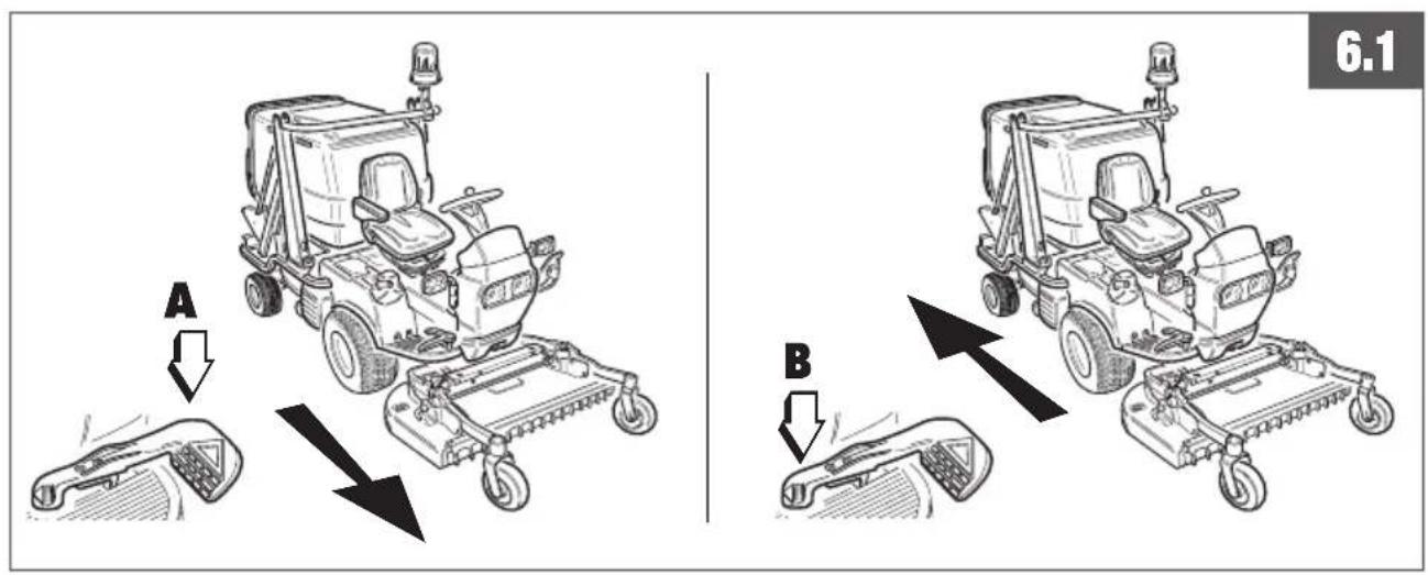
6. USING CONTROLS AND INSTRUMENTS
6.1 FORWARD - REVERSE
See figure 6.1
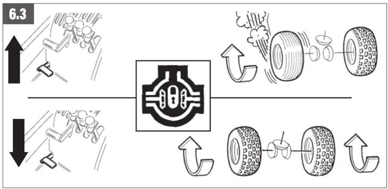
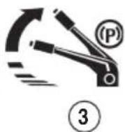
6.3 DIFFERENTIAL LOCKING DEVICE
See figure 6.3
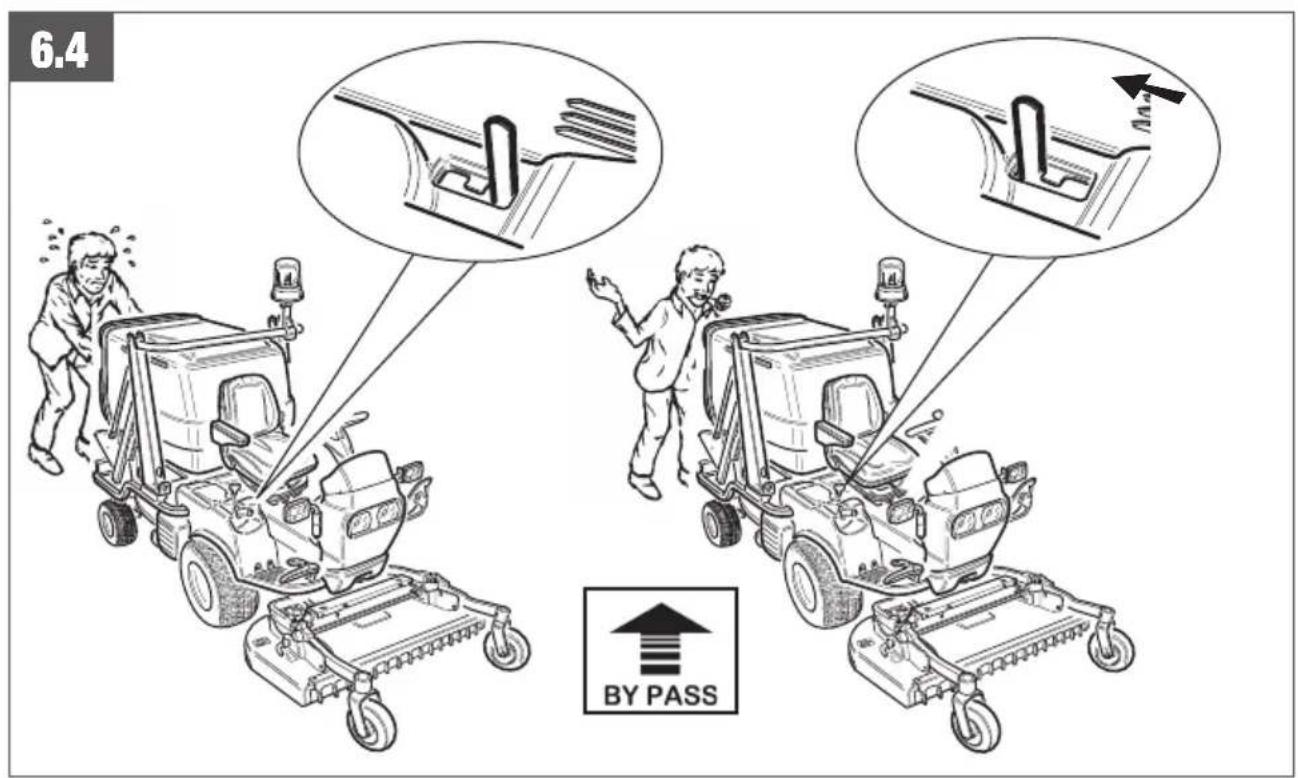
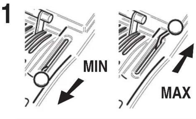
6.4 BY-PASS LEVER
See figure 6.4

IMPORTANT:
Avoid towing the machine for long stretches with inserted by-pass.
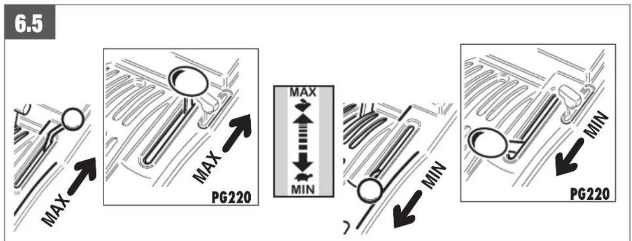
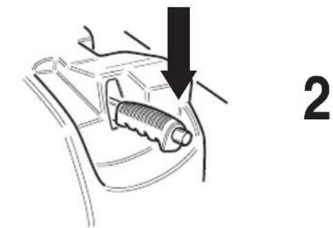
6.5 HAND THROLLE
See figure 6.5
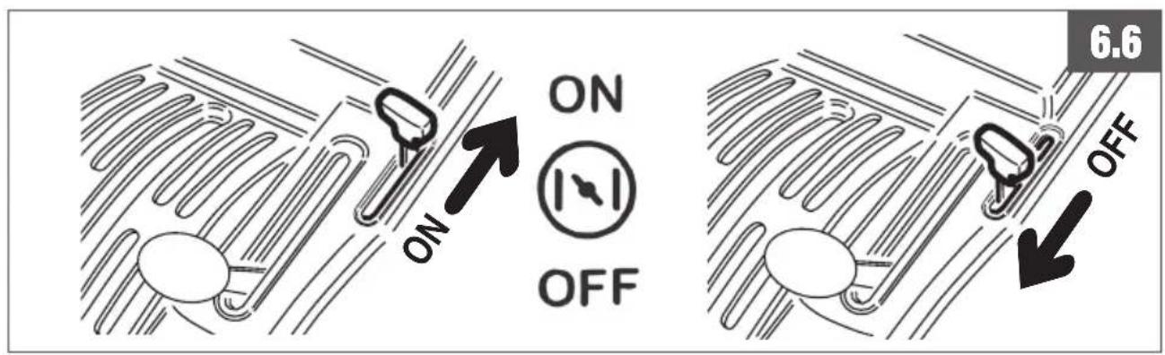
6.6 ENGINE STARTING
See figure 6.6
Only PG/SR 210 D models.
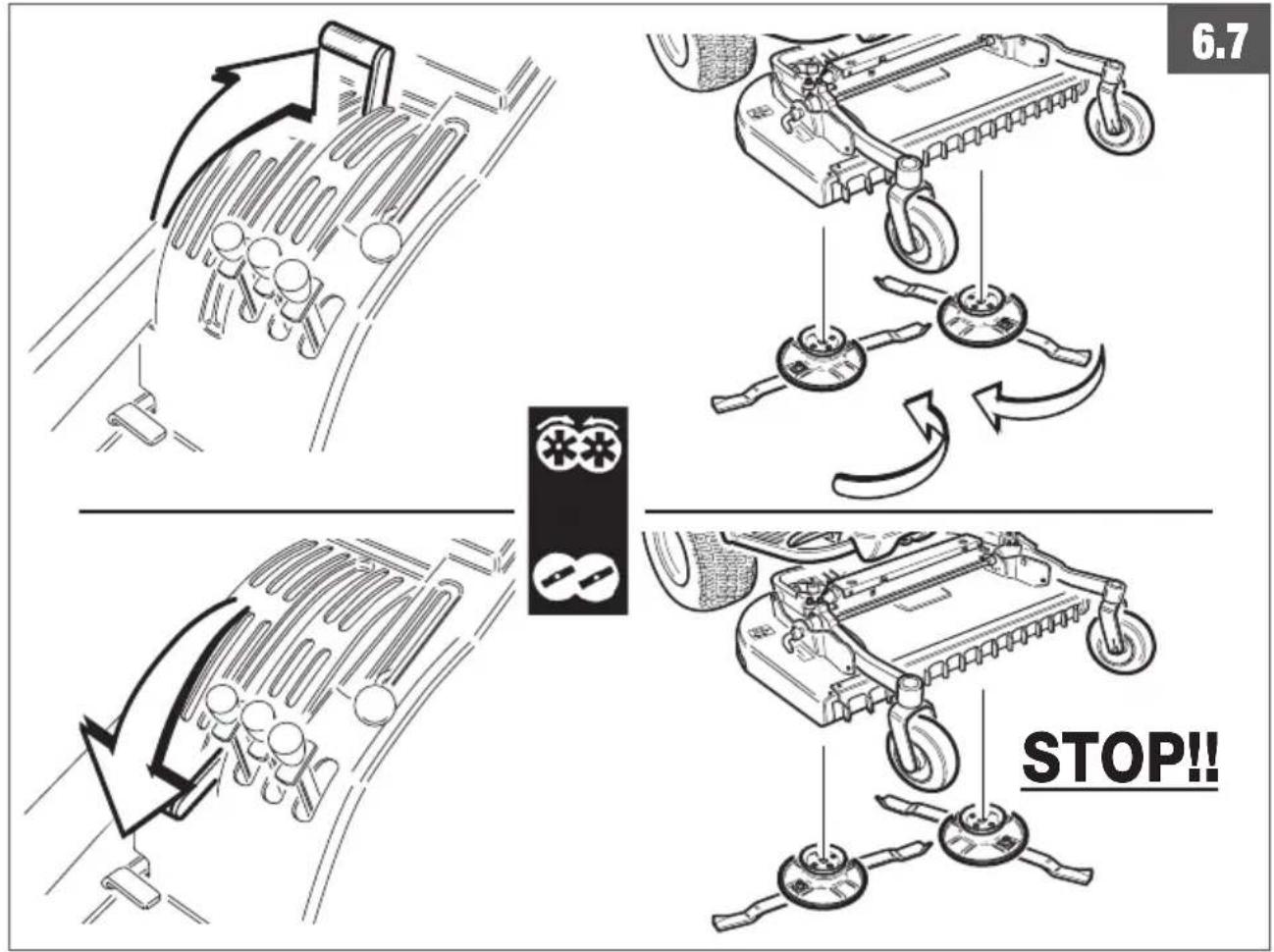
6.7 P.T.O
See figure 6.7
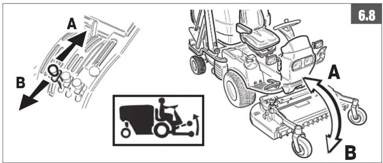
6.8 HYDRAULIC LIFT OF THE EQUIPMENT
See figure 6.8
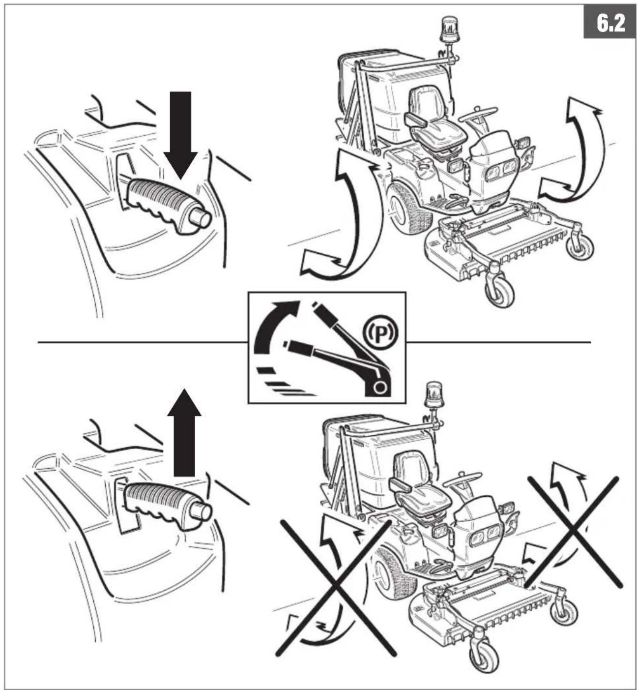
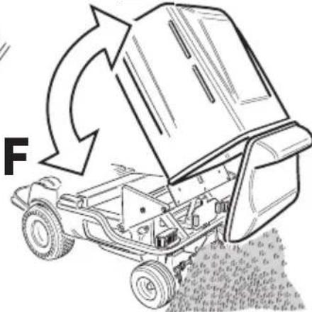
6.9 HYDRAULIC TILTING OF TRAY
See figure 6.9
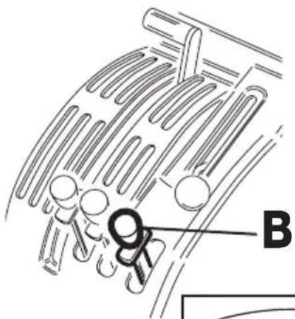
A. Basket overturning lever
B. Lever for quick grips control
6.10 ELEVATOR
See figure 6.10
A. Basket lifting lever
B. Basket overturning lever
C. Lever for quick grips control

IMPORTANT:
When trasferring the machine, especially when makin curves, do not proceed in any case with basket outside.
6.11 DESCRIPTION FUNCTIONS COMPUTER
See figure 6.11
- Motor oil pressure lamp
- Fuel reserve lamp
- Battery alternator lamp
- Parking brake inserted lamp
- Cooling fluid max temp. lamp
- Button
- Display
By pushing the button in pos. - 6 - you can:
- Visualize on the display the temperature of the radiator liquid;
- The total number of hours worked by the machine (hour counter).
The display also shows the following :
- The countdown for the pre-heating plugs (only Diesel version);
- All the error codes (see chap. 20);
- Carry out a diagnostic of the switches mounted on the machine (see chap. 7.6).

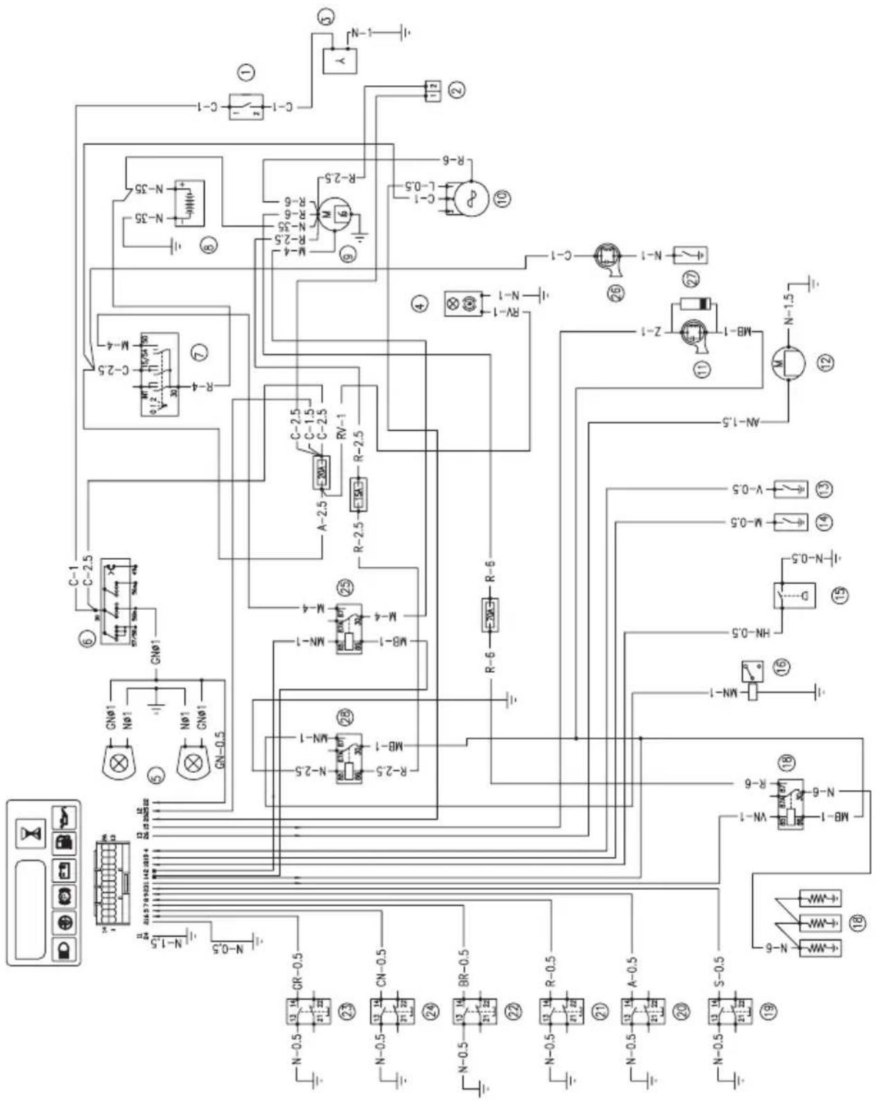
7. WIRING DIAGRAM
7.0 COLOUR PALETTE
A Orange
C Pink
E Green
G Yellow
m Brown
R Red
B White
D Grey
F Blue
h Sky-blue
N Black
V Violet
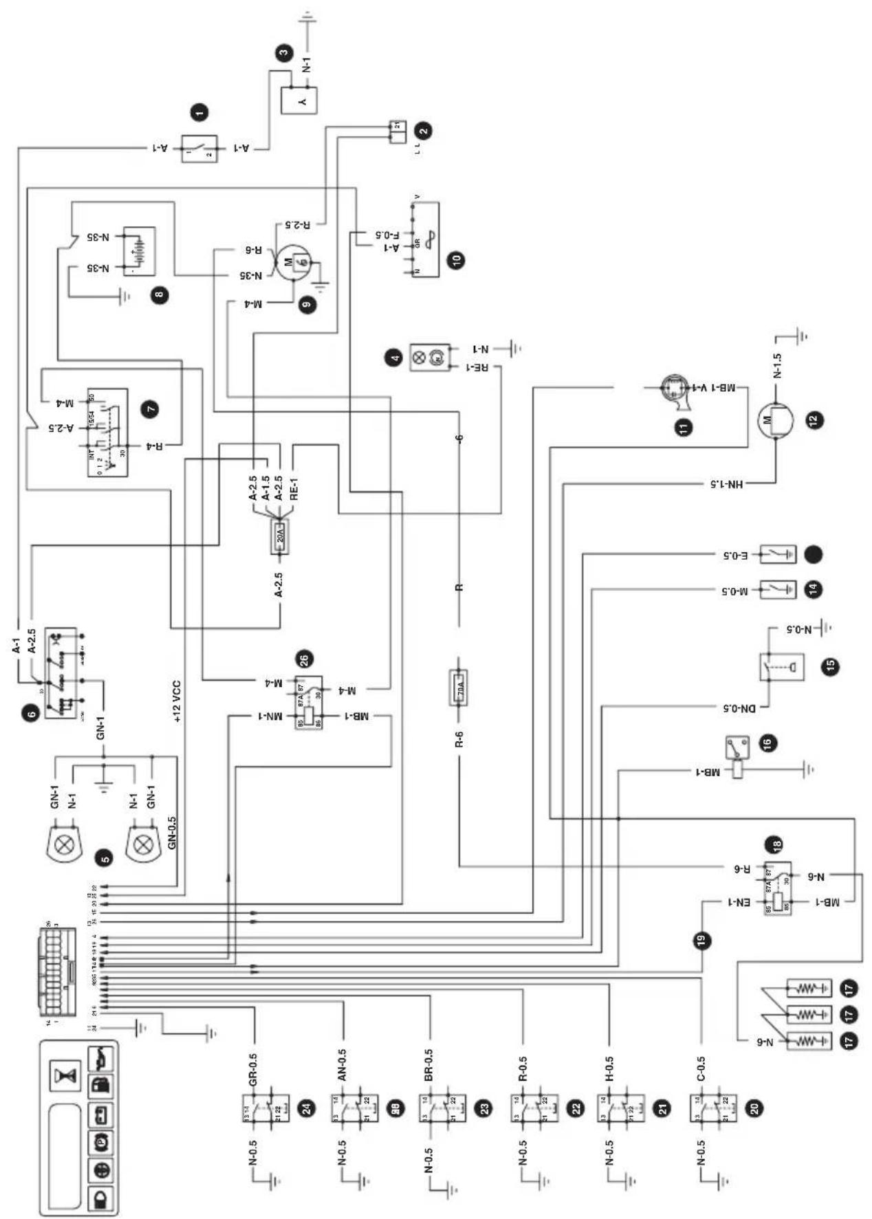
7.1 DAIHATSU 950 D
See figure 7.1
| RIF. | DESCRIPTION |
| 1 | Auxiliary socket switch |
| 2 | Road wiring supply connector |
| 3 | Auxiliary socket |
| 4 | Rotary lamp |
| 5 | Front headlights |
| 6 | Front headlights switch |
| 7 | Ignition switch |
| 8 | 12V battery |
| 9 | Motor |
| 10 | Voltage regulator |
| 11 | Buzzer |
| 12 | Leaves shaking motor |
| 13 | Water temp. sensor |
| 14 | Oil pressure sensor |
| 15 | Fuel gauge float |
| 16 | Motor stop electrovalve |
| 17 | Preheating glow-plugs |
| 18 | Prehating relay |
| 19 | Glow plugs preheating control |
| 20 | Motor compar. switch |
| 21 | Basket lifted switch |
| 22 | Seat switch |
| 23 | Parking brake switch |
| 24 | Basket full switch |
| 25 | P.T.O. lever swithc |
| 26 | Start relay |
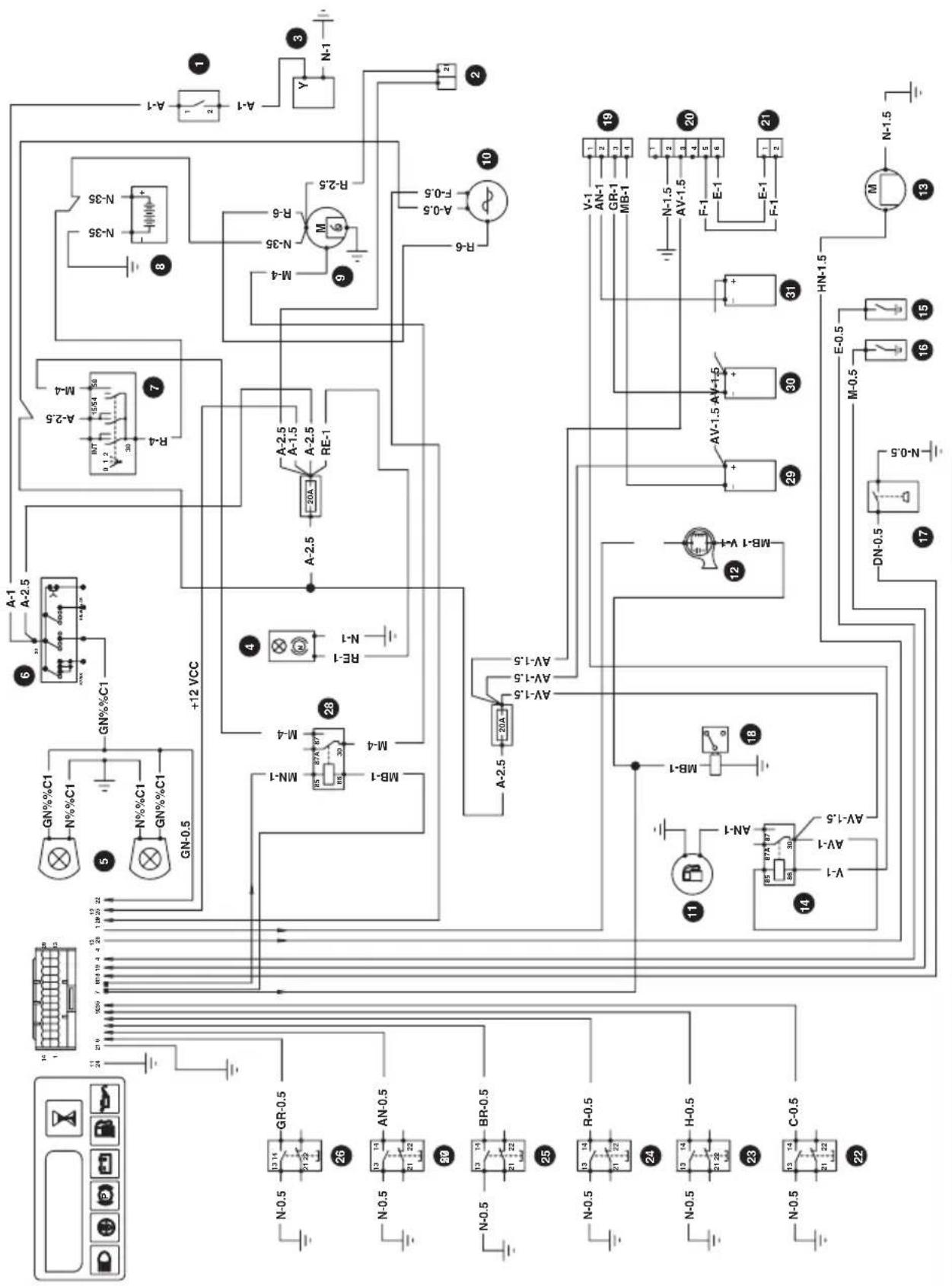
7.2 DAIHATSU 950 G
See figure 7.2
| RIF. | DESCRIPTION |
| 1 | Auxiliary socket switch |
| 2 | Road wiring supply connector |
| 3 | Auxiliary socket |
| 4 | Rotary lamp |
| 5 | Front headlights |
| 6 | Front headlights switch |
| 7 | Ignition switch |
| 8 | 12V battery |
| 9 | Motor |
| 10 | Alternator |
| 11 | Fuel pump |
| 12 | Buzzer |
| 13 | Leaves shaking motor |
| 14 | Fuel pump relay |
| 15 | Water temp. sensor |
| 16 | Oil pressure sensor |
| 17 | Fuel gauge float |
| 18 | Fuel solenoid |
| 19 | 4-way injection control unit connector |
| 20 | 6-way injection control unit connector |
| 21 | Advance |
| 22 | Motor compar. switch |
| 23 | Basket lifted switch |
| 24 | Seat switch |
| 25 | Parking brake switch |
| 26 | Basket full switch |
| 27 | P.T.O. lever switch |
| 28 | Start relay |
| 29 | Injector coil 1 |
| 30 | Injector coil 2 |
| 31 | Injector coil 3 |
COLOUR PALEttE See 7.0
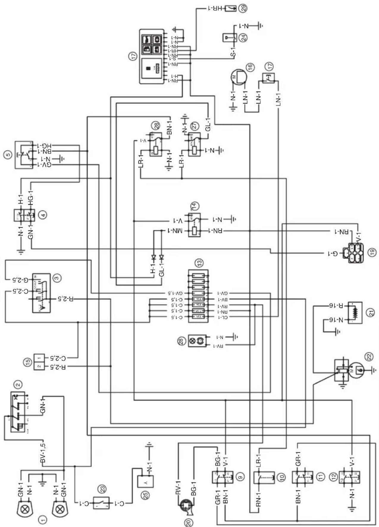
7.3 KUBOTA D 902
See figure 7.3
| RIF. | DESCRIPTION |
| 1 | Auxiliary socket switch |
| 2 | Road wiring supply connector |
| 3 | Auxiliary socket |
| 4 | Rotary lamp |
| 5 | Front headlights |
| 6 | Front headlights switch |
| 7 | Ignition switch |
| 8 | 12V battery |
| 9 | Motor |
| 10 | Voltage regulator |
| 11 | Buzzer |
| 12 | Leaves shaking motor |
| 13 | Water temp. sensor |
| 14 | Oil pressure sensor |
| 15 | Fuel gauge float |
| 16 | Motor stop electrovalve |
| 17 | Prehating glow-plugs |
| 18 | Prehating relay |
| 19 | Motor compar. switch |
| 20 | Basket lifted switch |
| 21 | Seat switch |
| 22 | Parking brake switch |
| 23 | Basket full switch |
| 24 | P.T.O. lever switch |
| 25 | Start relay |
| 26 | Hooter for max motor temp. |
| 27 | Max motor temp. sensor |
| 28 | Motor stop relay |
COLOUR PALEttE See 7.0
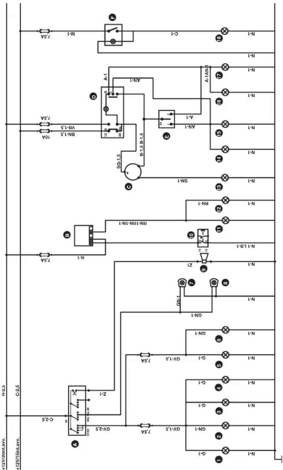
7.4 STRADALE KUBOTA D 902 DAIHATSU 950D/950G
See figure 7.4
| RIF. | DESCRIPTION |
| A | Lights / horn control |
| B | Brake lights time card |
| C | Blinking indicator lights |
| D | Emergency lights switch |
| E | Indicator lights deviator |
| F | Lamp rotating switch |
| 1 | Parking lights indicator |
| 2 | front LS parking light |
| 3 | front RS parking light |
| 4 | Plate light |
| 5 | Front RS parking light |
| 6 | Front LS parking light |
| 7 | RS dimmed headlight |
| 8 | LS dimmed headlight |
| 9 | Horn |
| 10 | Brake lights microswitch |
| 11 | Brake light |
| 12 | Brake light |
| 13 | Blinker warning light |
| 14 | Front LS blinking light |
| 15 | Rear LS blinking light |
| 16 | Front RS blinking light |
| 17 | Rear RS blinking light |
| 18 | Rotary lamp |
COLOUR PALEttE See 7.0
7.5 BRIGGS & STRATTON
See figure 7.5
RIF. DESCRIPTION
| 1 | Front working lights |
| 2 | Headlights switch |
| 3 | Engine switch |
| 4 | Parking brake switch |
| 5 | P.T.O. switch |
| 6 | Green neutral light |
| 7 | Parking brake light |
| 8 | Hourmeter |
| 9 | High basket switch |
| 10 | Seat switch |
| 11 | Full basket switch |
| 12 | Motor compar. switch |
| 13 | Fuse holder-box |
| 14 | Overload relay |
| 15 | Road wiring supply |
COLOUR PALETTE See 7.0
| 16 | Filter rotation motor |
| 17 | Pilot lamps/hourmeters |
| 18 | Generator |
| 19 | Engine stop connector |
| 20 | Hopper full buzzer |
| 21 | 12V Battery |
| 22 | Motor |
| 23 | Auxiliary socket switch |
| 24 | Fuel gauge float |
| 25 | Auxiliary socket |
| 26 | Rotary lamp |
| 27 | Seat stop relay |
| 28 | Seat stop relay with P.T.O. |
| 29 | Oil pressure sensor |

THIS SIMBOL INDICATE THE EARTH
7.6 SWITCH DIAGNOSTICS
| DISPLAY CONTROLLED SWITCH 0 - STATE 1 - STATE | |||
| P1 | PTO | OFF | ON |
| P2 | FULL BASKET | OFF | ON |
| P3 | BRAKE ENGAGED | OFF | ON |
| P4 | SEAT | OFF | ON |
| P5 | RAISED BASKET | OFF | ON |
| P6 | MOTOR COMPARTEMENT | OFF | ON |
1) Press the sand-glass key on the computer
2) Turn the ignition key on "ON"
3) Release the sand-glass key and view the first message on the display ("P1")
4) Push the relevant microswitch through the special control (see table) to check its functionality
5) Press once more the sand-glass key to check the second microswitch ("P2")
6) Proceed as described at points 4) and 5) to check the remaining microswitches
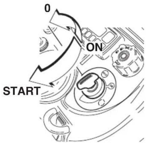
8. STARTING THE ENGINE
See figure 8.
1) Take your place correctly on seat.
2) Make sure that P.T.O. lever is entirely disengage
3) Make sure that the parking brake lever in enturely engaged
4) Turn the ignition key to the "ON" position and wait until the glow plugs are preheated, if necessary
5) Turn the ignition key onto the symbol to start the motor
6) With temperature under 0^ C keep the motor at medium speed for at least 5 minutes
9. DRIVING THE MACHINE
See figure 9.
1) Set throttle lever.
2) Disengage the parking brake.
3) Select the desired speed though the pedal fitted on the right side.
4) By moving the steering wheel one steers the back wheel.
N.B.: To stop the machine, just release the forward or reverse pedal; once stopped, pull the parking brake lever.

IMPORTANT: To being drive at slow speed, for safety reasons make sure that people and animals are at least 3 meters away
10. CUTTING AND AUTOMATIC GRASS COLLECTION
See figure 10.
11. STOPPING THE MOTOR
See figure 11.
1) Stop the machine.
2) Declutch the PDP lever.
3) Pull the parking brake lever.
4) Full lower the equipment by means of the specific lever.
5) Make sure that the basket is completely draw in.
6) Reduce the motor revolution on minimum.
7) Turn the ignition key from "ON" position to "STOP" position.
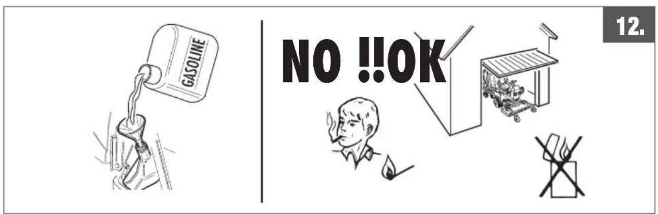
12. TANK FILLING
See figure 12.
Only fill the tank in open air or in a sufficiently ventilated room. The engine must be turned off and no flames or sparks should be made. Check that carburant is the one indicated by the label on the tank.
WARNING: CARBURANT IS HIGHLY INFLAMMABLE.
KEEP THE CARBURANT IN JERRYCANS. FILL THE TANK WITH PETROL ONLY IN OPEN AIR AND DO NOT SmOkE DURING this OPERATION. ADD CARBURANT BEFORE STARTING the ENGINE. NEVER REMOVE THE TANK LID NOR ADD CARBURANT WHEN THE ENGINE IS WORKING OR IS HOT.
In case of carburant escape, do not try to start the engine but move the machine away from the place where the escape took place and avoid creating ignition sources until carburant fumes have dissipated. Replace the correct lids on the tank and the jerrycan. Never store the machine with carburant in the tank inside a building where the fumes might reach some free flames or sparks.
Let the engine cool down before storing the machine in any closed environment.
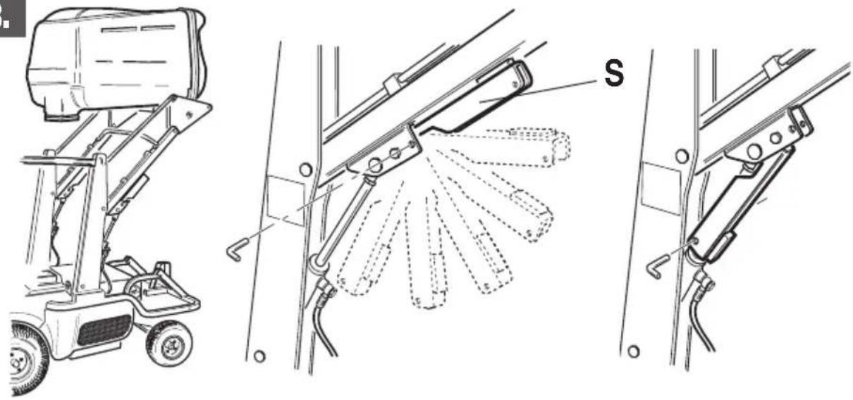
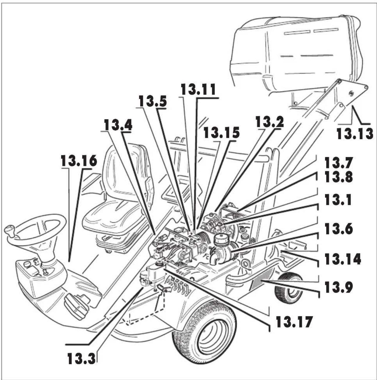
13. ORDINARY MAINTENANCE
See figure 13.
If you have to carry out maintenance operations, use only original spare parts, to ensure the same maximum reliability to the machine. Before carrying out any maintenance work, read carefully the indications given in the paragraph 3 “Safety rules”. In case you have to intervene on the machine with lifted basket, make sure that the mechanical lock “S” is correctly engaged.
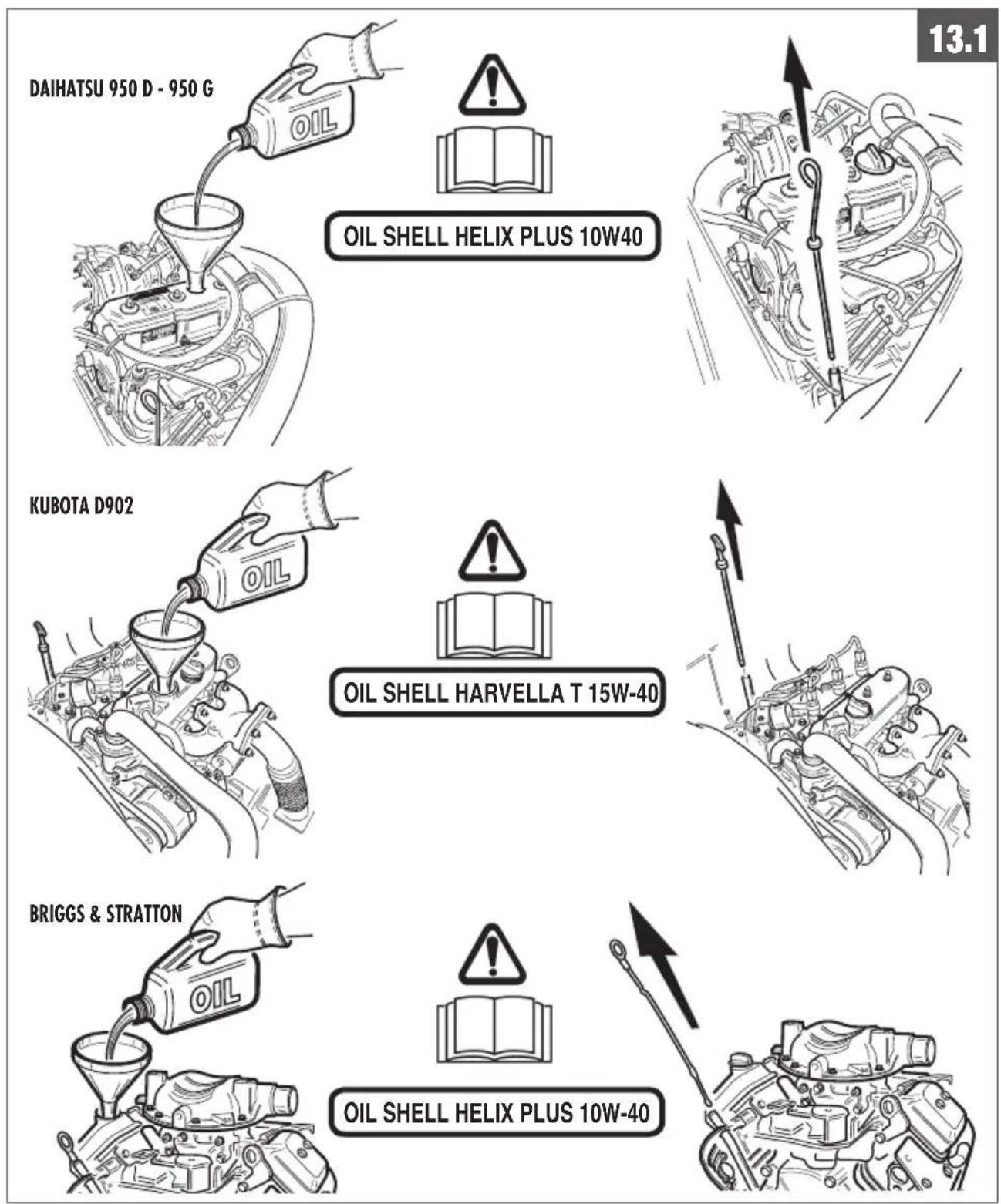
13.1 ADD MOTOR OIL
See figure 13.1
• DAIHATSU 950 D - 950 G
Consult the Use and Maintenance manual of the motor.
OIL SHELL HELIX PLUS 10W40
• KUBOTA D 902
Consult the Use and Maintenance manual of the motor.
OIL SHELL HARVELLA T 15W-40
• BRIGGS & STRATTON 22 HP W-TWIN
Consult the Use and Maintenance manual of the motor.
OIL SHELL x 200 SAE 30
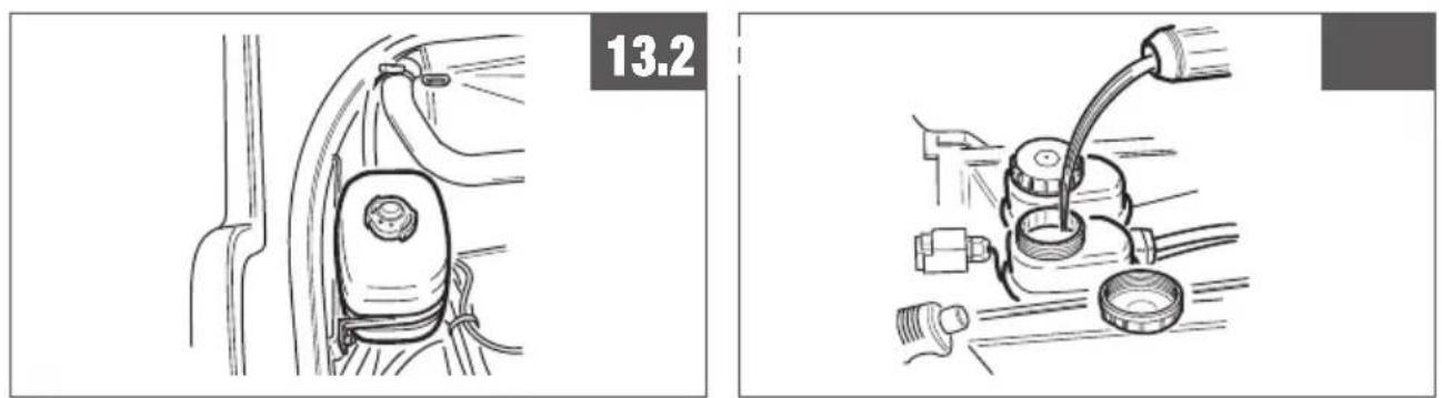
13.2 ADD COOLING FLUID
See figure 13.2
Not present on model PG220.
13.3 ADD HYDRAULIC SYSTEM OIL
See figure 13.3
OIL SHELL HARVELLA T 15W-40
13.4 ADD FRON AXIAL OIL
See figure13.4
OIL SHELL HARVELLA T 15W-40
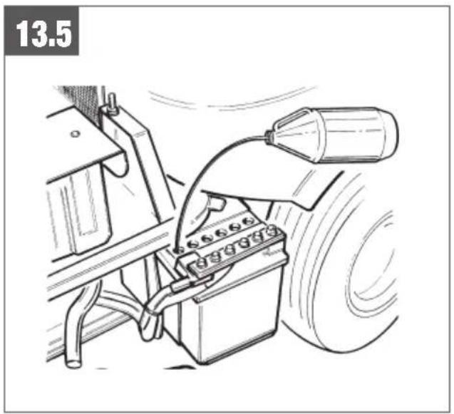
13.5 BATTERY
See figure13.5
Check periodically the electrolyte level and, if necessary, add distilled water, checking the level indicated on the battery body.
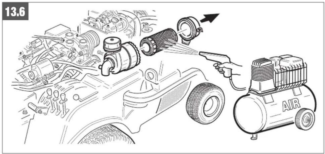
13.6 AIR FILTER
See figure 13.6
Periodical checks.

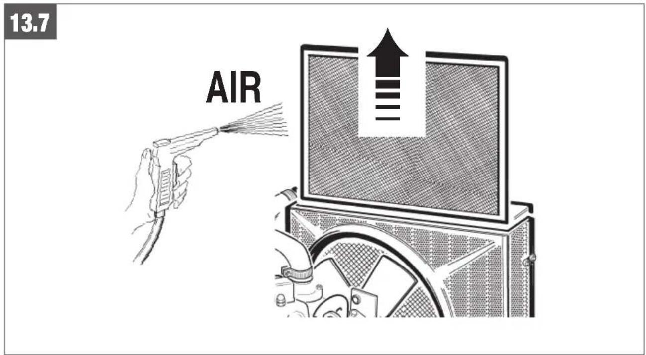
13.7 RADIATOR NET
See figure 13.7
Periodical cheks.
Not present on model PG220.
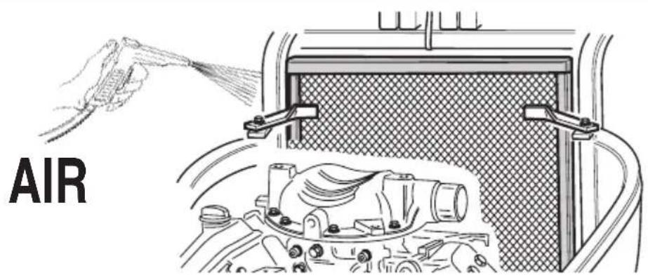
13.8 MOTOR NET
See figure 13.8
Periodical checks.
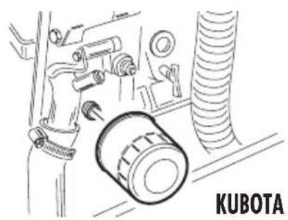
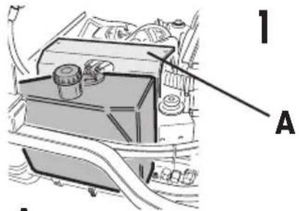
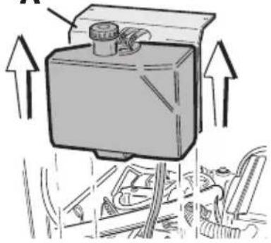
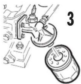
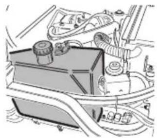
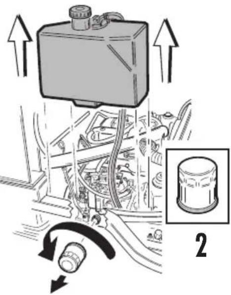
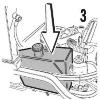
13.9 MOTOR OIL FILTER
See figure 13.9
Consult the use and maintenance manual of the motor.

Remove the bulkhead A, before maintaining the motor oil filter.
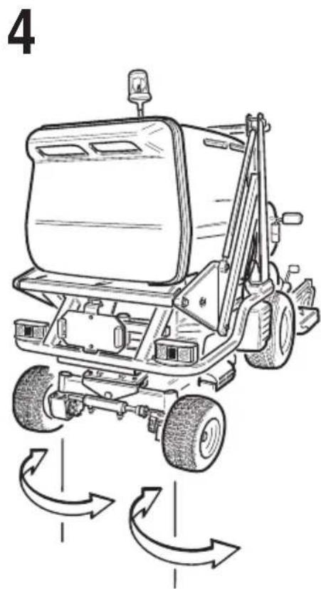
13.10 TYRE PRESSURE
See figure 13.10
If the front tires are inflated at different pressure, the blades will mow the grass at different heights
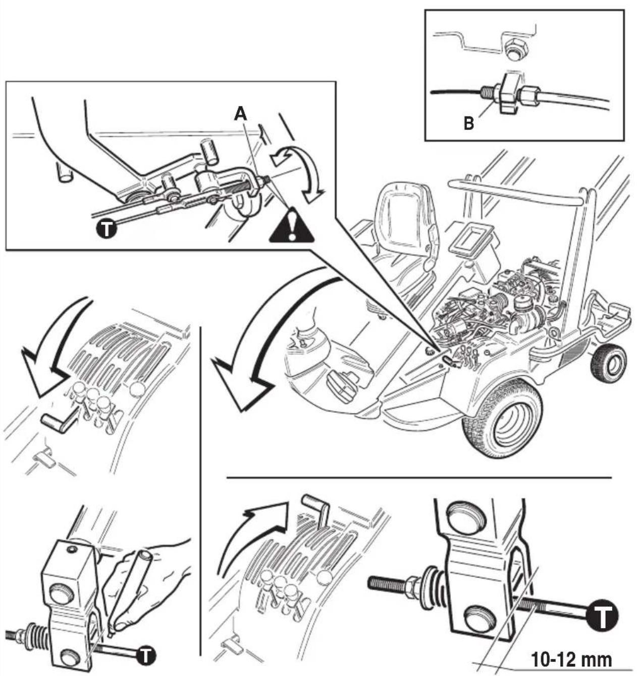
13.11 BELT TENSION ADJUSTEMENT
See figure 13.11
- After the first 5÷10 hours of work, adjust the P.T.O. belts tension:
1) Fully disengage the P.T.O. and mark with a felt-tip the position of tie-rod T.
2) Insert the P.T.O. and check if the value marlek is 10-12 mm. If it is different, act on the relevant screw A and to the screw B.

Pay attention to the dimensions of the eye of the cylinder.
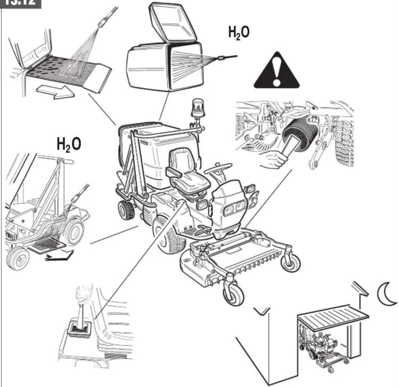
13.12 CLEANING THE MACHINE
See figure 13.12
13.13 BASKET OVERTURN, CYLINDER GREASE NIPPLE
See figure 13.13
With elevator.
13.14 BASKET OVERTURN, CYLINDER GREASE NIPPLE
See figure 13.14
Without elevator.
13.15 PDP GREASE NIPPLE
See figure 13.15
13.16 PEDAL GREASING
See figure 13.16
See tab. maintenance.
13.17 HYDRAULIC INSTALLATION FILTER
See figure 13.17
14. EXTRAORDINARY MAINTENANCE
For the extraordinary maintenance of the machine, contact only an authorised service center.
15. INACTIVITY OF MOWER DECK
In case the PG-SR lawnmower has to remain idle for a long period of time, it is convenient to carry out some operations to ensure its efficiency when reused and the duration of the same for years:
-Disconnect the equipment from the engine and follow the operations indicated in the relevant use and maintenance manual to prearrange it for “out of service”.
-Carry out all the indications given in the use and maintenance manual of the motor prearrange the same for "out of service".
-Remove the battery, recharge it and store it in a dry and ventilated place.
-Clean carefully the engine with an eye in particular where there are incrustations due to soil and grass residues.
-Carry out the of “ordinary maintenance” operations described above and, if necessary, carry out also the “extraordinary maintenance”.
-Park the engine in a dry and ventilated place and cover it with a suitable non-impermeable protection sheet.
-During the period of inactivity, always maintain the pressure indicated for the tyres and, periodically, change the resting point of the tyres on the ground.
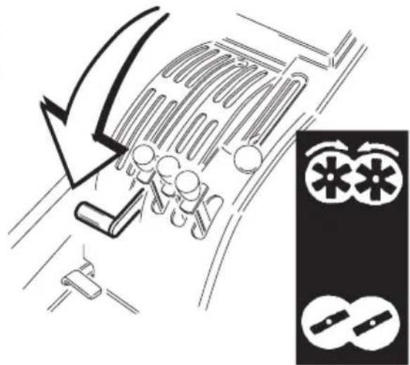
16. ROAD TRANSPORT
See figure 16.
The PG-SR lawnmowers, since they are accompanied by road approval certificate(*), have the possibility of circulating on public roads provided the following rules are observed:
-The lawnmower must obligatorily be accompanied by a regular registration, a registration document (log book), a correctly mounted number plate and an insurance against road accidents (car liability insurance).
-The driver of the lawnmower must carry a regular driving licence (at least, type B).
-The lighting installation and the braking devices of the lawnmower must be correctly operating and in perfect efficiency.
-All the lighting devices must be fully visible. Please keep in mind that the rotating lamp device (blinker) must always be on, even during day time.
-The PG-SR lawnmower can circulate with and without the equipments attached ( ^** ). When circulating on a road without equipment, it is recommended to keep the front arms of the 2-point attachment on the engine fully lifted. When the road trasfer is made with equipment connected, it is obligatory to keep the same entirely lifted and fastened to the machine body by means of the mechanical lock.
-The machine, in its front part, is fitted with a tow bar that can be exploited in case of troubles with the lawn-mower.
-The technical limits and conditions expressly indicated in the registration document of the lawnmower must always be respected.
-As to the road traffic rules, the standard Rules of the Road apply.
(*): Only for the versions where this is foreseen.
(**): The equipments that can equip the lawnmower during road circulation are expressly indicated in the registration document.

Before travelling on the road opened to traffic, you should become familiar with all the controls of the machine.
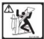
17. SAFETY STICKERS
See figure 17.
18. NOTES
A) Please contact our authorised dealer for anything that is not dealt with in this manual.
B) Always keep this technical handbook in a safe place for future reference. It can be modified without prior notice or any additional obligations in order to improve the product. Reproduction or translation of any part of this manual is not allowed without the owner's prior written consent.
19. TABLE MAINTENANCES
| hOURS MAIN MAINTENANCE OPERATIONS | 5 10 | 30 50 | 100 200 | 400 | 500 | NOTES | |||
| MOTOR INTAKENET CLEANING | X + | ||||||||
| BELT CHECK | X+++ | X | |||||||
| HOPPER GRID CLEANING | X + | ||||||||
| HYDRAULIC GRID CLEANING | X | = | |||||||
| BLADE SHARPENING | X + | ||||||||
| OVERHALL CLEANING | X | = | |||||||
| ACCURATE GENERAL CLEANING | X | = | |||||||
| GREASING | X | ||||||||
| WHEEL TRANSM. OIL LEVEL | X | ||||||||
| TRAMS. AMD MOWER OIL LEVEL | X | ||||||||
| HYDROST. DRIVE AND HYDRAULIC SYST. OIL LEVEL | X | ||||||||
| SAUER TRANSMISSION OIL CHANGE | X | + | |||||||
| AIR FILTER CLEANING | X + | ++ | |||||||
| MOTOR OIL LEVEL | X + + | ||||||||
| MOTOR OIL CHANGE | X+++ | X + + | |||||||
| MOTOROIL FILTER CARTRIDGE CHANGE | X+++ | X + + | |||||||
| CARBURATEUR FILTER CHANGE | X + + | ||||||||
| AIR FILTER CHANGE | X + | ++ | |||||||
| COOLING LIQUID LEVEL | X + + | ||||||||
| COOLING LIQUID CHANGE | X + + | ||||||||
| MOTOR MAINTENANCE | X + + | ||||||||
| CHANGING HYDRAULIC INSTALL. FILTERS | X |
-
In case of particularly heavy working conditions, these operation must be carried more frequently.
++ Motor maintenance: check themotor operating and maintenance manual.
+++ Initial change - initial adjustment.
= These cleaning operations must be carried out preferably with compressed air. Avoid using water. -
ERROR CODE DISPLAY
| ERROR ERROR POSITION CODE | BUZZER ALARM DESCRIPTION | POSSIBLE CAUSES LENGTH OF AND/OR REMEDIES SIGNAL | ERROR | |||
| Initial test phase | E1 lamp | The test on the pre-heating sensor has detected a lower temperature than the envisaged range. | The pre-heating sensor has probably not been activated correctly. | Until the error condition is removed. | 1 | |
| E2 lampthan the envisaged range. | The test on the pre-heating sensor has detected a lower temperature correctly. | The pre-heating sensor has probably not been activated | Until the error condition is removed. | 1 | ||
| E3 lamp | The test on the water temperature sensor has detected a higher temperature than the range. | The water temperature sensor has probably not been activated correctly. | Until the error condition is removed. | 2 | ||
| E4 lamp | The test on the water temperature sensor has detected a lower temperature than the range. | The water temperature sensor has probably not been activated correctly. | Until the error condition is removed. | 2 | ||
| Glow plug heating cycle | E10 | The safety test has found the PTO activated. | Disconnect the PTO. | Until the error condition is removed. | 1 | |
| E11 | The safety test has found the parking brake is off. | Apply the parking brake. | Until the error condition is removed. | 2 | ||
| E12 | The safety test has found the driver is not in his seat. | The driver must sit on the seat. | Until the error condition is removed. | 3 | ||
| E14engine compartment open. | The safety test has found the | Close the engine compartment is removed. | Until the error condition | 5 | ||
| Operating cycle | E20 | The safety test has found the PTO activated. | Disconnect the PTO.switched back on. | Until the error condition is removed and the engine | 1 | |
| E21 | The safety test has found the parking brake is off. | Apply the parking brake.switched back on. | Until the error condition is removed and the engine | 2 | ||
| E22 | The safety test has found the man is not in his seat. | Sit on the seat.switched back on. | Until the error condition is removed and the engine | 3 | ||
| E24engine compartment open. | The safety test has found the | Close the engine compartment is removed and the engine switched back on. | Until the error condition | 5 | ||
| Lamptemp.exceeded the temperature of 100°C. | Beeps | The water temperature test has found that the engine has | Disengage PTO and keep motor at medium speed. | Until temperature returns normal. | 6 | |
| E30beeps | Very slow | The basket is full and the PTO activated. | Until you quit the alarm condition. | 7 | ||
| E31 | Slow beeps | The air filter is clogged. | Until you quit the alarm condition. | 7 | ||
| Any phase | CC1 | There is a short circuit on the glow plug heating output. | Check the glow plug heating circuit.switched back on. | Until the error condition is removed and the engine | 0 | |
| CC2 | There is a short circuit on the engine stop output. | Check the engine stop circuit.switched back on. | Until the error condition is removed and the engine | 0 | ||
| CC3 | There is a short circuit on the buzzer output. | Check the buzzer circuit.switched back on. | Until the error condition is removed and the engine | 0 |

SOMMAIRE
NOTES POUR L'ÉLIMINATION DU PRODUIT, VALABLES POUR LA COMMUNAUTÉ EUROPÉENNE ..... 34
-
PLAQUE CE....35
-
A NOS CLIENTS 35
-
RESPONSABILITE DU CONDUCTEUR 35
-
NORMES DE SECURITE 35
3.1 PENTES 36
3.2 TRANSPORT ET DÉCHARGEMENT 36
- CARACTERISTIQUES TECHNIQUES 37
4.1 CARACTERISTIQUES TECHNIQUES 37
4.2 APPARAT TONDEUSE/ ÉQUIPEMENT 38
4.3 NIVEAU DE PUISSACE ACOUSTIQUE....38
4.4 OPERATEUR 38
-
COMMANDES 38
-
UTILISATION COMMANDES ET INSTRUMENTS....39
6.1 AVANCEMENT-MARCHE ARRIERE 39
6.2 LEVIER FREIN DE STATIONNEMENT 39
6.3 BLOC DIFFERENTIEL 39
6.4 LEVIER BY-PASS 39
6.5 ACCELERATEUR MANUAL 39
6.6 DEMARRAGE DU MOTEUR 39
6.7 PRISE DE FORCE 39
6.8 SOULÉVEMENT HYDRAULIQUE DE L'APPAREILLAGE 39
6.9 RENVERSEMENT HYDRAULIQUE DU BAC 39
6.10 ELEVATEUR 39
6.11 DESCRIPTION FONCTIONNE COMPUTER 39
- SCHEMA ELECTRIQUE....40
7.0 PALETTE DES COLEURS 40
7.1 DAIHATSU 950 D 40
7.2 DAIHATSU 950 G....40
7.3 KUBOTA D 902 41
7.4 STRADALE KUBOTA D 902 DAIHATSU 950D/950G 41
7.5 BRIGGS & STRATTON 42
7.6 DIAGNSTIC SUR LES INTERRUPTEURS....42
-
DEMARRAGE DU MOTEUR 42
-
UTILISATION DE LA MACHINE 43
-
COUPE DE L'HERBE ET SYSTEME DE RAMASSAGE AUTO 43
-
ARRET DU MOTEUR 43
-
REMPLISSAGE RESERVOIR 43
-
ORDINAIRE ENTRETIEN 43
13.1 REMPLISSAGE HUILE MOTEUR....43
13.2 REMPLISSAGE LIQUID REFRIGERANT 44
13.3 REMPLISSAGE HUILE INSTALLATION HYDRAULIQUE 44
13.4 REMPLISSAGE HUILE AXIAL ANTERIEUR 44
13.5 BATTERIE....44
13.6 FILTRE AIRE 44
13.7 FILET RADIATEUR 44
13.8 FILET MOTEUR....44
13.9 FILTRE HUILE MOTEUR 44
13.10 PRESSION PNEUS 44
13.11 RÉGLAGE TENSION COURROIES 44
13.12 NETTOYAGE DE LA MACHINE....44
13.13 GRAISSEUR VERIN BASCUL CORBEILLE 44
13.14 GRAISSEUR VERIN BASCUL CORBEILLE 44
13.15 GRAISSEUR PDP 44
13.16 GRAISSAGE PÉDALE 44
13.17 FILTRES INSTALLATION HYDRAULIQUE 44
-
ENTRETIEN EXTRAORDINAIRE 45
-
INACTIVITÉ DE LA TONDEUSE....45
-
CIRCOLATION ROUTIÉRE 45
-
ETIQUETTES DE LA SECURITE 45
-
INFORMATIONS GENERALES 46
-
OPERATIONS PRINCIPALES D'ENTRETIEN....46
-
AFFICHAGE DES CODES D'ALARM 47
NOTES POUR L'ÉLIMINATION DU PRODUIT, VALABLES POUR LA COMMUNAUTÉ EUROPÉENNE

c) freinage insuffisant;
6.5 ACCELERATEUR MANUAL Voir figure 6.5
6.6 DEMARRAGE DU MOTEUR Voir figure 6.6
Only PG/SR 210 D models.
6.7 PRISE DE FORCE Voir figure 6.7
6.8 SOULÉVEMENT HYDRAULIQUE DE L'APPAREILLAGE Voir figure 6.8
6.9 RENVERSEMENT HYDRAULIQUE DU BAC Voir figure 6.9
6.3 DIFFERENTIALSPERRE....53
13.16 SM∅RING AF PEDAL 86
13.17 HYDRAULIK INSTALLATION FILTER....86
-
YDERLIGERE VEDLIGEHOLDELSE 86
-
VINTEROPBEVARING 86
-
TRANSPORT 86
-
SIKKERHEDSMAERKATER 87
-
BEMÆRKNINGER 87
-
VEDLIGEHOLDELSESTABEL 87
-
FEJLKODEDISPLAY 88
NOTER OM BORTSKAFFELSE AF PRODUKTET GÄLDENDE FOR DET EUROPÆISKE FÄLLESSKAB
13.3 PÅFYLDNING AF HYDRAULIKOLIE
OIL SHELL HARVELLA T 15W-40
Se figur 13.3
13.4 PÅFYLDNING AF OLIE TIL FRONTAKSEL
OIL SHELL HARVELLA T 15W-40
Se figur 13.4
13.5 BATTERI Se figur 13.5
13.16 SM∅RING AF PEDAL
Se figur 13.16
Se vedligeholdelsestabel.
13.17 HYDRAULIK INSTALLATION FILTER
Se figur 13.17
14. YDERLIGERE VEDLIGEHOLDELSE
DIT SYMBOOL GEEFT DE AARDE AAN
7.6 DIAGNOSE
| DISPLAY | GECONTROLEERDE SCHAKELAAR 0 - STATUS 1 - STATUS | ||
| P1 AFTAKAS UIT AAN | |||
| P2 CONTAINER (VOL) UIT AAN | |||
| P3 REM INGESCHAKELD UIT AAN | |||
| P4 ZITTING UIT AAN | |||
| P5 | GEHEVEN CONTAINER | UIT AAN | |
| P6 | MOTOR COMPARTIMENT SCHAKELAAR | UIT AAN |
13.7 RADIATEUR BESCHERMINGS GAAS
Zie cijfer 13.7
13.8 MOTOR BESCHERMINGS GAAS
Zie cijfer 13.8
ILLUSTRATIONS AND DIAGRAMS
natural_image
Line drawing of a tractor with no visible text or symbols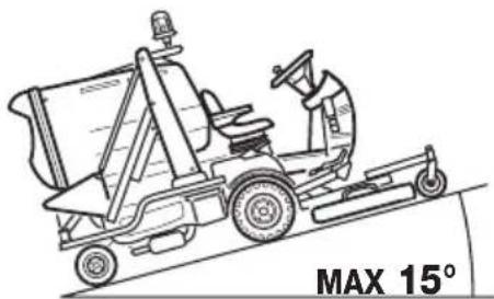
natural_image
Line drawing of a robotic car with a worker operating it, labeled MAX 15° (no other text or symbols)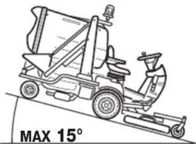
natural_image
Line drawing of a robotic car with a steering wheel and driver, labeled MAX 15° (no other text or symbols)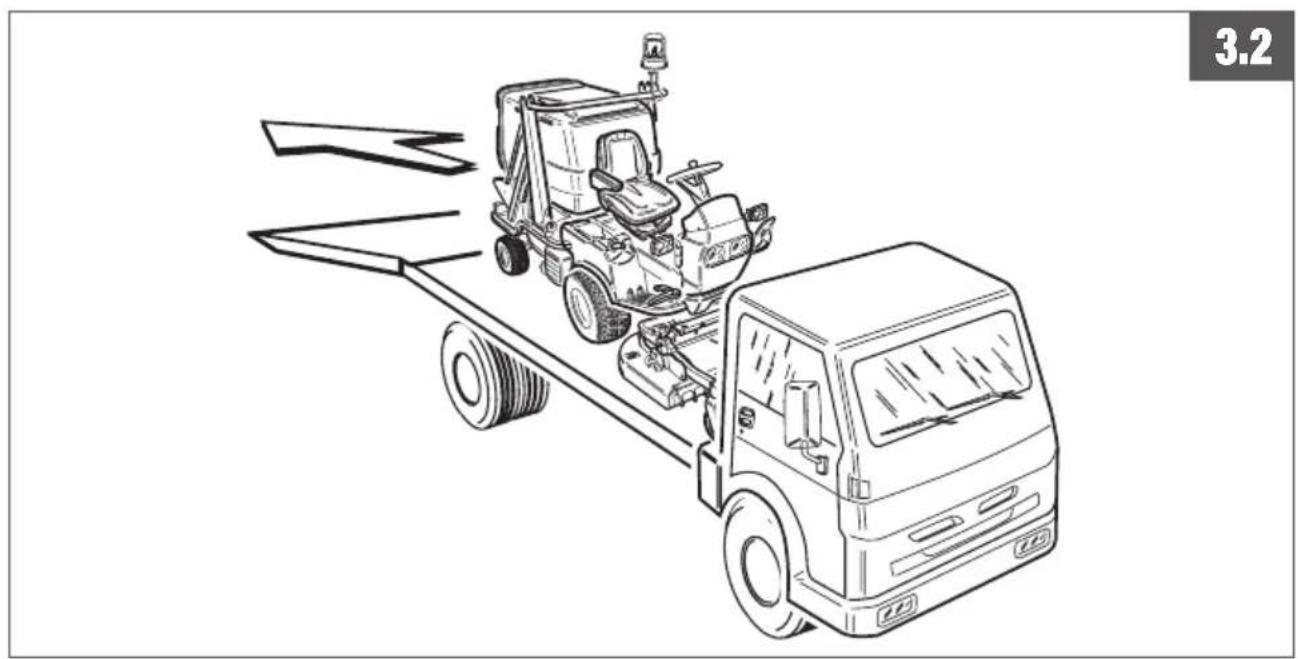
natural_image
Line drawing of a tractor on a flatbed truck, no text or symbols present
natural_image
Technical line drawing of a mechanical component with labeled part '2' (no text or symbols on the diagram itself)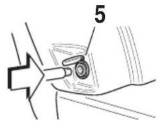
flowchart
graph TD
    A["Top: Tire Mount"] --> B["Bottom: Tire Belt"]
    B --> C["Left: Internal Combustion Engine"]
    B --> D["Right: Internal Combustion Engine"]
    style A fill:#f9f,stroke:#333
    style B fill:#ccf,stroke:#333
    style C fill:#cfc,stroke:#333
    style D fill:#fcc,stroke:#333
6.9

E
natural_image
Diagram of a vehicle with an open trunk and a large block being lifted by a curved arrow, no text or symbols present.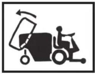
natural_image
Silhouette of a forklift carrying a large rectangular object, with motion arrows indicating rotation (no text or symbols)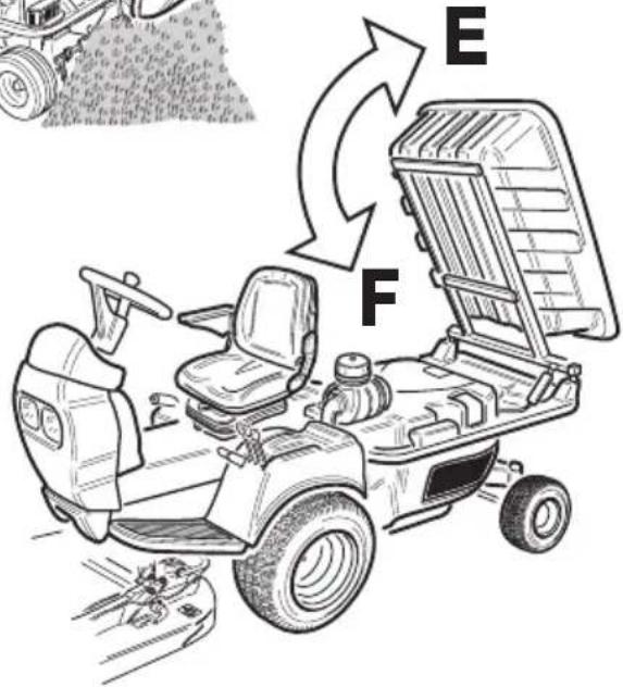
natural_image
Line drawing of a motor and steering wheel assembly (no text or symbols)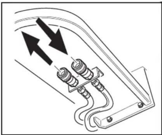
natural_image
Pure electrical circuit lines without any symbols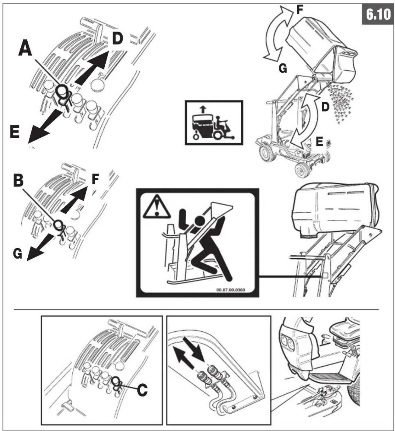

7.1 DAIHATSU 950 D
flowchart
graph TD
    A["1"] --> B["2"]
    B --> C["3"]
    C --> D["4"]
    D --> E["5"]
    E --> F["6"]
    F --> G["7"]
    G --> H["8"]
    H --> I["9"]
    I --> J["10"]
    J --> K["11"]
    K --> L["12"]
    L --> M["13"]
    M --> N["14"]
    N --> O["15"]
    O --> P["16"]
    P --> Q["17"]
    Q --> R["18"]
    R --> S["19"]
    S --> T["20"]
    T --> U["21"]
    U --> V["22"]
    V --> W["23"]
    W --> X["24"]
    X --> Y["25"]
    Y --> Z["26"]
    Z --> AA["27"]
    AA --> AB["28"]
    AB --> AC["29"]
    AC --> AD["30"]
    AD --> AE["31"]
    AE --> AF["32"]
    AF --> AG["33"]
    AG --> AH["34"]
    AH --> AI["35"]
    AI --> AJ["36"]
    AJ --> AK["37"]
    AK --> AL["38"]
    AL --> AM["39"]
    AM --> AN["40"]
    AN --> AO["41"]
    AO --> AP["42"]
    AP --> AQ["43"]
    AQ --> AR["44"]
    AR --> AS["45"]
    AS --> AT["46"]
    AT --> AU["47"]
    AU --> AV["48"]
    AV --> AW["49"]
    AW --> AX["50"]
    AX --> AY["51"]
    AY --> AZ["52"]
    AZ --> BA["53"]
    BA --> BB["54"]
    BB --> BC["55"]
    BC --> BD["56"]
    BD --> BE["57"]
    BE --> BF["58"]
    BF --> BG["59"]
    BG --> BH["60"]
    BH --> BI["61"]
    BI --> BJ["62"]
    BJ --> BK["63"]
    BK --> BL["64"]
    BL --> BM["65"]
    BM --> BN["66"]
    BN --> BO["67"]
    BO --> BP["68"]
    BP --> BQ["69"]
    BQ --> BR["70"]
    BR --> BS["71"]
    BS --> BT["72"]
    BT --> BU["73"]
    BU --> BV["74"]
    BV --> BW["75"]
    BW --> BX["76"]
    BX --> BY["77"]
    BY --> BZ["78"]
    BZ --> CA["79"]
    CA --> CB["80"]
    CB --> CC["81"]
    CC --> CD["82"]
    CD --> CE["83"]
    CE --> CF["84"]
    CF --> CG["85"]
    CG --> CH["86"]
    CH --> CI["87"]
    CI --> CJ["88"]
    CJ --> CK["89"]
    CK --> CL["90"]
    CL --> CM["91"]
    CM --> CN["92"]
    CN --> CO["93"]
    CO --> CP["94"]
    CP --> CQ["95"]
    CQ --> CR["96"]
    CR --> CS["97"]
    CS --> CT["98"]
    CT --> CU["99"]
7.3 KUBOTA D 902
KUBOTA D 902 - DAIHATSU 950D / 950G
7.4
7.5
BRIGGS & STRATTON
2
natural_image
Diagram showing mechanical components and motion arrows, with no readable text or symbols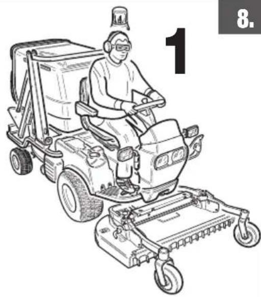
natural_image
Line drawing of a person operating a mobile cleaning or cleaning machine with wheels and a headlamp (no text or symbols)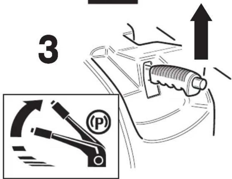
4
5
natural_image
Diagram of a car interior showing a car wheel and a screw, with an arrow pointing to the wheel (no text or symbols present)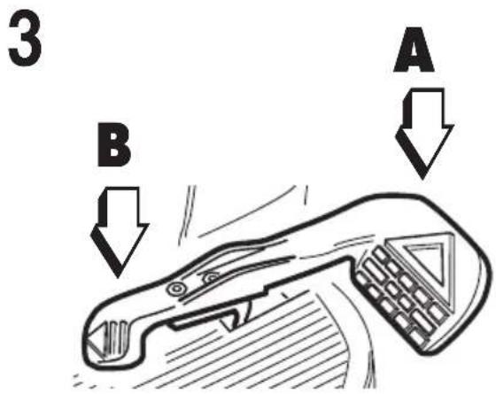
natural_image
Line drawing of a robotic vehicle with wheels and sensor, showing rotational motion arrows (no text or symbols)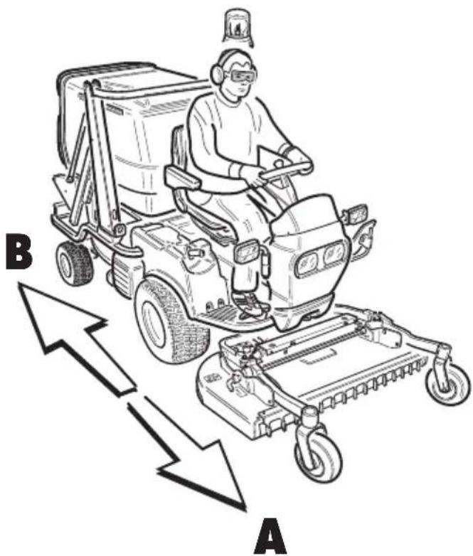
natural_image
Line drawing of a person operating a mobile cleaning or cleaning vehicle with directional arrows labeled A and B (no text or symbols on the diagram itself)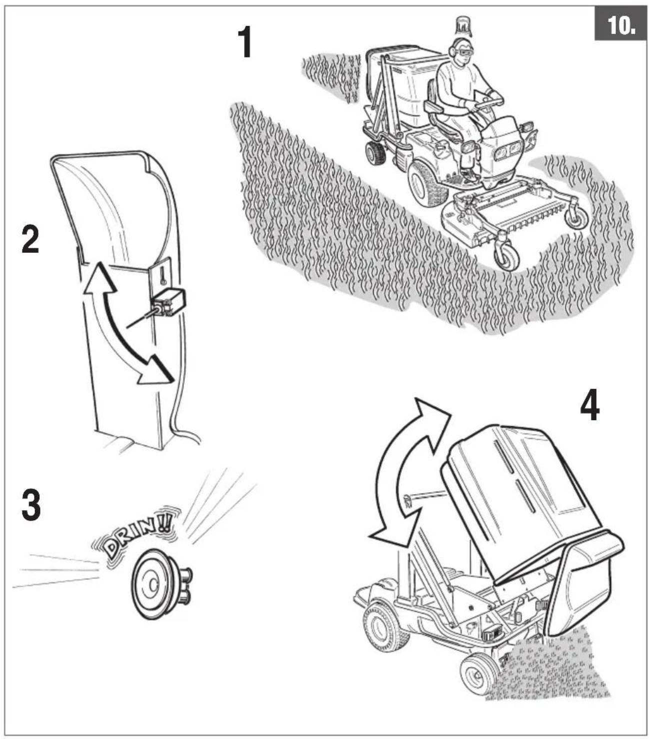
flowchart
graph TD
    A["DAIHATSU 950 D - 950 G"] --> B["OIL SHELL HELIX PLUS 10W40"]
    B --> C["KUBOTA D902"]
    C --> D["OIL SHELL HARVELLA T 15W-40"]
    D --> E["BRIGGS & STRATTON"]
    E --> F["OIL SHELL HELIX PLUS 10W-40"]
natural_image
Technical line drawings of a car interior and a mechanical device (no text or symbols)
13.8
natural_image
Technical line drawing of a mechanical assembly with a labeled component 'KUBOTA' (no other text or symbols)BRIGGS & STRATTON

A
natural_image
Diagram of a mechanical device with arrows indicating upward motion, no text or symbols present2
natural_image
Mechanical assembly diagram showing a valve and rotating component (no text or symbols)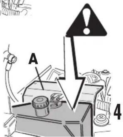
DAIHATSU 950D - 950G
natural_image
Technical diagram of a car battery pack with attached circuit lines and components (no text or labels)13.9
1
13.10
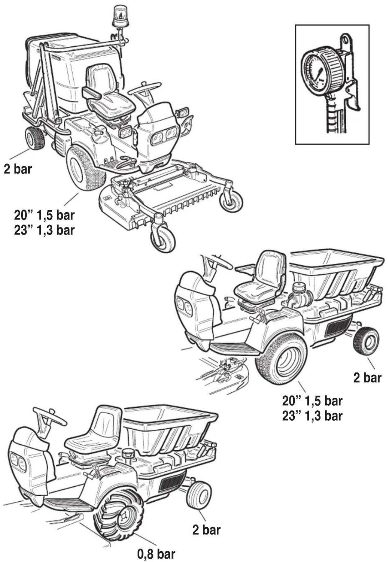
20" 1,5 bar
23" 1,3 bar
13.11
13.12
13.13

natural_image
Technical line drawing of a mechanical assembly with two labeled parts (no text or symbols present)
natural_image
Mechanical assembly diagram showing a tool inserted into a component, with no visible text or symbols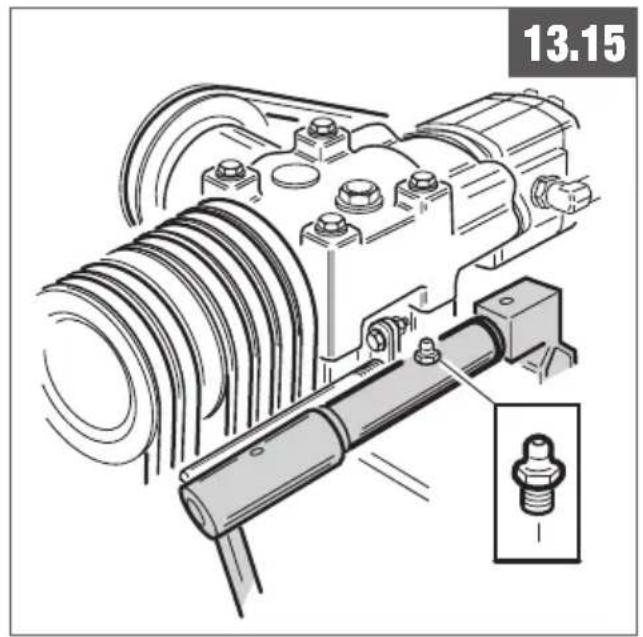
natural_image
Technical illustration of a mechanical assembly with a threaded component and a close-up inset showing a bolt detail (no text or symbols)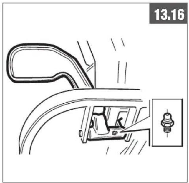
natural_image
Technical line drawing of a car door handle assembly with a screw inserted (no text or symbols)
natural_image
Line drawing of a car interior showing handshoe, seatbelt, and dashboard (no text or symbols)
1


8
9


10

natural_image
Three black-and-white pictograms showing a person moving a cart with an upward arrow, another pushing a basket, and a third pushing a truck (no text or symbols)12
NOTE
NOTE
www.gianniferrari.com
Advanced grounds care solutions
COMPANY
WITH QUALITY MANAGEMENT
SYSTEM CERTIFIED BY DNV
=ISO 9001:2000=

Gianni Ferrari

GIANNI FERRARI S.r.l.
Via Vespucci ,53 (z.ind. Ranaro)
Tel. +39.0522.973697 - Fax +39.0522.973707
e-mail: info@gianniferrari.com
OFFICINE BIEFFEBI S.p.A.
46023 Gonzaga (Mantova) Italy
Tel. +39.0376.52641 - Fax +39.0376.588270
e-mail: bieffebi@gianniferrari.com
Co. 00555600074
2010/00