Astroride A6.0FD - Electric bike Reebok - Free user manual and instructions
Find the device manual for free Astroride A6.0FD Reebok in PDF.
User questions about Astroride A6.0FD Reebok
0 question about this device. Answer the ones you know or ask your own.
Ask a new question about this device
Download the instructions for your Electric bike in PDF format for free! Find your manual Astroride A6.0FD - Reebok and take your electronic device back in hand. On this page are published all the documents necessary for the use of your device. Astroride A6.0FD by Reebok.
USER MANUAL Astroride A6.0FD Reebok
B Handlebar post set SET
B1 Handlebar pos 1 PCS
B-2 End cap 2 PCS
B-3 Handle pulse 2PCS
B-4 Screw 2 PCS
B-5 Bushing 2PCS
B-6 Handelbar axle
B-7 Flat washer 4PCS
B-B Semicircle washer
E-9 Console cable (uppe
B-IC Spring washer 8PCS
Boll-Swovs8PCS
10
B-13Hand pulse sensor wire 1PCS
5.14 Handedley 000
015
5.10 Waterborne bacteria 156
C1 Upper bandiebar set LSET
right)
C-R Upper handlebar set I SET
(Left)
C-1 Upperhandle bar (left) 1 PCS
C-2 Upperhandl bar (right) I PCS
C-3 End csg 2 PCS
C-1Foamgrn 2PC5
D Mainframe set 157
D1 Main frame 10C5
D-2 Dis per 2 ECS
Drs. Farwaber 1PCS
D4 Waveweasher 1PCS
D.5 Speed: LPG
D6 Speed sensor 1PCS
D7B 2PC
Dr-8 Drive boy 1PC5
P-9 Drive puly 1ECS
P12 Axie 1
P
D13: Ecorny5.BCB
P13Fide cover (p) 1PC
P14.2000 0.290
2017年1月14日
2016年1月1日
5%
D-17 98WTPCS
D-18 Disc inner cover 2PCS
D. 19 D86 2 PCS
D-20 Dsc plug 2PCS
D-21 Pattern nut 2PCS
D-22 Side cover (right) 1 PCS
P23PCWPE 1PC5
P21000
2
e
8391017
ITEM DESCRIPTION QTY.
E-1Scpy2PGS
E-2 Fatwaheh 2PCS
F1.Nu. 2PGG
510
E-3 Acquiescence of Moher PC5
E-Screw1PCS
E-7 Nut IPCS
E Handed 150
Ed Flnt waeer 4PCS
5.2Nk
1
F-2 Nut 8 PCS
F-5 Semicircle washer 4 PCS
F-6Carriage bolt 4PCS
F-7 Flgwsber 8PGS
E6 Hyesno head screw & FCS
5.8.10.2023年4月26日
7.10P2A
H0 2FC3
F-11 Hexagon hexa screw 2 PCS
F-12 Screw 4 PCS
F-13 Spring screw 4PCS
F-11Busing 4PCS
F-15 Cover of screw 2 PCS
F5-15 Fushing wench 1PC8
517
5.18 Xeohalpeal and 4PC
516Gawonbalt 1020
4
G Flywheel set 1 SET
G-HFlywheel 1PCS
G-2 Pattern nut 2PCS
G-3 N 3 PCS
0-4FleWsHER 1PCB
G-5Braun 1PC6
065
G-0 Hymnes 1
CPRSEATING 13E1
G-B Edhing 1PCS
H Front stabilizer set !SET
H1Frentstabilizer 1BCB
H2-ScreeX4PC9
H3 5ndcomp LPCB
110
A-4END CEP A
H-5 Transport Wheel 2PC5
H-6 Nut 2 PCS
H8EATX0
LeftpedalselSET
1
1
Lelpedal 1PCS
1-2 Rightpecls 1PC5
1-3Fedraltyer2ECS
Fushing 4PCS
1.000%
000000000000000000000000000000000000000
FATWASHER 6PC5
-7 Wave washer 2PCS
1-8 Pedal arm end cap 2 PCS
ITEM DESCRIPTION QTY.
8.701.240
127
A. Fader tube setting TSET
PegsIube(81)
J-2 Pedal tube (right) PC8
-53-lncnlo 2PCG
(4)When you are
15.000元4.000元
3.6Roller Cover 2PCS
J-7 Screw 4 PCS
H 4ECG
18
2-10 Suning 4PCs
J-1 Screw 4 PCS
+12Beller 2PCG
H3Screen 3 PC8
3-14 Hat Wainer 4PCS
J-15 Nut 2PC3
K-L Lowerhandebareset(1) SET
K3-10xhcbctbxtcty 1957
1
K1 - Low Power Amplifier (LP) - TPC
K-2Lowerhandbaright1PKs
K-3 ScRey 4 PC5
K4Bushyo 4EC8
1
E
L1RESSTGEBZERPCs
L-2 Screw4PCS
L3 Endcap L 1PCS
14.5%
1.24 100
E9 N1 4PC8
L8 Nut 4PCS
L-7 Adjaable pad 2PC9
L 3.PCS
105
E
M idler set
M1ScrewLPCS
M2N4LPC6
1
M-3 Flat Wigner TPCs
M-4 Spring 1PCS
M-5 Fixed brackets of spring 1 PCS
M5
10.5.2017年1月14日
M-5 SCHEW
M-9 ider wheel TPCS
No. Upper bandeher cover 3PCB
12.100%
1
(2)公司董事、监事和高级管理人员。
N-3 Pecar amnionover 2Pcs
N-4 Pedal am front cover 2 PC5
Integr 0
N-5 Cover of handlabeer post 1 FCS
N-6 Letpedal 1EC8
17
NO.1840026
N8 Cushionredfootpad 2FC5
N-9 Switching power 1PCS
adapter SV 2A
Reebok
Reebok
#
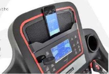
CONNECT YOUR SMARTPHONE TO YOUR NEW REEBOK EQUIPMENT
DOWNLOAD:
Search 'Recbok Fitness Equipment' on the App Store or Google Play.

Download on the
App Store

GETITON
Google Play
CONNECT:
Your Reboot machine connects to the app via the bluetooth dangle, so you don't need GPS or internet to use it.
The USB connector is colour coded blue to match the correct USB port on your machine.
Once you have selected a workout or planned your route, the app will ask you to choose the machine you would like to connect with.


PLAN YOUR ROUTE
Choose MAP MY ROUTE from the GET STARTED'ab.
- PRESET ROUTES:

There are 5 preset routines, that you can select from by clicking the preset icon.
D2.CUSTOMISEYOUR ROUTE:

First, Search for a location where you would like to plan your route.

Create your route by pressing on the map to choose your starting point, finish paint, and up to 8 way points.

START YOUR ROUTE

Once you have chosen your route, slide the 60 button left and then connect with your Roobok machine.
Once you have connected successfully, press start on your cardo equipment to begin your workout!
MONITOR WORKOUT DATA
To change the data view, swipe to scroll between workout data, elevation and HR/pace.

To remove the data view from the screen, press the data view button.


TRACK YOUR WORKOUT
The Reebak Fitness app allows you to track your progress via Google Maps.

You can switch the view between map, sale, flyover and street view.
The treadmill's elevation level will automatically adjust to match your programmed route, or if you are using a bike or cross trainer, the resistance level will automatically adjust accordingly.


ANALYSE YOUR TRAINING
At the end of your training session, the app shows you a workout profile, giving you stats such as distance covered, calories burned and average pace.
You can add personalised notes to your workout profile such as how challenging or hard you found the workout.
The training history page allows you to review your previous workouts and stats such as total number of calories burned.
More languages available at: reebokfitness.com/reebok-app

Reebok
ENGLISH


ENGLISH
Reebok
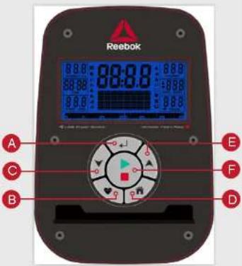
BUTTON FUNCTIONS

ENTER
Used to confirm a setting or selection

RECOVERY
To test heart rate recovery:

DOWN
To select training mode and adjust function
value down.

RESET
Used to reset the functions at any time. Please note STOP must be pressed before RESET.

To select training mode and adjust function value up.

START/STOP
To start or stop exercise.
OPERATION PROCEDURE
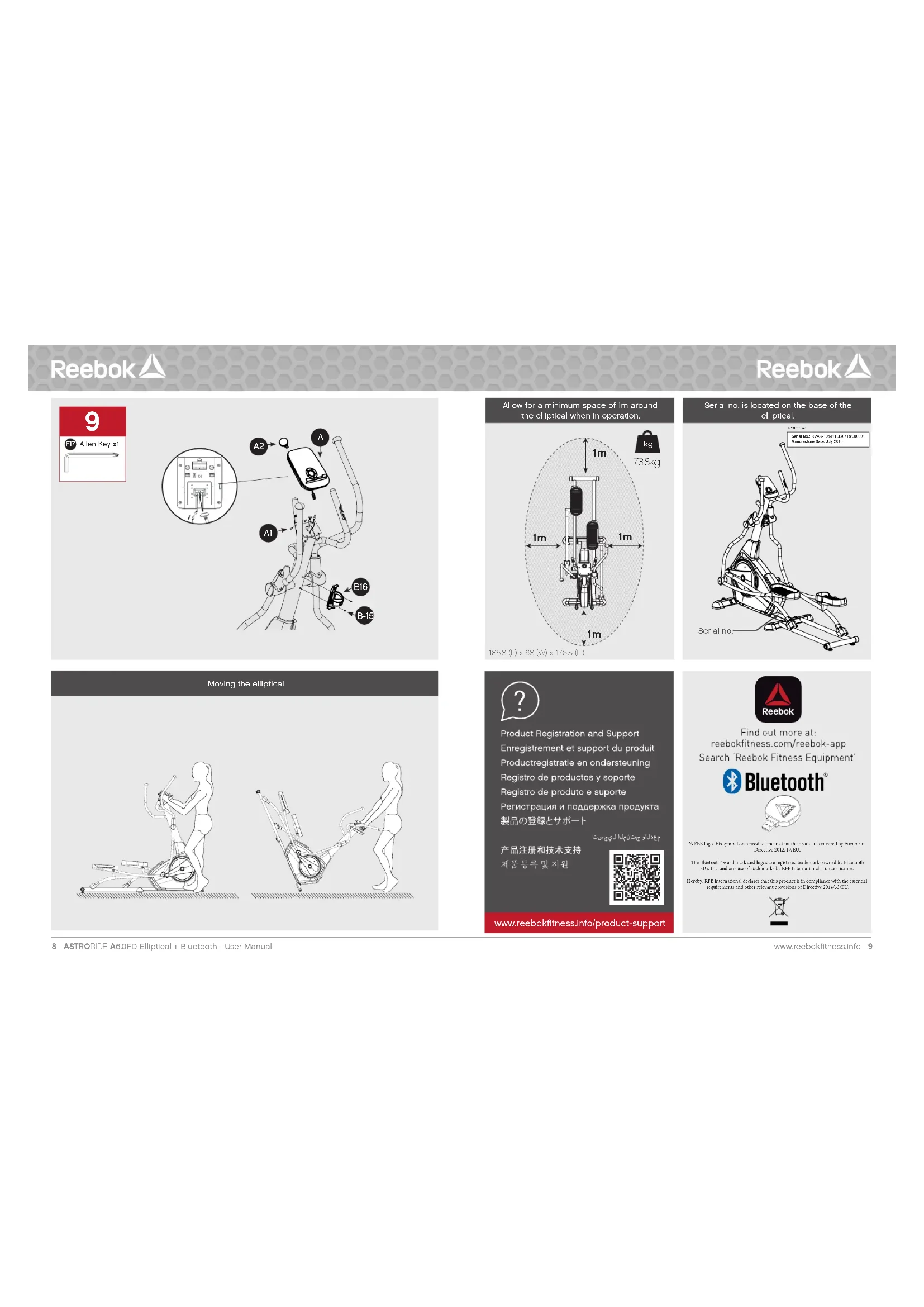
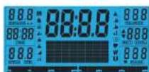
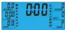
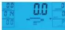
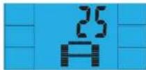
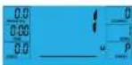
When the power supply is connected to the machine, the computer will power on with a long beep sound. All segments of the LCD display will light up for 2 seconds and the wheel diameter 78^ will be displayed as below.
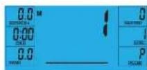
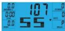
The main menu will be displayed. The user can press START to begin immediately in the manual mode. All Values (SPEED, DISTANCE, TIME) will count up from zero. Resistance level can be changed at any time during exercise by pressing UP or DOWN.
Before beginning the manual exercise the user can set the desired workout for TIME, DISTANCE, CALORIES and PULSE.
From main menu press UP/DOWN buttons to highlight MANUAL at the top of the screen. Press ENTER to
select M, then highlight value (Speed, Distance, Time, Pulse), use UP/DOWN to alter the data, and then press ENTER to confirm the setting. Press START to begin when details have been inputted. The inputted data will now count down from the entered information.

When setting the WATT level the resistance will automatically adjust to the preset WATTS regardless of the speed (except for very slow speed and higher WATTS settings where the resistance can only increase to 32).
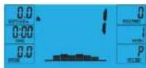
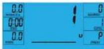
PROGRAM
- In main menu press UP/DOWN to highlight the program function.
- Press ENTER P1 will be displayed (After 2 seconds the program profile will be shown).
3.UseUP/DOWNtoselectprogramP1-P12. 4.PressEntertoenter the program. - Use UP/DOWN to change the program level.
- Press START to begin.
H.R.C (HEART RATE CONTROL)
- In main menu press UP/DOWN to highlight TARGET H.R.
- Press ENTER to select
- Age will be displayed, press UP/DOWN to change.
- Press ENTER to move to next section.
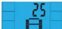
- The % of heart rate workout will be displayed. Press UP/DOWN between 55%, 75%, 90% and THR.

THR is the users preferred TARGET HEART RATE to work out to. This can be altered before the exercise is started.
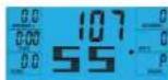
Maximum users heart rate is worked out at 220-age =total TARGET HEART RATE. This is the maximum your heart rate (MHR) should be. You can then work out at 55% 75% or 90% of this. For example 220-25(Users age)=195 MHR, from here you can work out at the desired %
- Press ENTER to confirm.
-
Computer will record the TARGET HEART RATE and allow the user to work out within this. The resistance level will automatically be changed.
-
If the heart rate is too high the computer will beep to indicate this.
-
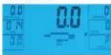
If no heart rate is being recorded the below will be displayed on the screen. In this instance ensure that both hands are securely holding the pulse sensors.
USER PROGRAM
User can create own profile.
- In main menu press UP/DOWN to select USER
- Program profile will be displayed as below.
- Press UP/DOWN to alter resistance level in the first
segment of the profile. - Press ENTER to move to the next segment.
- Continue the above for all columns.
- Press START to begin exercise once complete.
RECOVERY
At any time during workout RECOVERY button can be pressed to record recovery level.
Press RECOVERY button.
- Place both hands on the pulse sensors.
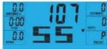
Computer will count down from 60 seconds and display the PULSE as below. DO NOT REMOVE YOUR HAND FROM PULSE SENSORS OR THE READING WILL NOT BE GIVEN.
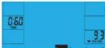
After the computer has counted down for 60 seconds a RECOVERY level reading will be given.

RECOVERY
F1Excellent
F2 Very Good
F3 Good
F4 Satisfactory
F5 Below Average
F6 Poor
NOTE
- This computer is powered by a 9V power adaptor. DO NOT USE ANY OTHER ADAPTOR WITH THE MACHINE.
- If the computer is inactive for approximately 4 minutes it will be turned off and the computer will restart. Press any button to turn the computer back on.
- If at any time the computer does not function correctly remove the power supply and reconnect it to restart.
Reebok
FRANCAIS


FRANCAIS
Reebok
FONCTION DES TOUCHES

ENTER

RECUPÉRATION
RESORT TARGET H.R. 1000
- PULSE ENTER para selectiona
3.3a mostrara la edad, pulse ARRIBA/ABAUO para modificarla.
RECOVERY (RESTITUTION)
For at tjekke restitution af hjertefrekyensen

DOWN (NED)
- I hovedmenuen tryk pa UP/DOWN for at markere
TARGET H.R. (Den valgte H.R.).
-
Tryk pa ENTER for at voelgo
-
Alder vises, tryk a UP/DOWN for at andre. 4. Tryk a ENTER for at gat til den neeste section.
- Procenctdien at hjertefrekvens-workoutenv issues. Tryk Pa UP/DOWN for at skite mellem 55%,75%,90% og THR.
THR (TARGET HEART RATE) er den HJERTEFREKVENS, som brugen foretreaskker til workouten. Den kan aandres,far traningan begynder.
Maksimum hyterefekvirens for brungeren regnes ud pa folgeende made: 220 minus akter = total TARGET HEART RATE (HJERTFEKVRENS). Det er den maksimalne hyterefekvirens (MHR). Du kan sa trane med 55% 75% aller 90% of donne. For eksekemp: 220 minus 25 (brugers akter) = 195 MHR (Maksimum hyterefekvirens). Herudjafer kan du sa trane med den ankske pracenteid.
- Tryk pA ENTER for at bekraefte
7.Computeren vill registre din MAKSIMALE
HJERTEFREKENS og du kan sa trae incen de\ donne.Modstandsvesue bilver mandret automatisk.8.Hvis hjertefrekuenser er for ho, vill computeren\ beepe for at andve ditte.
PAINIKKEIDEN TOIMINNOT

SYOTTO

PALAUTUMINEN
H.R.C. (SYKKEEN HALLINTA)
- Pina paëvalkössa YLOS -JALASPINIKKEITA
kostraeksai TAVOTESYKKFEN
2.Vaillse painamalla SYOTTOPAINIKETTA
PEKHM H.R.C. (KOHTPOAnb yACTOTbIyABCA)
1.B RABHOM MBHIO XONKBMUUPDOWN(BBEX/B-H3) 2.UBPOTPOWY TAPPOINT H.R.(BZF001475)
-
HAKIMITO KHONIKY ENTER.
-
Ha dinirme oToobpaxkaerch Boa pact
THeKHyUeOCC. YCTaHOBite npBaBmHObE 2AHAHEH KHOKTHAIUPDOWN (ABPey)
4. HIXMATE KHOHNY ENTER, YUO67 Nepetry K CnCNDYAMUY.

5.Ha dncnnee oTo6paXaaTc npadeneHbennnHa
mynbca [B npoeTHax TO MAKcHMaHo DOyCTMORO 2HHYAEK, NOCTXeHgK KOTOPD BYET
npodokkaTbCtpeHpoBa KhonKaMn (BeePxBn3)
BbepnE OHO H3aHcHm 55%,75%,90% H

THTRP#eAbeBbIyIpyL3aAabeH
H3MEHHTBNEPAHANOMTOEHDDAKI
Makchimambo apycttchmmynbcuHcHaeTcH Tc
cpmy220-0a3pact=6b5nTHHR He Cnueyt
ancyckbat,ntbmyncb Mybncbe 3to0 3haHHN
TpeHNPOKBA MOKET npOdoXkBaCBO TEO nop,
noka Nc TEPHYPOUeORG He yBENHHTCBO
55%,75% UIN 90%OT MAKCHIMHO DOYCTHMNO
Harmpem,ecn Bocapst TepHyPkyoERCC-25 net,
MAKCHIMHO DOYCTHMbl TYbBC COCTBnReT 220-
25=195.3a4hHbIe 3HaHHN HpyLc paaccnHbAotcH
bPOOHTQSTOT hnnnH
6.Haxmte KONX ENTER
7B Pnuece Tne Tnepnckn KmoTbTeP TeTnepKaesK KOHPOYET NpUC NoAe308eTN, CpBBHBeT EoC PnpeDnBHM NpBcOM KCOtBCTeBHNO HMeHHET HNp3YCK.
B. Ecm yactota nynbca nonbsObaTea
yEMHRCNMMKCMCMBPOaSaTCH 28VKO0BCH3A
9EcmnmepeHneynbcBHeo3mKHO.Ha mncnee
300PAAHCHCJGKAYMCHNCHNCH 1TEMCAVGHKKNKPOBMMTECKPVKKMA
3AATyKJ DYOBCA
CO3DAHME COBCTBEHHN IPOPTPAMMBI
PnIb03abTeB MoKTeCoaTaB coCbTeBHHyO nPcPmPyT TReHpOeKBHL
1.BFABHOMMeHIOKHONKAMNUP/DOWN(Bepx/
BHH3) b6epnre poxmM USER (nonaTeenb).
-
Hauchner 1967
-
KHOKAMU UP/DOWN (B6EPX/BH43) vCTAHOBITE
Harpysky nepboro cerMeHTa npoemna
- Haxmte KhoNky ENTER, 1robu nepenTn
HORTOHTYUKSSAHNEEETRNGB
COMSHTOBPOOHNH
- Noche yctaHOBK BCex NapaMeTpoB HAXMNTe
KHONKY START (ctapf), qTobbi Raqafb TpeHnpocSy.
BOCCTAHOB/HEHNE NY/ibCA
HaxMMTE KHOIky RECOVERY (BocTaHOBneHwe)
B ABOOM MOEMHT BO BPEM TpeHPOSKI,TOBOE EDOPDTHCACVVOOEOBROCTAHOOBHPOV
HaxMMTE KONKY RECOVERY (BOCCaHOBNEHne)
BocbMMTeCbObeHmPyKaMn3aDaTHKnYnbcA
YPOBHN BOCCTAHOBAEMHR
F1PpeBocxoAHO F2Ochb xopoAo
F3Xp0149DoutepinH
Fb Hnke cpeHrro Fblnoxo
PIMMEAHM
- Tybta npabnncn Bokn Knae Hcetbe Bokn
Nttnnnn Hn nnnnnn 9B. NcNb30b4b5 APTYHE
BOKNI NNTAHIR C PTHAEKEXPOH ME DDTGYCAETR. - C-37CnAePocTn TpO-AkBeKn B TcNnBcKo 4 MNHTI
Nttnnnn Hn nnnnnnn 9B. NcNb30b4b5 Cogdakn
Hardyavc, Atehnetnehckn BaKApKanov, UtoBcKoKnih
nyt, Hnntnne TnnoNy KcnKo
+Eon nVbT pabctn HappanBn. onnHrte Ene
Reebok
中文


中文
For product information or service please contact:
UK: RFE Europa Ltd. 8 Clarendon Drive, Wymbush, Milton Keynes, MK8 8ED.
Customer Service: Tel: +44 (0)800 440 2459 Email: techsupport@rfeinternational.com
Europe: serviceeuropa@rfeinternational.com
Spain: serviciotecnico@rfeinternational.com
APAC (excluding Australia): RFE Asia Pacific, 2608-1609, 1 Hung To Road, Kwun Tong, Kowloon, Hong Kong.
Customer Service: Tel: +852 34685027 Email: techsupportapac@rfeinternational.com
Australia: techsupportaustralia@rfeinternational.com
USA: RFE Sporting Goods Inc., 1300 Smith Road, STE 104, Austin, Texas, 78721, USA.
Email: techsupportusa@rfeinternational.com