
GZC 64300 - Cooker TEKA - Free user manual and instructions
Find the device manual for free GZC 64300 TEKA in PDF.
| Product type | Built-in gas hob |
| Brand | Teka |
| Model | GZC 64300 |
| Number of burners | 5 |
| Ultra-rapid burner (DCC AFB) | 4000 W |
| Rapid burner | 2800 W |
| Reduced semi-rapid burner | 1400 W |
| Semi-rapid burner | 1750 W |
| Auxiliary burner | 1000 W |
| Gas supply | Natural gas G20 (20 mbar), butane G30 (28-30 mbar), propane G31 (37 mbar) |
| Electrical supply | 220-240 V ~ 50-60 Hz |
| Appliance dimensions (W x D) | 570 x 480 mm |
| Built-in dimensions (W x D) | 570 x 480 mm |
| Appliance height | 60 mm |
| Energy efficiency (EEgashob) | 57.0 % |
| Cooking surface | Ceramic glass |
| Ignition type | Integrated automatic electric |
| Safety device | Safety thermocouple on each burner |
| Grid material | Enamel |
| Cleaning | Glass surface washable with soapy water, removable burners and grids |
| Spare parts available | Nozzles, gaskets, spark plugs, thermocouples, taps |
| Warranty | 2 years (manufacturer standard) |
Frequently Asked Questions - GZC 64300 TEKA
- Ultra-rapid: 24-26 cm
- Rapid: 20-22 cm
- Reduced semi-rapid and semi-rapid: 16-18 cm
- Auxiliary: 10-14 cm.
Do not exceed maximum dimensions to avoid overheating.
User questions about GZC 64300 TEKA
0 question about this device. Answer the ones you know or ask your own.
Ask a new question about this device
Download the instructions for your Cooker in PDF format for free! Find your manual GZC 64300 - TEKA and take your electronic device back in hand. On this page are published all the documents necessary for the use of your device. GZC 64300 by TEKA.
USER MANUAL GZC 64300 TEKA
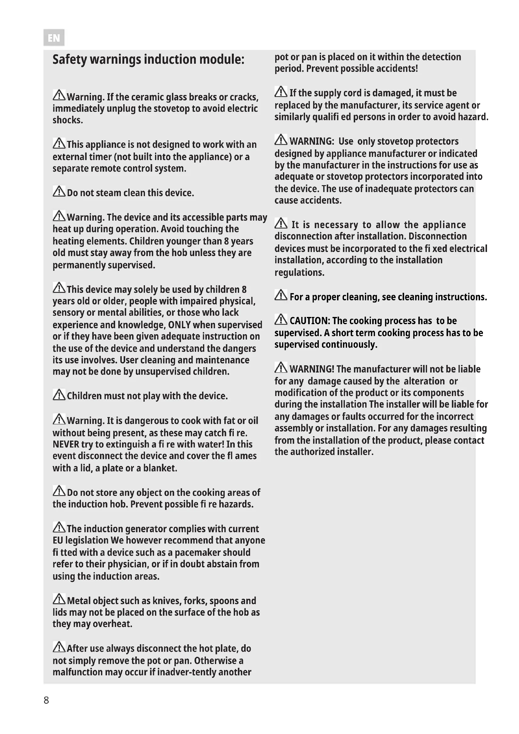
(^*) air inlet: see installation chapter (paragraphs 5 and 6)
345
6 6/A 6/B
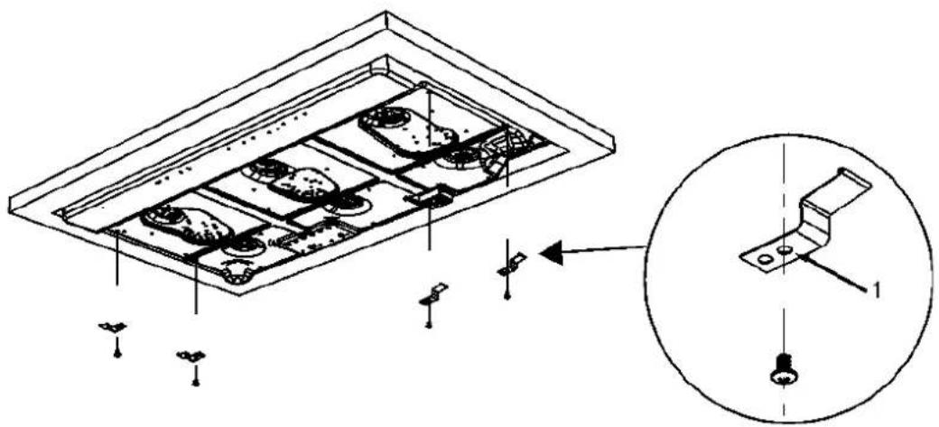
WARNING! In the need to disassemble the hob, first remove the screw on the bottom, as shown in the fi gure to side!
Procedure for a correct installation of the hob
INSTALLATION TYPE: A
Lateral chrome / Chrome létral
MODEL:
GZC 63310
GZC 64300
GZC 64320
GZC 64321
GZC 75330
GZC 85320
9
MODEL:
GZC 95320
GZC 96310
9/A 9/B
INSTALLATION TYPE: A
Warning. If the ceramic glass breaks or cracks, immediately unplug the stovetop to avoid electric shocks.
This appliance is not designed to work with an external timer (not built into the appliance) or a separate remote control system.
Do not steam clean this device.
Warning. The device and its accessible parts may heat up during operation. Avoid touching the heating elements. Children younger than 8 years old must stay away from the hob unless they are permanently supervised.
This device may solely be used by children 8 years old or older, people with impaired physical, sensory or mental abilities, or those who lack experience and knowledge, ONLY when supervised or if they have been given adequate instruction on the use of the device and understand the dangers its use involves. User cleaning and maintenance may not be done by unsupervised children.
Children must not play with the device.
Warning. It is dangerous to cook with fat or oil without being present, as these may catch fire. NEVER try to extinguish a fire with water! In this event disconnect the device and cover the fl ames with a lid, a plate or a blanket.
Do not store any object on the cooking areas of the induction hob. Prevent possible fire hazards.
The induction generator complies with current EU legislation We however recommend that anyone fitted with a device such as a pacemaker should refer to their physician, or if in doubt abstain from using the induction areas.
Metal object such as knives, forks, spoons and lids may not be placed on the surface of the hob as they may overheat.
After use always disconnect the hot plate, do not simply remove the pot or pan. Otherwise a malfunction may occur if inadvertently another
pot or pan is placed on it within the detection period. Prevent possible accidents!
If the supply cord is damaged, it must be replaced by the manufacturer, its service agent or similarly qualifi ed persons in order to avoid hazard.
WARNING: Use only stovetop protectors designed by appliance manufacturer or indicated by the manufacturer in the instructions for use as adequate or stovetop protectors incorporated into the device. The use of inadequate protectors can cause accidents.
It is necessary to allow the appliance disconnection after installation. Disconnection devices must be incorporated to the fixed electrical installation, according to the installation regulations.
For a proper cleaning, see cleaning instructions.
CAUTION: The cooking process has to be supervised. A short term cooking process has to be supervised continuously.
WARNING! The manufacturer will not be liable for any damage caused by the alteration or modification of the product or its components during the installation The installer will be liable for any damages or faults occurred for the incorrect assembly or installation. For any damages resulting from the installation of the product, please contact the authorized installer.
GZC 31330
GZC 32300 GZC 63310
GZC 64300
GZC 64320
GZC85320 GZC75330
GZC 96310 GZC 95320
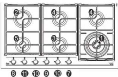
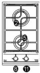
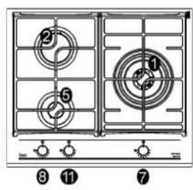
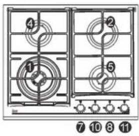
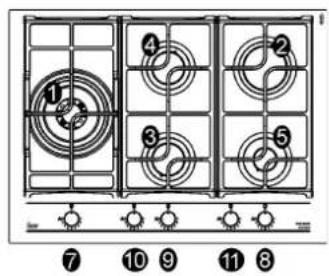
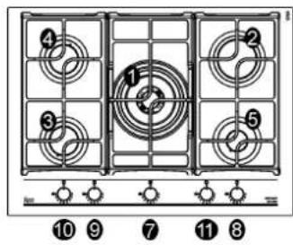
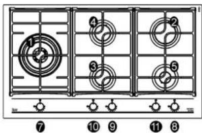
| 1 Ultra rapid gas burner (*DCC AFB) of 4000 W | |
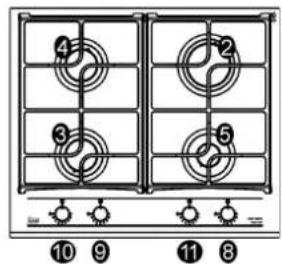
| 2 Rapid gas burner of 2800 W | |
| 3 Semirapid gas burner reduced of 1400 W | |
| 4 Semirapid gas burner of 1750 W | |
| 5 Auxiliary gas burner of 1000 W | |
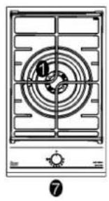
| 7 Burner n° 1 control kno | |
| 8 Burner n° 2 control knob | |
| 9 Burner n°3 control knob | |
| 10 Burner n° 4 control knob | |
| 11 Burner n° 5 control knob | |
| *DCC AFB: Air From The Bottom (fi g. 13/B). | |
| Attention: this appliance has been manufactured for domestic use only and it employment by private person | |
This cook top was designed to be used exclusively as a cooking appliance: any other use (such as heating room) is to be considered improper and dangerous.
1) BURNERS
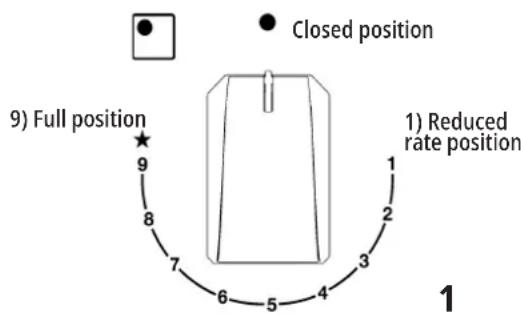
A diagram is screen-printed above each knob on the front panel. This diagram indicates to which burner the knob in question corresponds. After having opened the gas mains or gas bottle tap, light the burners as described below:
- use adequate pans for each burner (consult the following table and fig. 2).
- When the pan comes to the boil, set the knob to the reduced rate position (Position 1, fig. 1).
- Always place a lid on the pans.
-Use only pan with a fl at bottom.
- automatic electrical ignition
Push and turn the knob corresponding to the required burner
in an anticlockwise direction until it reaches the full on position. These indications help to save energy and prevent damage to of full (position 9 fi g. 1), then depress the knob, the tap is food pans. Use only containers of suitable diameters. The pan equipped with a scale of 9 positions, with each click the fl am must not exceed the edges of the hob. Do not use small pans is reduced until you reach the position of 1, ie the minimum on large burners. The fl am should not touch the sides of supply of gas. the container.
APPROPRIATE PAN AND CONTEINERS
- Lighting burners equipped with fl ame failure device
The knobs of burners equipped with flame failure device must be turned in an anticlockwise direction until they reach the full on position (Position 9, fi g.1) and come to a stop. Now depress the knob in question and repeat the previously indicated operations.
Keep the knob depressed for about 10 seconds once the burner has ignited.
Then follow the instructions for using the tap as explained above.
With regards to all the models, in case of accidental extinguishment of the flame, disengage the ignition by rotating the knob to the off position. Wait at least 1 minute before re-igniting the flame.
81216133
Only use pans with a concave base on the multi-crown burners. If the pan dimension is larger than 26cm always use the extra pan support shown in the figure below (cod. 81216133).
The accessories can be bought through the After Sales Service net.
HOW TO USE THE BURNERS
Bear in mind the following indications in order to achieve maximum efficiency with the least possible gas consumption
WARNING:
-burners with flame failure device may only be ignited when the relative knob has been set to the Full on position (Position 9, fig. 1).
-Matches can be used to ignite the burners in a blackout. Never leave the appliance unattended when the burners are being used. Make sure there are no children in the near vicinity. Particularly make sure that the pan handles are correctly positioned and keep a check on foods requiring oil and grease to cook since these products can easily catch fire.
-
Never use aerosols near the appliance when it is operating.
-
Containers wider than the unit are not recommended.
- If the installation requires modifi cations to the home's electrical system or if the socket is incompatible with the appliance's plug, have changes or replacements performed by professionally-qualified person. In particular, this person must also make sure that the section of the wires of the socket is suitable for the power absorbed by the appliance.
- Use of a gas cooking appliance produces heat and
| Burners | Pan Ø in cm (min) | Pan Ø in cm (max) |
| Ultrarapid 24 26 | ||
| Rapido 20 22 | ||
| Reduced semi-rapid | 16 18 | |
| Semirapid | 16 18 | |
| Auxiliary | 10 14 |
moisture in the room in which it is installed. The room must therefore be well ventilated by keeping the natural air vents clear (see fi g. 2) and by activating the mechanical aeration device (suction hood or electric fan fi g. 3 and fi g. 4).
- Intensive and lengthy use of the appliance may require additional ventilation. This can be achieved by opening a window or by increasing the power of the mechanical exhausting system if installed.
- Do not attempt to change the technical characteristics of the product because it can be dangerous.
-
If you should not to use this appliance any more (or replace an old model), before disposing of it, make it inoperative in conformity with current law on the protection of health and the prevention of environmental pollution by making its dangerous parts harmless, especially for children who might play on an abandoned appliance.
-
CAUTION:
-
Do not touch the appliance with wet or damp hands or feet. Do not use the appliance barefoot
- The manufacturer will not be liable for any damage resulting from improper, incorrect or unreasonable use.
- During, and immediately after operation, some parts of the cook top are very hot: avoid touching them.
- After using the cook top, make sure that the knob is in the closed position and close the main tap of the gas supply or gas cylinder.
- If the gas taps are not operating correctly, call the Servi Department.
-IMPORTANT!
A perfect installation, adjustment or transformation of the cook top to use other gases requires a QUALIFIED INSTALLER: a failure to follow this rule will void the warranty.
IMPORTANT:
always disconnect the appliance from the gas and electricity mains before carrying out any cleaning operation.
2) GAS HOB
It is very important to clean the surface soon after every use, when the glass is still tepid.
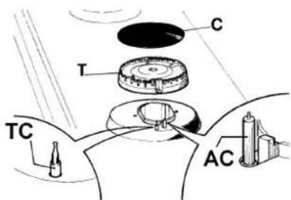
Periodically wash the gas hob, the enameled steel pan support, the enameled burner caps "A", "B" and "C" and the 3 burner heads "T" (see fig. 6 - 6/A) with lukewarm soapy water.
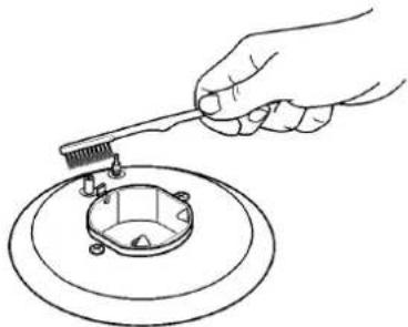
They should also be cleaned plugs "AC" and fl ame detection "TC" (see fi g. 6). Clean them gently with a small nylon brush as shown (see fi g. 6/B) and allow to dry fully.
Do not wash in the dishwasher.
Do not allow vinegar, coffe, milk, salted water, lemon or tomato juice from remaining in contact with the enameled surfaces for long periods of time.
Do not use metallic sponges, powder abrasives or corrosive sprays.
WARNING:
comply with the following instructions, before remounting the parts:
-check that burner heads slots (see fig. 6 - 6/A) have not become clogged by foreign bodies.
-Check that enameled burner cap "A-B-C" (fig. 6-6/A) have correctly positioned on the burner head. It must be steady.
- The pan support must be placed in the appropriate centering pins (Or on the aluminium profile if present). Verifying the perfect stability.
-Do not force the taps if they are difficult open or close. Contact the technical assistance service for repairs.
- Don't use steam jets for the equipment cleaning.
CAUTION:
In case of hotplate glass breakage:
- shut immediately off all burners and any electrical heating element and isolate the appliance from the power supply;
- do not touch the appliance surface;
- do not use the appliance.
Note: continuous use could cause the burners to change colour due to the high temperature.
TECHNICAL INFORMATION FOR THE INSTALLER
Installation, adjustments of controls and maintenance must only be carried out by a qualified engineer. The appliance must be correctly installed in conformity with current law and the manufacturer's instructions. Incorrect installation may cause damage to persons, animals or property for which the Manufacturer shall not be considered responsible.
During the life of the system, the automatic safety or regulating devices on the appliance may only be modified by the manufacturer or by his duly authorized dealer.
3) INSTALLING THE GAS HOB
Check that the appliance is in a good condition after having removed the outer packaging and internal wrappings from around the various loose parts. In case of doubt, do not use
EN
the appliance and contact qualifi ed personnel.
Never leave the packaging materials (cardboard, bags, polystyrene foam, nails, etc.) within children's reach since they could become potential sources of danger.
The measurements of the opening made in the top of the modular cabinet and into which the gas hob will be
installed are indicated in either fig. 7. Always comply with the of the crystal. The ends of the strips must fit together without measurements given for the hole into which the appliance wilbwrapping.
be recessed (see fig. 7 and).
The appliance belongs to class 3 and is therefore subject to all the provisions established by the provisions governing such appliances.
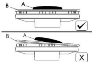
Caution: Do not allow the glass (A) lay directly on the wo top. it is the metal bottom "carter" (B) that has to be in touch with the work top (see fig. 11/A).
4) FIXING THE GAS HOB
INSTALLATION TYPE: A
The gas hob has a special seal which prevents liquid from infi ltrating into the cabinet. Strictly comply with the following instructions in order to correctly apply this seal:
-
take off all the movable parts of the hob.
-
Cut the seal in 4 parts of the necessary lenght to positioning it on the 4 edges of the crystal.
-Overturn the gas hob and correctly position seal "E" (fi g. 11/B) under the edge of the gas hob itself, so that the outer side of the seal perfectly matches the outer perimetal edge of the crystal. The ends of the strips must fi t together without overlapping.
-Evenly and securely fix the seal to the crystal, pressing it in place with the fingers.
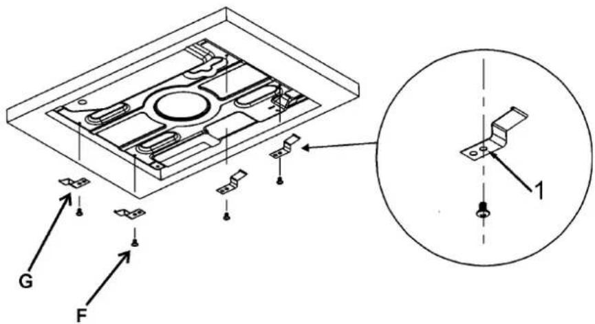
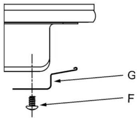
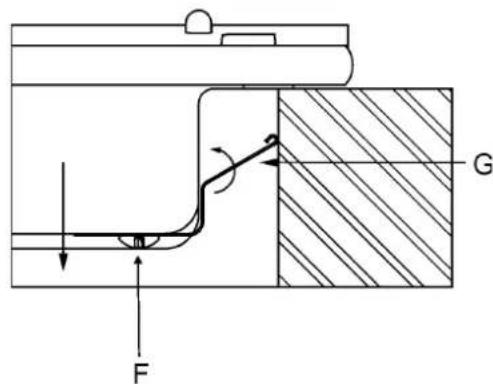
-Place the hooks in their respective positions, use the hole no 1 as reference for position lateral (fi g. 9) and hole no. 2 for positions rear (fi g. 10).
-Secure hooks "G" by means of screws "F" (fi g. 9/A for lateral and fi g. 10/A for rear).
-Insert the cooking hob in the hole of the kitchen cabinet by exercising a certain level of force in order to get over the resistance of the hooks (fi g. 9/B for lateral and fi g. 10/B for rear).
- In order to avoid accidental touch with the overheating bottom of the hob, during the working, is necessary to put a wooden insert, fixed by screws, at a minimum distance of 70 mm from the top (see fi g. 7).
INSTALLATION TYPE: B
The gas hob has a special seal which prevents liquid from infi ltrating into the cabinet. Strictly comply with the following instructions in order to correctly apply this seal:
- take off all the movable parts of the hob.
- Cut the seal in 4 parts of the necessary lenght to positioning at on the 4 edges of the crystal.
-Overturn the gas hob and correctly position seal "E" (fi g. 11/B under the edge of the gas hob itself, so that the outer side of the seal perfectly matches the outer perimetral edge of the crystal. The ends of the strips must fit together without overlapping.
-Evenly and securely fix the seal to the crystal, pressing it in place with the fingers. - Position the hob in the hole in the unit and fasten it in place using the appropriate screws "F" of the fastening hooks "G" (see fig. 11).
k In order to avoid accidental touch with the overheating bottom of the hob, during the working, is necessary to put a wooden insert, fixed by screws, at a minimum distance of 70 mm from the top (see fi g. 7).
5) ROOM VENTILATION
It is essential to ensure that the room in which the appliance is installed is permanently ventilated in order to allow the appliance itself to operate correctly. The necessary amount of air is that required for regular gas combustion and ventilation of the relative room, the volume of which must not be less than 20m^3 . Air must naturally flow through permanent openings in the walls of the room in question. These openings must vent the fumes outdoors and their section must be at least 100cm^2 (see fig. 3). Construction of the openings must ensure that the openings themselves may never be blocked. Indirect ventilation by air drawn from an adjacent room is also permitted, in strict compliance with the provisions in force.
CAUTION: if the burners of the cooking top are without safety thermocouple, the ventilation outlet must have a minimum 200~cm^2 section.
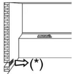
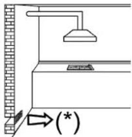
6) LOCATION AND AERATION
Gas cooking appliances must always dispose of their combustion fumes through hoods. These must be connected to flues, chimneys or straight outside. If it is not possible to install a hood, an electric fan can be installed on a window or on a wall facing outside (see fi g. 4). This must be activated at the same time as the appliance (see fi g. 5), so long as the specific cations in the provisions in force are strictly complied with.
7) GAS CONNECTION
Before connecting the appliance, check that the values on the data label affixed to the underside of the gas hob correspond to those of the gas and electricity mains in the home.
A label on the appliance indicates the regulating conditions: type of gas and working pressure. Gas connection must comply with the pertinent standards and provisions in force.
When gas is supplied through ducts, the appliance must be connected to the gas supply system:
- with a rigid steel pipe. The joints of this pipe must consist of threaded fittings conforming to the standards.
- With copper pipe. The joints of this pipe must consist of unions with mechanical seals.
- With seamless fl exible stainless steel pipe. The length of this pipe must be 2 meters at most and the seals must comply with the standards.
When the gas is supplied by a bottle, the appliance must be fuelled by a pressure governor conforming to the provisions in force and must be connected:
- with a copper pipe. The joints of this pipe must consist of unions with mechanical seals.
- With seamless fl exible stainless steel pipe. The length of this pipe must be 2 meters at most and the seals must comply with the standards. It is advisable to apply the special adapter to the fl exible pipe. This is easily available from the shops and facilitates connection with the hose nipple of the pressure governor on the bottle.
- With rubber hose pipe in compliance with standards. The diameter of this hose pipe must be 8mm and its length must be no less than 400mm and no more than 1500mm . It must be firmly fixed to the hose nipple by means of the safety clamp specified by standards.
WARNING:
remember that the gas inlet union on the appliance is a 1/2'' gas parallel male type in compliance with ISO 228-1 standards.
Installation of stainless steel pipe and rubber hose pipe must ensure that it is never able to touch mobile parts of the built-in cabinet (eg. drawers). Furthermore, it must not pass through compartments that could be used for storage purposes.
When using a rubber hose pipe, it is essential to comply with the following instructions:
-no part of the pipe must be able to touch parts the temperature of which exceeds 90^
- The pipe must not be pulled or twisted, throttled or tightly bent.
-It must not come into contact with sharp edges or corners.
- It must be easy to inspect the entire pipe length in order to check its state of wear.
- The pipe must be replaced within the date stamped on
the pipe itself.
CAUTION:
If the appliance is placed on a base, measures have to be taken to prevent the appliance slipping from the base. The applianche must not be installed behind a decorative door in order to avoid overting.
The electrical connections of the appliance must be carried out in compliance with the provisions and standards in force. Before connecting the appliance, check that:
-
the voltage matches the value shown on the specific cation plate and the section of the wires of the electrical system can support the load, which is also indicated on the specific cation plate.
-
The electrical capacity of the mains supply and current sockets suit the maximum power rating of the appliance (consult the data label applied to the underside of the gas hob).
-
The socket or system has an efficient earth connection in compliance with the provisions and standards in force. The manufacturer declines all responsibility for failing to comply with these provisions.
When the appliance is connected to the electricity main by a socket:
- fit a standard plug "C" suited to the load indicated on the data label to the cable. Fit the wires following figure 8, taking care respecting the following correspondences:
Letter L (live) = brown wire;
Letter N (neutral) = blue wire;
earth symbol 12 = green - yellow wire.
- The power supply cable must be positioned so that no part of it is able to reach an temperature of 90^ .
- Never use reductions, adapters of shunts for connection since these could create false contacts and lead to dangerous overheating.
- The outlet must be accessible after the built-in.
When the appliance is connected straight to the electricity main:
-install an omnipolar circuit-breaker between the appliance and the electricity main. This circuit-breaker should be sized, in compliance with current installation regulations.
-Remember that the earth wire must not be interrupted by the circuit-breaker.
r-For optimum safety, the electrical connection may also be protected by a high sensitivity diff erential circuit- breaker. You are strongly advised to fi x the relative yellow-green earth
EN
wire to an efficient earthing system.
Before performing any service on the electrical part of the appliance, it must absolutely be disconnected from the electrical network.
Always disconnect the appliance from the electricity main before making any adjustments.
All seals must be replaced by the technician at the end of any adjustments or regulations.
Our burners do not require primary air adjustment.
9) TAPS
"Reduced rate" adjustment
-Switch on the burner and turn the relative knob to the "Reduced rate" position (small flame fig. 1).
- Remove knob "M" (fi g. 12 and 12/A) of the tap, which is simply pressed on to its rod. The by-pass for minimal rate regulation can be: beside the tap (fi g. 12) or inside the shaft. In any case, to access to regulation, it can be done through the insertion of a small screwdriver "D" beside the tap (fi g. 12 or in the hole "C" inside the shaft of the tap
(fig 12/A). Turn the throttle screw to the right or left until the burner flame has been adequately regulated to the "Reduced rate" position.
The flame should not be too low: the lowest small flame should be continuous and steady. Re-assemble the several components.
It is understood that only burners operating with G20 gas should be subjected to the above mentioned adjustments. The screw must be fully locked when the burners operate with G30 or G31 (turn clockwise)
10) REPLACING THE INJECTORS
The burners can be adapted to different types of gas by mounting injectors suited to the type of gas in question. To do this, fi rst remove the burner tops using a an appropriate tool. Now unscrew injector (see fi g. 13 - 13/A - 13/B) and fi t a injector corresponding to the utilized type of gas in its place.
To access the injector, in ultra-fast burners with DCC AFB, remove the injector cover "A" (fig. 13/B).
It is advisable to strongly tighten the injector in place. After the injectors have been replaced, the burners must be regulated as explained in paragraphs 9. The technician must reset any seals on the regulating or pre-regulating devices. The envelope with the injectors and the labels can be included in the kit, or at disposal to the authorized customer Service Centre.
For the sake of convenience, the nominal rate table also lists the heat inputs of the burners, the diameter of the injectors and the working pressures of the various types of gas.
2TAPS LUBRIFICATION
Should a tap being blocked, do not force and ask for Technical Assistance.
| BURNERS | GAS | NORMAL PRESSURE | NORMAL RATE | INJECTOR DIAMETER | NOMINAL HEAT INPUT (W) | ||||
| N° | DESCRIPTION mbar g | /h l/h 1/100 mm Min. Max. Eegasburner** | |||||||
| 1 | ULTRA RAPID DCC AFB* | G30 - BUTANE | 28 - 30 | 291 | 100 H1 | 1800 | 4000 | 55,9% | |
| G31 - PROpane | 37 | 286 | 100 H1 | 1800 | 4000 | ||||
| G20 - NATURAL | 20 | 381 | 150 Z1 | 1800 | 4000 | ||||
| 2 | RAPID | G30 - BUTANE | 28 - 30 | 204 | 83 | 900 | 2800 | 58,0% | |
| G31 - PROpane | 37 | 200 | 83 | 900 | 2800 | ||||
| G20 - NATURAL | 20 | 267 | 117 S | 900 | 2800 | ||||
| 3 | SEMIRAPID REDUCED | G30 - BUTANE | 28 - 30 | 102 | 60 | 550 | 1400 | 60,0% | |
| G31 - PROpane | 37 | 100 | 60 | 550 | 1400 | ||||
| G20 - NATURAL | 20 | 133 | 88 Z | 550 | 1400 | ||||
| 4 | SEMIRAPID | G30 - BUTANE | 28 - 30 | 127 | 65 | 550 | 1750 | 63,0% | |
| G31 - PROpane | 37 | 125 | 65 | 550 | 1750 | ||||
| G20 - NATURAL | 20 | 167 | 97 Z | 550 | 1750 | ||||
| 5 | AUXILIARY | G30 - BUTANE | 28 - 30 | 73 | 50 | 450 | 1000 | N.A. | |
| G31 - PROpane | 37 | 71 | 50 | 450 | 1000 | ||||
| G20 - NATURAL | 20 | 95 | 72 X | 450 | 1000 | ||||
**In accordance with Regulation No. 66/2014 EU measures for the implementation of Directive 2009/125/EC, the performance (EEgas burner) was calculated according to EN 30-2-1 last review with the G20.
*DCC AFB: Aire de la parte inferior (fig. 13/B).
TYPE AND SECTION OF THE POWER CABLES
| TYPE DE CABLE | MONOPHASE POWER SUPPLY | ||
| Gas | B | H05 RR-F | 3 x 0.75 mm² |
| H05 RN-F | |||
| H07 RN-F | |||
ATTENTION!!!
If the power supply cable is replaced, the installer should leave the ground wire (B) longer than the phase conductors (fig. 14) and comply with the recommendations given in paragraph 8.
WARNING: MAINTENANCE MUST ONLY BE
PERFORMED BY AUTHORISED PERSONS.
In case of failure or cut in the cable, please move away from the cable and do not touch it. Moreover the device must be unplugged and not switched on. Call the nearest authorized service center to fix the problem.
TROUBLESHOOTING TABLE
| PROBLEMS CAUSES SOLUTIONS | ||
| The gas ring burns unevenly | Burner crown maybe occluded by dirty Wrong gas regulation | Clean the burner crown with metal cleaning agent Call the assistance |
| Burner fl ame suddenly changes Incorrect burner components assembly Assembly | Incorrect burner components assembly Assembly | the burner components correctly |
| Ignition of burners takes excessively long | Incorrect burner components assembly Assembly | imbly the burner components correctly |
| The fl ame goes off after ignition | Early release of knob. Knob is not pushed in fi rmly Uncorrect pan dimension Thermocouple problems | Keep the knob pressed longer. Before releasing the knob, give it one fi nal solid push If the fl ame goes out with a pan larger than those indicated in the booklet, the user must use the appropriate "paillero" grid Move the thermocouple Call the assistance |
| The colour of the pan support has changed | Normal situation, caused by the high temperature | Clean the pan support with metal cleaning agents |
| The burner fails to ignite after pressing the knob (the spark-plug emit the spark) | Lack of gas or dirty on spark-plug | Clean the spark-plug like described in the cleaning chapter on instruction manual |
| The burner fails to ignite after pressing the knob (the spark-plug do not emit the spark) | Spark-plug or ignition generator problems | Call the assistance |
| The ignition generator does not work | Lack of electricity Incorrect ignition generator assembly or break | Check that the plug is inserted. Verify that the counter is turned on. Call the assistance |
| The spark-plug emit continuously the spark | Humidity Incorrect micro-switch assembly or break | Remove the power for 24 hours and allow the top to dry; verify that all the bushings are mounted correctly Call the assistance |
INSTALLATION TYPE: A
lettler L (phase) = fi l marron;
lettre N (neutre) = fi bleu;
10) REMPLACEMENT DES BUSES
ROBINETS LUBRIFICATION
**DCC AFB: 113 (J) J (J) (J) (J)
aBb
| \( {}^{1} \)  |  | |||
| \( {}^{2} \sim {0.75} \times 3 \) | H05 RR-F H05 RN-F H07 RN-F | B |  |
8.
baiy
.
y
alakcll 1y aiaa 4s jy yjai. alaii y jg j
AR
Jaaal Jaaa a jy bce .0e i oosai Iaiaai 1i aie aie G31 g G30 e Jaaiaia
J (10
J 13/A-13
AilS a 1000000000000000000000000000000000000000000000000000000000000000000000
J 10000000000000000000000000000000000000000000000000000000000000000000000000
i 1
illl llll llll 111
()
J 8 8
$$ ; \text {i} _ {\text {i}} \text {i} _ {\text {i}} = (\varphi) L \omega_ {\text {i}} $$
$$ ; \text {g r i g h t} = (\lambda) \quad N \quad \text {的} $$
$$ j _ {i} \Delta i - j _ {i} \Delta i \Delta t = \frac {1}{2} j _ {i} \Delta j _ {i} j _ {i} $$
aJ 100
a
90
y
. 1
:aiy jaiy ai bai jiaagjui yjgi sic
juaa jiaai jiu li bai jiu dui o jil cial y
aill
Jil
11 11 11 11 11 11 11 11 11 11
aalwll lglgaiol jilblaabw
y j 1
Jaa
aabe jg jy gj 1
Aa
y
aaiy
Cui jie bua cui
gulil 1 gll bia li aalil jellil
(9
"Jusial Jusil" buin
Jusall"gssggl 4julal juaaall Jauai
(1)
A/12 12
J 12 J (12) 11 11 11 11 11 11 11 11 11 11 11 11 11 11 11 11 11 11 11 11 11 11 11 11 11 11 11 11 11 11 11 11 11 11
a a a a a a a a a a a a a a a a a a a a a a a a a a a a a a a a a a a a a a a a a a a a a a a a a a a a a a a a a aaa
8
jglai jai jia jia jia jia jia jia jia jia jia jia jia jia jia jia jia jia jia jia jia jia jia jia jia jia jia jia jia jia jia jia jia jia jia jia jia jia
jglg jglg jglg jglg jglg jglg jglg jglg jglg jglg jglg jglg jglg jglg jglg jglg jglg jglg jglg jglg jglg jglg jglg jglg jglg jglg jglg jglg jglg jglg jglg jglg jglg jglg j
AaBbJaaJaaJaa
jgl21 chuaa
jglj1
y
aee
s jlll aiee
y) ai yaii i 10000000000000000000000000000000000000000000000000000
cayai g jlll jglalil a yjy jg jy
aiaaiis y
g 1 1 1 1 1 1 1 1 1 1 1 1 1 1 1 1 1 1 1 1 1 1 1 1 1 1 1
a
3
aie yg aegyall oagll all j 20 g yjglal no s
Jaa Jaa aalj Jaa jll
J 1 J 1 J 1 J 1 J 1 J 1 J 1 J 1 J 1 J 1 J 1 J 1 J 1 J 1 J 1 J 1 J 1 J 1 J 1 J 1 J 1 J 1 J 1 J 1 J 1 J 1 J 1 J 1 J 1 J 1 J 1 J 1
aiaaae aieae eae ee eee
jglgale gao jolal jolal 4
A
slll pail aal b sly j g sli jn Jn n nn
1
Jgga Jjuaui jglai Jlaaui jie gill 151
gillal gilal 20 gai lay albaa p aia wlll l
aiee
j 1 j 1 j 1 j 1 j 1 j 1 j 1 j 1 j 1 j 1 j 1 j 1 j 1 j 1 j 1 j 1 j 1 j 1 j 1 j 1 j 1 j 1 j 1 j 1 j 1 j 1 j 1 j 1 j 1 j 1 j 1 j 1 j 1 j 1 j
:
- 12.
j
-
aall gai aal al gai ciailai j
- -gall jj jn gki. 0yauo oayu
guwai qizh:ai gswal sbz.
jiall algwi jilal lal y guiyll plalall g
- -
xaii iiai piui jui 1
-
jglll 152 clayill
p
auii iiaii jie yg jilly laljuln jil
AaBaa
(2)
o jzjg jydi yd j 5 d yd aai iayi ayal gao j
- jilie c ji 11 jj L oaic
aalal alalal alalal
Jill
Lay g s i 1
aaii iiai jilai aai aiisai
jll alldiy lill j! say celi y no ay Suail all jil gall jil
.
Jzll 1ylyyall yIy IyIy 1yIy 1yIy Jzill)“T"Jzll 8y8yogC”gB”g"A"Liyyalll
J 156
(6)“TC” 、12 & 、12 、12 & 、12 . “AC”
jill jil) 1
Lolai 231 45
glb allw
J 1
a aalab
:
:1j 1
(6)“T”
(1)
Lai Liang
Lae Eall a ginaa ngalld
auii gglgla
alall gilg cgtgall gglc lalglll oae Lai.
g jglj 1 y jy wlll all jg y gl y baaiai
. 111 111 111 111 111 111 111 111 111 111
81216133
81216133.0j)
aill 1o aod iS no cllall e
:
9 1
a
y