
M 12V2 - Milling machine METABO - Free user manual and instructions
Find the device manual for free M 12V2 METABO in PDF.
| Product Type | Router |
| Brand | Metabo (formerly Metabo HPT) |
| Model | M 12V2 |
| Power Supply | 120 V, 60 Hz, single-phase |
| No-load Speed | 8,000 – 22,000 rpm (adjustable) |
| Collet Capacity | 1/2" (12.7 mm) and 1/4" (6.35 mm) |
| Plunge Stroke | 65 mm (2-9/16") |
| Rated Current | 15 A |
| Weight (without cord) | 6.3 kg (13.9 lbs) |
| Double Insulation | Yes |
| Depth of Cut Adjustment | Precision via stop block and fine adjustment knob |
| Template Guide | Adapter and template guide included |
| Straight Guide | With guide bar and wing bolts |
| Dust Guide | Included with adapter for dust extractor |
| Removable Springs | Yes, for easier adjustment |
| Maintenance | Clean with a soft cloth and soapy water; regularly inspect screws; repairs by Metabo HPT authorized service center |
| Safety | Wear safety glasses; unplug before maintenance; do not use in wet environment |
| Standard Accessories | 1/4" collet, template guide adapter, dust guide, guide bar, 23 mm wrench, etc. |
| Repairability | Replacement parts available only through Metabo HPT authorized centers |
Frequently Asked Questions - M 12V2 METABO
User questions about M 12V2 METABO
0 question about this device. Answer the ones you know or ask your own.
Ask a new question about this device
Download the instructions for your Milling machine in PDF format for free! Find your manual M 12V2 - METABO and take your electronic device back in hand. On this page are published all the documents necessary for the use of your device. M 12V2 by METABO.
USER MANUAL M 12V2 METABO
natural_image
Technical line drawing of a mechanical device with no visible text or symbolsSAFETY INSTRUCTIONS AND INSTRUCTION MANUAL
WARNING
IMPROPER OR UNSAFE use of this power tool can result in death or serious bodily injury!
This manual contains important information about product safety. Please read and understand this manual BEFORE operating the power tool. Please keep this manual available for other users and owners before they use the power tool. This manual should be stored in safe place.
INSTRUCTIONS DE SECURITE ET MODE D'EMPLOI
⚠ AVERTISSEMENT
IMPORTANT SAFETY INSTRUCTIONS ...... 3
MEANINGS OF SIGNAL WORDS 3
SAFETY 3
GENERAL POWER TOOL SAFETY WARNINGS ..... 3
SPECIFIC SAFETY RULES AND SYMBOLS ..... 5
INSTALLING AND REMOVING BITS 10
HOW TO USE THE ROOTER.... 11
USING THE OPTIONAL ACCESSORIES ..... 15
MAINTENANCE AND INSPECTION 16
ACCESSORIES 17
STANDARD ACCESSORIES 17
OPTIONAL ACCESSORIES 18
PARTS LIST 55
TABLE DES MATIERES
Français
Page
CONSIGNES DE SÉCURITÉ IMPORTANTES ...... 19
SIGNIFICATION DES MOTS D'AVERTISSEMENT .... 19
SÉCURITÉ 19
AVERTISSEMENTS DE SÉCURITÉ GÉNÉRAUX CONCERNANT LES OUTILS ÉLECTRIQUES ..... 19
REGLES DE SECURITE SPECIFIQUES ET SYMBOLES 22
DOUBLE ISOLATION POUR UN FONCTIONNEMENT PLUS SUR .... 23
UTILISATION D'UN CORDON DE RALLONGE ... 24
DESCRIPTION FONCTIONNELLE 25
NOM DES PARTIES 25
SPECIFICATIONS 25
Page
ASSEMBLAGE ET FONCTIONNEMENT ...... 26
APPLICATIONS 26
IMPORTANT SAFETY INSTRUCTIONS
Read and understand all of the safety precautions, warnings and operating instructions in the instruction manual before operating or maintaining this power tool.
Most accidents that result from power tool operation and maintenance are caused by the failure to observe basic safety rules or precautions. An accident can often be avoided by recognizing a potentially hazardous situation before it occurs, and by observing appropriate safety procedures.
Basic safety precautions are outlined in the "SAFETY" section of this instruction manual and in the sections which contain the operation and maintenance instructions.
Hazards that must be avoided to prevent bodily injury or machine damage are identified by WARNINGS on the power tool and in this instruction manual.
Never use this power tool in a manner that has not been specifically recommended by metabo HPT.
MEANINGS OF SIGNAL WORDS
WARNING indicates a potentially hazardous situations which, if ignored, could result in death or serious injury.
CAUTION indicates a potentially hazardous situations which, if not avoided, may result in minor or moderate injury, or may cause machine damage.
NOTE emphasizes essential information.
SAFETY
GENERAL POWER TOOL SAFETY WARNINGS
WARNING
Read all safety warnings and all instructions.
Failure to follow the warnings and instructions may result in electric shock, fire and/or serious injury.
Save all warnings and instructions for future reference.
The term “power tool” in the warnings refers to your mains-operated (corded) power tool or battery-operated (cordless) power tool.
1) Work area safety
a) Keep work area clean and well lit.
Cluttered or dark areas invite accidents.
b) Do not operate power tools in explosive atmospheres, such as in the presence of flammable liquids, gases or dust.
Power tools create sparks which may ignite the dust or fumes.
c) Keep children and bystanders away while operating a power tool.
Distractions can cause you to lose control.
2) Electrical safety
a) Power tool plugs must match the outlet.
Never modify the plug in any way. Do not use any adapter plugs with earthed (grounded) power tools.
Unmodified plugs and matching outlets will reduce risk of electric shock.
b) Avoid body contact with earthed or grounded surfaces such as pipes, radiators, ranges and refrigerators.
There is an increased risk of electric shock if your body is earthed or grounded.
c) Do not expose power tools to rain or wet conditions.
Water entering a power tool will increase the risk of electric shock.
d) Do not abuse the cord. Never use the cord for carrying, pulling or unplugging the power tool.
Keep cord away from heat, oil, sharp edges or moving parts.
Damaged or entangled cords increase the risk of electric shock.
e) When operating a power tool outdoors, use an extension cord suitable for outdoor use.
Use of a cord suitable for outdoor use reduces the risk of electric shock.
f) If operating a power tool in a damp location is unavoidable, use a residual current device (RCD) protected supply.
Use of an RCD reduces the risk of electric shock.
3) Personal safety
a) Stay alert, watch what you are doing and use common sense when operating a power tool.
Do not use a power tool while you are tired or under the influence of drugs, alcohol or medication.
A moment of inattention while operating power tools may result in serious personal injury.
b) Use personal protective equipment. Always wear eye protection.
Protective equipment such as dust mask, non-skid safety shoes, hard hat, or hearing protection used for appropriate conditions will reduce personal injuries.
c) Prevent unintentional starting.
Ensure the switch is in the off-position before connecting to power source and/or battery pack, picking up or carrying the tool.
Carrying power tools with your finger on the switch or energising power tools that have the switch on invites accidents.
d) Remove any adjusting key or wrench before turning the power tool on.
A wrench or a key left attached to a rotating part of the power tool may result in personal injury.
e) Do not overreach. Keep proper footing and balance at all times.
This enables better control of the power tool in unexpected situations.
f) Dress properly. Do not wear loose clothing or jewellery. Keep your hair, clothing and gloves away from moving parts.
Loose clothes, jewellery or long hair can be caught in moving parts.
g) If devices are provided for the connection of dust extraction and collection facilities, ensure these are connected and properly used.
Use of dust collection can reduce dust-related hazards.
4) Power tool use and care
a) Do not force the power tool. Use the correct power tool for your application.
The correct power tool will do the job better and safer at the rate for which it was designed.
b) Do not use the power tool if the switch does not turn it on and off. Any power tool that cannot be controlled with the switch is dangerous and must be repaired.
c) Disconnect the plug from the power source and/or the battery pack from the power tool before making any adjustments, changing accessories, or storing power tools.
Such preventive safety measures reduce the risk of starting the power tool accidentally.
d) Store idle power tools out of the reach of children and do not allow persons unfamiliar with the power tool or these instructions to operate the power tool.
Power tools are dangerous in the hands of untrained users.
e) Maintain power tools. Check for misalignment or binding of moving parts, breakage of parts and any other condition that may affect the power tool's operation.
If damaged, have the power tool repaired before use.
Many accidents are caused by poorly maintained power tools.
f) Keep cutting tools sharp and clean.
Properly maintained cutting tools with sharp cutting edges are less likely to bind and are easier to control.
g) Use the power tool, accessories and tool bits etc. in accordance with these instructions, taking into account the working conditions and the work to be performed.
Use of the power tool for operations different from those intended could result in a hazardous situation.
5) Service
a) Have your power tool serviced by a qualified repair person using only identical replacement parts.
This will ensure that the safety of the power tool is maintained.
SPECIFIC SAFETY RULES AND SYMBOLS
- Hold power tool by insulated gripping surfaces, because the cutter may contact its own cord.
Cutting a "live" wire may make exposed metal parts of the power tool "live" and shock the operator. - Use clamps or another practical way to secure and support the workpiece to a stable platform.
Holding the work by your hand or against the body leaves it unstable and may lead to loss of control. - Always wear ear protectors when using the tool for extended periods.

Prolonged exposure to high intensity noise can cause hearing loss.
-
Handle the bits very carefully.
-
Check the bit carefully for cracks or damage before operation. Replace cracked or damaged bit immediately.
-
Avoid cutting nails. Inspect for and remove all nails from the workpiece before operation.
-
Hold the tool firmly with both hands.
-
Keep hands away from rotating parts.
-
Make sure the bit is not contacting the workpiece before the switch is turned on.
-
Before using the tool on an actual workpiece, let it run for a while. Watch for vibration or wobbling that could indicate improperly installed bit.
-
Be careful of the bit rotating direction and the feed direction.
-
Do not leave the tool running. Operate the tool only when hand-held.
-
Always switch off and wait for the bit to come to a complete stop before removing the tool from workpiece.
-
Do not touch the bit immediately after operation: it may be extremely hot and could burn your skin.
-
Always lead the power supply cord away from the tool towards the rear.
- After changing the bits or making any adjustments, make sure the collet nut and any other adjustment devices are securely tightened.
Loose adjustment device can unexpectedly shift, causing loss of control, loose rotating components will be violently thrown.
- Always wear eye protection that meets

the requirement of the latest revision of ANSI Standard Z87.1.
- Definitions for symbols used on this tool
V ...... volts
Hz ...... hertz
A ...... amperes
n_0 ...... no load speed
W ...... watt
回 ...... Class II Construction
---/min ... revolutions or reciprocation per minute
\~ ...... Alternating current
To ensure safer operation of this power tool, metabo HPT has adopted a double insulation design. "Double insulation" means that two physically separated insulation systems have been used to insulate the electrically conductive materials connected to the power supply from the outer frame handled by the operator. Therefore, either the symbol "☐" or the words "Double insulation" appear on the power tool or on the nameplate.
Although this system has no external grounding, you must still follow the normal electrical safety precautions given in this Instruction Manual, including not using the power tool in wet environments.
To keep the double insulation system effective, follow these precautions:
○ Only metabo HPT Authorized Service Center should disassemble or assemble this power tool, and only genuine metabo HPT replacement parts should be installed.
○Clean the exterior of the power tool only with a soft cloth moistened with soapy water, and dry thoroughly.
Never use solvents, gasoline or thinners on plastic components; otherwise the plastic may dissolve.
USE OF EXTENSION CORD
Make sure your extension cord is in good condition. When using an extension cord, be sure to use one heavy enough to carry the current your product will draw.
An undersized cord will cause a drop in line voltage resulting in loss of power and overheating. Table shows the correct size to use depending on cord length and nameplate ampere rating. If in doubt, use the next heavier gage. The smaller the gage number, the heavier the cord.
MINIMUM GAGE FOR CORD SETS
| Total Length of Cord in Feet (Meter) | |||||
| 0 – 25 | 26 – 50 | 51 – 100 | 101 – 150 | ||
| (0 – 7.6) | (7.9 – 15.2) | (15.5 – 30.5) | (30.8 – 45.7) | ||
| Ampere Rating AWG | |||||
| More Not More | |||||
| Than Than | |||||
| 0 – 6 | 18 | 16 | 1 | 6 | 1 |
| 6 – 10 | 18 | 16 | 14 | 12 | |
| 10 – 12 | 16 | 16 | 14 | 12 | |
| 12 – 16 | 14 | 12 | Not Recommended | ||

WARNING:
Avoid electrical shock hazard. Never use this tool with a damaged or frayed electrical cord or extension cord.
Inspect all electrical cords regularly. Never use in or near water or in any environment where electric shock is possible.
SAVE THESE INSTRUCTIONS
AND
MAKE THEM AVAILABLE TO
OTHER USERS
AND
OWNERS OF THIS TOOL!
FUNCTIONAL DESCRIPTION
NOTE:
The information contained in this Instruction Manual is designed to assist you in the safe operation and maintenance of the power tool.
NEVER operate, or attempt any maintenance on the tool unless you have first read and understood all safety instructions contained in this manual.
Some illustrations in this Instruction Manual may show details or attachments that differ from those on your own power tool.
NAME OF PARTS
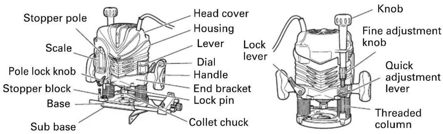
Fig. 1-1
Fig. 1-2
SPECIFICATIONS
| Model M12V2 M12SA2 | ||
| Motor Single Phase, Series Commutator Motor | ||
| Power source Single Phase 120V AC 60 Hz | ||
| Collet chuck capacity 1/2" (12.7 mm), 1/4" (6.35 mm) | ||
| Main Body Stroke 2-9/16' (65mm) | ||
| Current 15 A | ||
| No-load speed 8,000/min | -22,000/min 22,000/min | |
| Weight (without cord) 13.9 lbs (6.3 kg) 13.7 lbs (6.2 kg) | ||
ASSEMBLY AND OPERATION
APPLICATIONS
○Woodworking jobs centered on grooving and beveling.
For example, grooving beveling, cutting, copying, engraving, shape cutting, combinations and others.
PRIOR TO OPERATION
- Power source
Ensure that the power source to be utilized conforms to the power source requirements specified on the product nameplate.
- Power switch
Ensure that the switch is in the OFF position. If the plug is connected to a receptacle while the switch is in the ON position, the power tool will start operating immediately and can cause serious injury.
- Extension cord
When the work area is far away from the power source, use an extension cord of sufficient thickness and rated capacity. The extension cord should be kept as short as practicable.

natural_image
Black and white illustration of a hand with a lightning bolt symbol (no text or numbers)WARNING:
Damaged cord must be replaced or repaired.
- Check the receptacle
If the receptacle only loosely accepts the plug, the receptacle must be repaired. Contact a licensed electrician to make appropriate repairs.
If such a faultly receptacle is used, it may cause overheating, resulting in a serious hazard.
- Confirming condition of the environment
Confirm that the work site is placed under appropriate conditions conforming to prescribed precautions.
INSTALLING AND REMOVING BITS

WARNING: Be sure to switch power OFF and disconnect the plug from the receptacle to avoid serious trouble.
- Installing bits
(1) Clean and insert shank of bit into the collet chunk until shank bottoms, then back it out approximately 1/16" (approx. 2 mm).
(2) With the bit inserted and pressing the lock pin holding the armature shaft, use the 23 mm wrench to firmly tighten the collet chuck in a clockwise direction (viewed from under the router). (Fig. 2)
(3) When using the 1/4" diameter shank bit, replace the equipped collet chuck with the one for 1/4" diameter shank bit which is provided as the standard accessory.
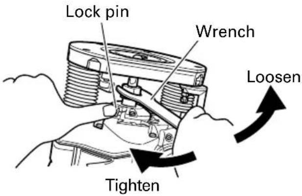
Fig. 2

CAUTION:
●Ensure that the collet chuck is firmly tightened after inserting a bit. Failure to do so will result in damage to the collet chuck.
●Ensure that the lock pin is not inserted into the armature shaft after tightening the collet chuck. Failure to do so will result in damage to the collet chuck, lock pin and armature shaft.
- Removing bits
When removing the bits, do so by following the steps for installing bits in reverse order.

CAUTION:
●Ensure that the lock pin is not inserted into the armature shaft after tightening a bit. Failure to do so will result in damage to the collet chuck, lock pin and armature shaft.
HOW TO USE THE ROUTER
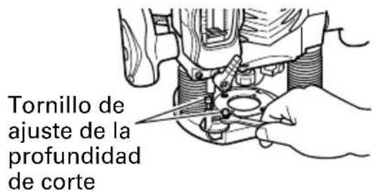
1. Adjusting depth of cut
(1) Place the tool on a flat wood surface.
(2) Turn the quick adjustment lever in a counterclockwise direction until the quick adjustment lever stops. (Fig. 4)
(3) Turn the stopper block so that section to which the cutting depth setting screw on a stopper block is not attached comes to the bottom of the stopper pole. Loosen pole lock knob allowing the stopper pole to contact with stopper block.
(4) Loosen the lock lever and press the tool body until the bit just touches the flat surface. Tighten the lock lever at this point. (Fig. 5)
(5) Tighten pole lock knob. Align the depth indicator with the "0" graduation of scale.
(6) Loosen pole lock knob, and raise until indicator aligns with the graduation representing the desired cutting depth. Tighten pole lock knob.
(7) Loosen the lock lever and press the tool body down until the stopper block to obtain the desired cutting depth.
Your router allows you to finely adjust depth of cut.
(1) Attach the accessory knob to fine adjustment knob. (Fig. 6)
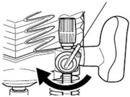
(2) Turn the quick adjustment lever in a clockwise direction until the quick adjustment lever stops with the stopper screw. (Fig. 7)
If the quick adjustment lever does not stop with the stopper screw, the bolt screw is not properly fitted.
If this occurs, slightly loosen the lock lever and press down on the unit (router) hard from the top and turn the quick adjustment lever again after properly fitting the bolt screw.
(3) The depth of cut can be adjusted when the lock lever is loosened, by turning the fine adjustment knob. Turning the fine adjustment knob counterclockwise results in a shallower cut, whereas turning it clockwise results in a deeper cut.
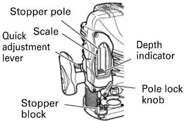
Fig. 3

Fig. 4
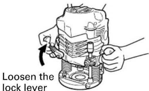
Fig. 5
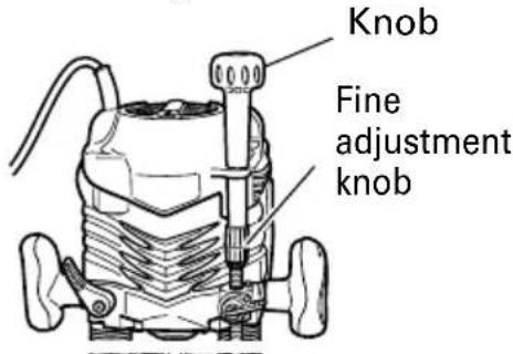
Fig. 6
CAUTION:
Ensure that the lock lever is tightened after finely adjusting depth of cut. Failure to do so will result in damage to the quick adjustment lever.
2. Stopper block (Fig. 8)
The 2 cut-depth setting screws attached to the stopper block can be adjusted to simultaneously set 3 different cutting depth. Use a wrench to tighten the nuts so that the cut-depth setting screws do not come loose at this time.
3. Guiding the router
WARNING: Be sure to switch power OFF and disconnect the plug from the receptacle to avoid serious trouble.
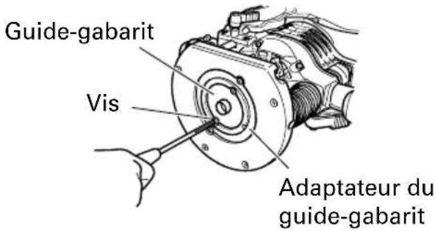
(1) Template guide adapter
①Loosen the 2 template guide adapter screws, so that the template guide adapter can be moved. (Fig. 9)
②Insert the centering gauge through the hole in the template guide adapter and into the collet chuck. (Fig. 10)
③Tighten the collet chuck by hand.
④ Tighten the template guide adapter screws, and pull out the centering gauge.
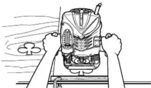
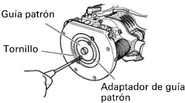
(2) Template guide
Use the template guide when employing a template for producing a large quantity of identically shaped products. (Fig. 11)
As shown in Fig. 12, to install insert template guide in center hole in template guide adapter (A) with 2 accessory screws.
If you are using a template guide adapter (B), it is possible to use template guides produced by other firms. Attach template guides made by other firms to the template guide adapter (B).
A template is a profiling mold made of plywood or thin lumber. When making a template, pay particular attention to the matters described below and illustrated in Fig. 13.
Quick adjustment lever
natural_image
Diagram of a mechanical device with motion lines indicating motion, no text or symbols presentFig. 7
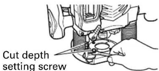
Fig. 8
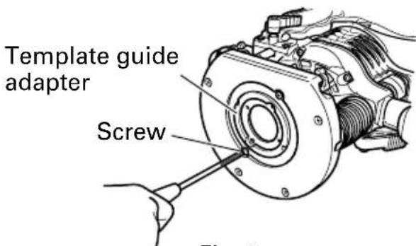
Fig. 9
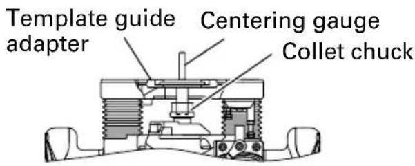
Fig. 10
natural_image
Line drawing of hands operating a mechanical device with a clover symbol nearby (no text or labels)Fig. 11
When using the router along the interior plane of the template, the dimensions of the finished product will be less than the dimensions of the template by an amount equal to dimension "A", the difference between the radius of the template guide and the radius of the bit. The reverse is true when using the router along the exterior of the template.
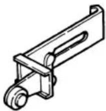
(3) Straight guide (Fig.14)
Use straight guide for chamfering and groove cutting along the materials side.
①Insert the guide bar into the hole in the bar holder, then lightly tighten the 2 wing bolts (B) on top of the bar holder.
②Insert the guide bar into the hole in the base, then firmly tighten the wing bolts (A) (standard accessories).
③Make minute adjustments of the dimensions between the bit and the guide surface with the feed screw, then firmly tighten the 2 wing bolts (B) on top of the bar holder and the wing bolt (C) that secures the straight guide.
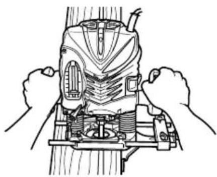
④As shown in Fig. 15, securely attach the bottom of the base to processed surface of the materials. Feed the router while keeping the guide plane on the surface of the materials.
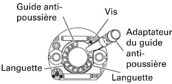
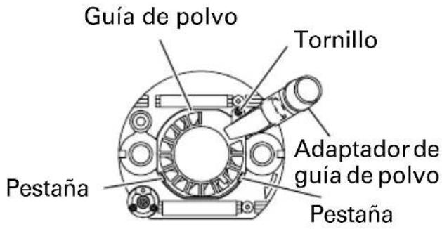
(4) Dust guide and dust guide adapter (Fig. 16) Your router is equipped with a dust guide and a dust guide adapter.
①Match the 2 grooves on the base and insert the 2 dust guide tabs in holes located in the base side from the top. Tighten the dust guide with a screw.
The dust guide diverts cutting debris away from the operator and directs the discharge in a consistent direction.
②By fitting the dust guide adapter into the dust guide cutting debris discharge vent, the dust extractor can be attached.
- Adjusting the rotation speed (Model M12V2 only)
The M12V2 has an electronic control system that allows stepless rpm changes. As shown in Fig. 17, dial position "1" is for minimum speed, and position "6" for maximum speed.
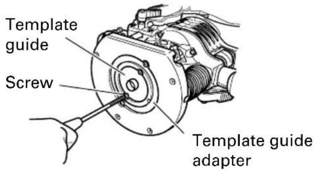
Fig. 12
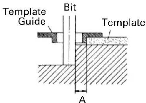
Fig. 13
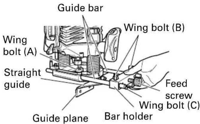
Fig. 14
natural_image
Line drawing of hands operating a mechanical device with no visible text or symbolsFig. 15
5. Removing the spring
The springs within the column of the router can be removed. Doing so will eliminate spring resistance and allows easy adjustment of cutting depth when attaching the router stand.
(1) Loosen the 4 sub base screws, and remove the sub base.
(2) Loosen the stopper bolt and remove it, so the spring can be removed. (Fig. 18)
WARNING:
Remove the stopper bolt with the main unit (router) fixed at its maximum height.
Removing the stopper bolt with the unit in a shortened condition may cause the stopper bolt and spring to be discharged and cause injury.
6. Cutting
WARNING:
●Wear eye protection when operating this tool.
- Keep your hands, face and other body parts away from the bits and any other rotating parts, while operating the tool.
(1) As shown in Fig. 19, remove the bit from the work pieces and press the switch lever up to the ON position. Do not start cutting operation until the bit has reached full rotating speed.
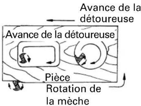
(2) The bit rotates clockwise (arrow direction indicated on the base). To obtain maximum cutting effectiveness, feed the router in conformance with the feed directions shown in Fig. 20.
NOTE:
If a worn bit is used to make deep grooves, a high pitched cutting noise may be produced.
Replacing the worn bit with a new one will eliminate the high pitched noise.
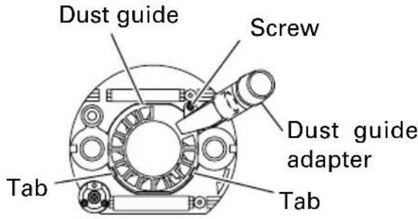
Fig. 16
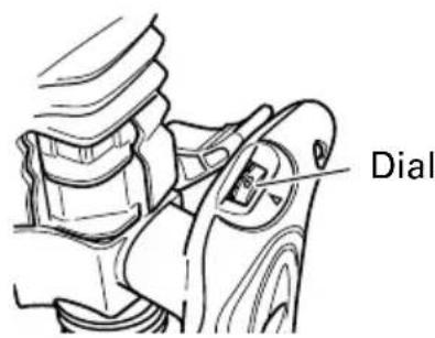
Fig. 17
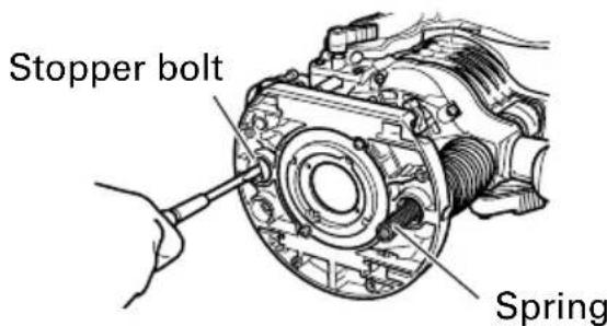
Fig. 18

Fig. 19

flowchart
graph TD
    A["Router feed"] --> B["Workpiece"]
    B --> C["Rotation of bit"]
    style A fill:#f9f,stroke:#333
    style B fill:#ccf,stroke:#333
    style C fill:#cfc,stroke:#333
Fig. 20
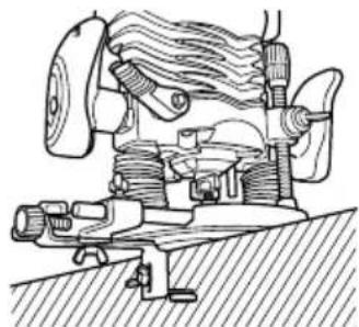
USING THE OPTIONAL ACCESSORIES
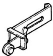
Trimmer Guide
Use the trimmer guide for chamfering.
As shown in Fig. 21 use the wing bolt to mount and secure the trimmer guide on the bar holder.
Use the two wing bolts to align the trimmer guide in the desired position, and use it as shown in Fig. 22.
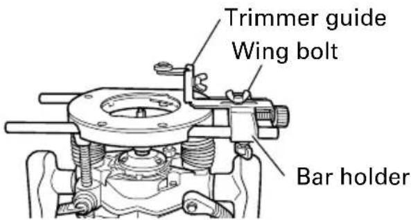
Fig. 21
natural_image
Technical line drawing of a mechanical assembly with no visible text or symbolsFig. 22
NOTE:
● Moving the tool forward fast may cause a poor quality of cut, or damage to the bit or motor. Moving the tool forward too slowly may burn and mar the cut.
The proper feed rate will depend on the bit size, the kind of workpiece and depth of cut. Before beginning the cut on the actual workpiece, it is advisable to make a sample cut on a piece of scrap lumber. This will show exactly how the cut will look as well as enable you to check dimensions.
●Abnormalities and overloads will trigger the overload protector, and stop operation.
Remove the load immediately, and turn the power off, then on. The rotation speed should return to normal.
- Do not use a power generator as the power source. It may cause the rotation speed to fluctuate.
- When using the straight guide, be sure to install it on the right side in the feed direction. This will help to keep it flush with the side of the workpiece.
MAINTENANCE AND INSPECTION

WARNING: Be sure to switch power OFF and disconnect the plug from the receptacle during maintenance and inspection.
- Inspecting the screws
Regularly inspect all screws and ensure that they are fully tightened. Should any of the screws be loosened, retighten them immediately.

WARNING: Using this router with loosened screws is extremely dangerous.
- Maintenance of the motor
The motor unit winding is the very “heart” of the power tool. Exercise due care to ensure the winding does not become damaged and/or wet with oil or water.
- Service and repairs
All quality power tools will eventually require servicing or replacement of parts because of wear from normal use. To assure that only authorized replacement parts will be used, all service and repairs must be performed by a metabo HPT AUTHORIZED SERVICE CENTER, ONLY.
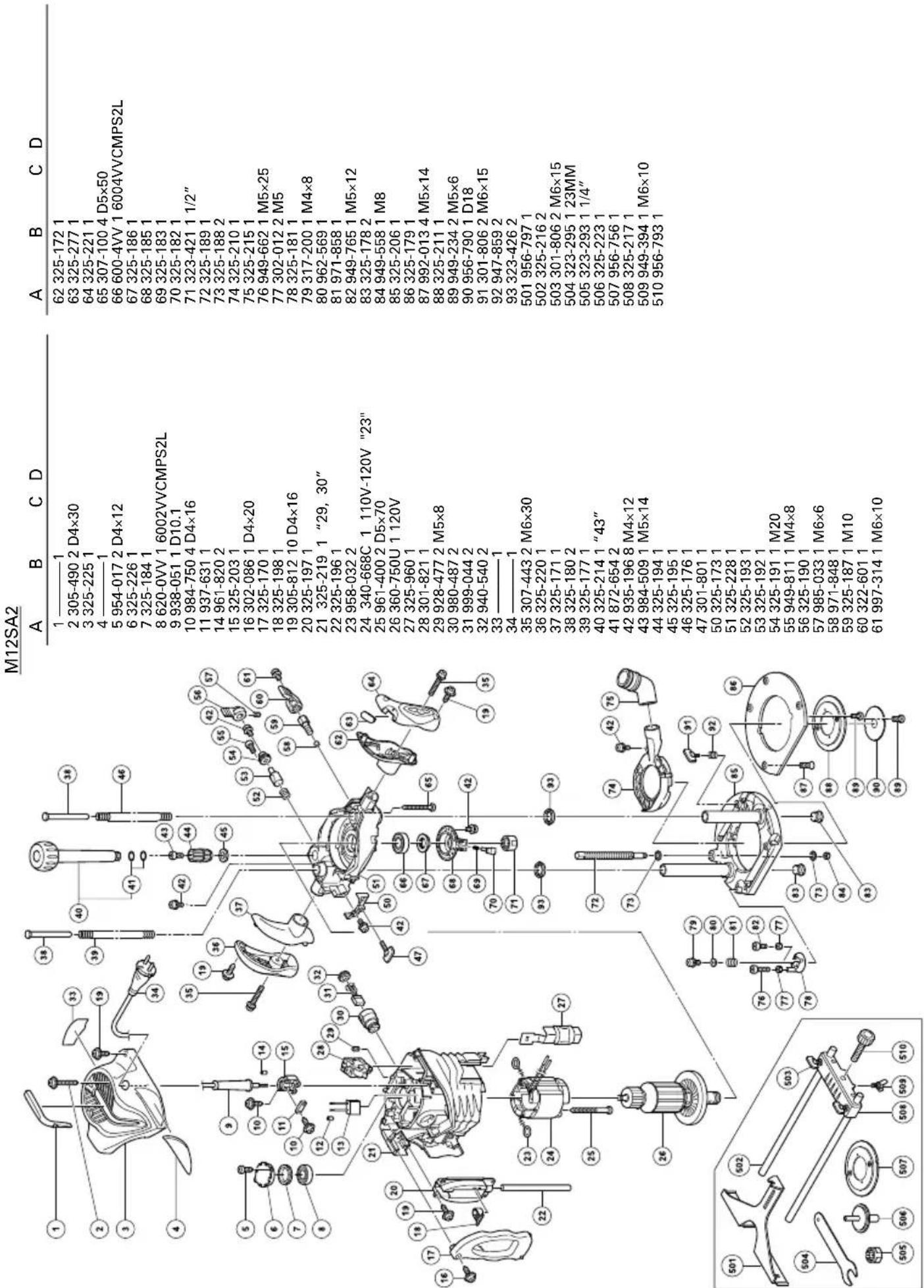
- Service parts list
A: Item No.
B: Code No.
C: No. Used
D: Remarks

CAUTION: Repair, modification and inspection of metabo HPT Power Tools must be carried out by a metabo HPT Authorized Service Center.
This Parts List will be helpful if presented with the tool to the metabo HPT Authorized Service Center when requesting repair or other maintenance. In the operation and maintenance of power tools, the safety regulations and standards prescribed in each country must be observed.
MODIFICATIONS:
metabo HPT Power Tools are constantly being improved and modified to incorporate the latest technological advancements.
Accordingly, some parts (i.e. code numbers and/or design) may be changed without prior notice.
ACCESSORIES

WARNING:
ALWAYS use Only authorized metabo HPT replacement parts and accessories. NEVER use replacement parts or accessories which are not intended for use with this tool. Contact metabo HPT if you are not sure whether it is safe to use a particular replacement part or accessory with your tool. The use of any other attachment or accessory can be dangerous and could cause injury or mechanical damage.
NOTE:
Accessories are subject to change without any obligation on the part of the metabo HPT.
STANDARD ACCESSORIES
(1) 1/4" Collet Chuck (Code No. 323-293)....1
(2) Template Guide Adapter (A) (attaches to the router) (Code No. 325-211) .... 1
(3) Template Guide Adapter (B) (Code No. 325-224) ...... 1
(4) Template Guide (Code No. 956-790) .... 1
(5) Centering Gauge (Code No. 325-223) 1
(6) Dust Guide (Code No. 325-210)....1
(7) Dust Guide Adapter (Code No. 325-215) .... 1
(8) Bar Holder (Code No. 325-217)....1
Straight Guide (Code No. 956-797) .... 1
Feed Screw (Code No. 956-793) 1
Wing Bolt (Code No. 949-394) 1
(9) Guide Bar (Code No. 325-216) 2
(10)Knob (Code No. 325-214) 1
(11)Wing Bolt (Code No. 301-806) 4
(12)23 mm Wrench (Code No. 323-295) 1
OPTIONAL ACCESSORIES .... sold separately
(1) Template Guide (2) Trimmer Guide (Code No. 956-794)
natural_image
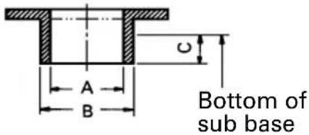
Technical line drawing of a mechanical bracket or clamp (no text or symbols)| Code No. | A B C | ||
| 303 347 1 | 9/64" 3/8"(7.5mm) (9.5mm) | ||
| 303 348 5 | /16" 25/64"(8mm) (10mm) | ||
| 303 349 2 | 3/64" 7/16"(9mm) (11.1mm) | ||
| 303 350 2 | 5/64" 15/32"(10mm) (12mm) | ||
| 303 351 2 | 7/64" 1/2"(10.7mm) (12.7mm) | ||
| 303 352 1 | 5/32" 35/64"(12mm) (14mm) | ||
| 303 353 3 | 5/64" 5/8" 3/16"(14mm) (16mm) (4.5mm) | ||
| 956 790 2 | 1/32" 45/64"(16.5mm) (18mm) | ||
| 956 932Z | 47/64" 25/32"(18.5mm) (20mm) | ||
| 303 354 5 | 7/64" 15/16"(22.5mm) (24mm) | ||
| 956 933Z | 1"(25.5mm) | 1-1/16"(27mm) | |
| 956 934Z | 1-1/8" 1-(28.5mm) | 3/16"(30mm) | |
| 303 355 | 1-33/64"(38.5mm) | -37/64"(40mm) |
(3) Chuck Sleeve
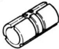
3/8" (9.5mm)
(Code No. 956-928Z)
NOTE:
Specifications are subject to change without any obligation on the part of the metabo HPT.
CONSIGNES DE SÉCURITÉ IMPORTANTES
natural_image
Black and white illustration of a hand with a lightning bolt symbol (no text or numbers)⚠ AVERTISSEMENT:
natural_image
Line drawing of hands assembling a small electronic device with circuit board and vent, no text or symbols presentFig. 11
natural_image
Line drawing of hands operating a mechanical device with no visible text or symbolsFig. 15
natural_image
Technical line drawing of a mechanical assembly with hands holding parts (no text or symbols)Séparation
Fig. 19
natural_image
Technical line drawing of a mechanical assembly with no visible text or symbolsFig. 22
REMARQUE :
(No. de code 956-794)
natural_image
Technical line drawing of a mechanical bracket or clamp (no text or symbols)(3) Douille -mandrin
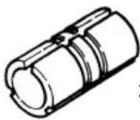
3/8" (9.5mm)
(No. de code 956-928Z)
REMARQUE:
natural_image
Black and white illustration of a hand with a lightning bolt symbol (no text or numbers)ADVERTENCIA:
natural_image
Mechanical diagram showing a lever mechanism with a rotating component and a base, no text or symbols present.Fig. 7
natural_image
Line drawing of hands operating a machine with a clover symbol on the floor (no text or labels)Fig. 11
natural_image
Line drawing of hands operating a mechanical device with no visible text or symbolsFig. 15
natural_image
Technical line drawing of a mechanical assembly with no visible text or symbolsFig. 22
NOTA:
natural_image
Technical line drawing of a mechanical bracket or clamp (no text or symbols)(3) Manguito mandril

natural_image
Line drawing of a quill pen in an inkwell (no text or symbols)
natural_image
Line drawing of a quill pen in an inkwell (no text or symbols)
natural_image
Line drawing of a quill pen in an inkwell (no text or symbols)WARNING:
Some dust created by power sanding, sawing, grinding, drilling, and other construction activities contains chemicals known to the State of California to cause cancer, birth defects or other reproductive harm. Some examples of these chemicals are:
- Lead from lead-based paints,
●Crystalline silica from bricks and cement and other masonry products, and
●Arsenic and chromium from chemically-treated lumber.
Your risk from these exposures varies, depending on how often you do this type of work. To reduce your exposure to these chemicals: work in a well ventilated area, and work with approved safety equipment, such as those dust masks that are specially designed to filter out microscopic particles.
AVERTISSEMENT:
Minato-ku, Tokyo 108-6020, Japan
Distributed by
Koki Holdings America Ltd.
1111 Broadway Ave,
Braselton, Georgia, 30517
Koki Holdings America Ltd. Canadian Branch
3405 American Drive, Units 9-10,
Mississauga, ON, L4V 1T6
806
Code No. C99145264 M
Printed in Malaysia


- SAFETY INSTRUCTIONS AND INSTRUCTION MANUAL
- WARNING
- INSTRUCTIONS DE SECURITE ET MODE D'EMPLOI
- ⚠ AVERTISSEMENT
- TABLE DES MATIERES
- Français
- IMPORTANT SAFETY INSTRUCTIONS
- MEANINGS OF SIGNAL WORDS
- SAFETY
- GENERAL POWER TOOL SAFETY WARNINGS
- SPECIFIC SAFETY RULES AND SYMBOLS
- USE OF EXTENSION CORD
- WARNING:
- SAVE THESE INSTRUCTIONS
- AND
- MAKE THEM AVAILABLE TO
- OTHER USERS
- OWNERS OF THIS TOOL!
- FUNCTIONAL DESCRIPTION
- NOTE:
- NAME OF PARTS
- ASSEMBLY AND OPERATION
- APPLICATIONS
- PRIOR TO OPERATION
- INSTALLING AND REMOVING BITS
- CAUTION:
- HOW TO USE THE ROUTER
- Adjusting depth of cut
- Stopper block (Fig. 8)
- Guiding the router
- Removing the spring
- Cutting
- USING THE OPTIONAL ACCESSORIES
- Trimmer Guide
- MAINTENANCE AND INSPECTION
- MODIFICATIONS:
- ACCESSORIES
- STANDARD ACCESSORIES
- OPTIONAL ACCESSORIES .... sold separately
- CONSIGNES DE SÉCURITÉ IMPORTANTES
- ⚠ AVERTISSEMENT:
- REMARQUE :
- REMARQUE:
- ADVERTENCIA:
- NOTA:
- AVERTISSEMENT:
- Koki Holdings America Ltd.
- Koki Holdings America Ltd. Canadian Branch
Brand : METABO
Model : M 12V2
Category : Milling machine