V1200HD - Video switch ROLAND - Free user manual and instructions
Find the device manual for free V1200HD ROLAND in PDF.

User questions about V1200HD ROLAND
0 question about this device. Answer the ones you know or ask your own.
Ask a new question about this device
Download the instructions for your Video switch in PDF format for free! Find your manual V1200HD - ROLAND and take your electronic device back in hand. On this page are published all the documents necessary for the use of your device. V1200HD by ROLAND.
USER MANUAL V1200HD ROLAND
MULTI-FORMAT VIDEO SWITCHER
V-1200HD
Owner's Manual
Ver. 1.2 and Later

Owner's Manual (this document)
Read this first. It explains the basic things you need to know in order to use the V-1200HD.

PDF Manual (download from the Web)
•V-1200HDR/V-1200HD RCS Remote Control Guide
This explains the procedures and settings when using the V-1200HDR or V-1200HD RCS remote-control software to operate the unit.
Copyright © 2016 ROLAND CORPORATION

To obtain the PDF manual
- Enter the following URL in your computer.
https://proav.roland.com/manuals/

- Choose "V-1200HD" as the product name.

WARNING: To reduce the risk of fire or electric shock, do not expose this apparatus to rain or moisture.

ATTENTION
CAUTION
RISK OF ELECTRIC SHOCK
DO NOT OPEN

RISQUE DE CHOC ELECTRIQUE NE PAS OUVRIR
CAUTION: TO REDUCE THE RISK OF ELECTRIC SHOCK, DO NOT REMOVE COVER (OR BACK). NO USER-SERVICEABLE PARTS INSIDE. REFER SERVICING TO QUALIFIED SERVICE PERSONNEL.

The lightning flash with arrowhead symbol, within an equilateral triangle, is intended to alert the user to the presence of uninsulated “dangerous voltage” within the product's enclosure that may be of sufficient magnitude to constitute a risk of electric shock to persons.

The exclamation point within an equilateral triangle is intended to alert the user to the presence of important operating and maintenance (servicing) instructions in the literature accompanying the product.
INSTRUCTIONS PERTAINING TO A RISK OF FIRE, ELECTRIC SHOCK, OR INJURY TO PERSONS.
IMPORTANT SAFETY INSTRUCTIONS SAVE THESE INSTRUCTIONS
WARNING - When using electric products, basic precautions should always be followed, including the following:
- Read these instructions.
- Keep these instructions.
- Heed all warnings.
- Follow all instructions.
- Do not use this apparatus near water.
- Clean only with a dry cloth.
- Do not block any of the ventilation openings. Install in accordance with the manufacturers instructions.
- Do not install near any heat sources such as radiators, heat registers, stoves, or other apparatus (including amplifiers) that produce heat.
-
Do not defeat the safety purpose of the polarized or grounding-type plug. A polarized plug has two blades with one wider than the other. A grounding type plug has two blades and a third grounding prong. The wide blade or the third prong are provided for your safety. If the provided plug does not fit into your outlet, consult an electrician for replacement of the obsolete outlet.
-
Protect the power cord from being walked on or pinched particularly at plugs, convenience receptacles, and the point where they exit from the apparatus.
- Only use attachments/accessories specified by the manufacturer.
- Unplug this apparatus during lightning storms or when unused for long periods of time.
- Refer all servicing to qualified service personnel. Servicing is required when the apparatus has been damaged in any way, such as power-supply cord or plug is damaged, liquid has been spilled or objects have fallen into the apparatus, the apparatus has been exposed to rain or moisture, does not operate normally, or has been dropped.
-For the U.K.
WARNING: THIS APPARATUS MUST BE EARTHED
IMPORTANT: THE WIRES IN THIS MAINS LEAD ARE COLOURED IN ACCORDANCE WITH THE FOLLOWING CODE. GREEN-AND-YELLOW: EARTH, BLUE: NEUTRAL, BROWN: LIVE
As the colours of the wires in the mains lead of this apparatus may not correspond with the coloured markings identifying the terminals in your plug, proceed as follows:
The wire which is coloured GREEN-AND-YELLOW must be connected to the terminal in the plug which is marked by the letter E or by the safety earth symbol ↓ or coloured GREEN or GREEN-AND-YELLOW.
The wire which is coloured BLUE must be connected to the terminal which is marked with the letter N or coloured BLACK. The wire which is coloured BROWN must be connected to the terminal which is marked with the letter L or coloured RED.
INSTRUCTIONS FOR THE PREVENTION OF FIRE, ELECTRIC SHOCK, OR INJURY TO PERSONS
About ⚠️ WARNING and ⚠️ CAUTION Notices
| WARNING | Used for instructions intended to alert the user to the risk of death or severe injury should the unit be used improperly. |
| CAUTION | Used for instructions intended to alert the user to the risk of injury or material damage should the unit be used improperly.* Material damage refers to damage or other adverse effects caused with respect to the home and all its furnishings, as well to domestic animals or pets. |
About the Symbols
| [×0×46] | The △symbol alerts the user to important instructions or warnings. The specific meaning of the symbol is determined by the design contained within the triangle. In the case of the symbol at left, it is used for general cautions, warnings, or alerts to danger. |
| [×1×035] | The ⚙symbol alerts the user to items that must never be carried out (are forbidden). The specific thing that must not be done is indicated by the design contained within the circle. In the case of the symbol at left, it means that the unit must never be disassembled. |
| [×2×74] | The ●symbol alerts the user to things that must be carried out. The specific thing that must be done is indicated by the design contained within the circle. In the case of the symbol at left, it means that the power-cord plug must be unplugged from the outlet. |
ALWAYS OBSERVE THE FOLLOWING

WARNING
Make sure that the power cord is grounded
Connect mains plug of this model to a mains socket outlet with a protective earthing connection.

To completely turn off power to the unit, pull out the plug from the outlet
Even with the power switch turned off, this unit is not completely separated from its main source of power. When the power needs to be completely turned off, turn off the power switch on the unit, then pull out from the outlet. For this reason, the outlet is you choose to connect the power cord's plu be one that is within easy reach and readily

Secure a sufficient amount of space at the setup location
This unit has internal fans for cooling. To ensure proper cooling, install the unit with enough surrounding space to ensure that the unit's ventilation ports are not obstructed.

Do not disassemble or modify by yourself
Do not carry out anything unless you are instructed to do so in the owner's manual. Otherwise, you risk causing malfunction.

Do not repair or replace parts by yourself
Refer all servicing to your retailer, the nearest Roland Service Center, or an authorized Roland distributor, as listed on the "Information."


WARNING
Do not use or store in the following types of locations
- Subject to temperature extremes (e.g., direct sunlight in an enclosed vehicle, near a heating duct, on top of heat-generating equipment); or are
- Damp (e.g., baths, washrooms, on wet floors); or are
• Exposed to steam or smoke; or are
• Subject to salt exposure; or are - Exposed to rain; or are
• Dusty or sandy; or are - Subject to high levels of vibration and shakiness.


Do not place in an unstable location
Otherwise, you risk injury as the result of the unit toppling over or dropping down.

Use only the supplied power cord
Use only the attached power cord. Also, the supplied power cord must not be used with any other device.

Connect the power cord to an outlet of the correct voltage
The unit should be connected to a power supply only of the type described in the operating instructions, or as marked on the side of unit.

Do not bend the power cord or place heavy objects on it
Otherwise, fire or electric shock may result.

Avoid extended use at high volume
Use of the unit at high volume for extended periods of time may cause hearing loss. If you ever experience any hearing loss or ringing in the ears, you should immediately stop using the unit and consult a specialized physician.


WARNING
Do not allow foreign objects or liquids to enter unit; never place containers with liquid on unit
Do not place containers containing liquid (e.g., flower vases) on this product. Never allow foreign objects (e.g., flammable objects, coins, wires) or liquids (e.g., water or juice) to enter this product. Doing so may cause short circuits, faulty operation, or other malfunctions.


Turn off the unit if an abnormality or malfunction occurs
Immediately turn the unit off, remove the power cord from the outlet, and request servicing by your retailer, the nearest Roland Service Center, or an authorized Roland distributor, as listed on the "Inform

• The power cord has been damaged; or
• If smoke or unusual odor occurs; or
- Objects have fallen into, or liquid has been spilled onto the unit; or
- The unit has been exposed to rain (or otherwise has become wet); or
- The unit does not appear to operate normally or exhibits a marked change in performance.
Do not drop or subject to strong impact
Otherwise, you risk causing damage or malfunction.

Do not share an outlet with an unreasonable number of other devices
Otherwise, you risk overheating or fire.

Do not use overseas
Before using the unit in overseas, consult with your retailer, the nearest Roland Service Center, or an authorized Roland distributor, as listed on the "Information."

Turn the unit off before installing expansion interface
Before installing the expansion interface, you must first always turn off the unit and unplug its power cord.

CAUTION
Place in a well ventilated location
The unit should be located so that its location or position does not interfere with its proper ventilation.

When disconnecting the power cord, grasp it by the plug
To prevent conductor damage, always grasp the power cord by its plug when disconnecting it from this unit or from a power outlet.

Periodically clean the power plug
An accumulation of dust or foreign objects between the power plug and the power outlet can lead to fire or electric shock.

At regular intervals, be sure to pull out the power plug, and using a dry cloth, wipe away any dust or foreign objects that may have accumulated.
Disconnect the power plug whenever the unit will not be used for an extended period of time
Fire may result in the unlikely event that a breakdown occurs.

Route all power cords and cables in such a way as to prevent them from getting entangled
Injury could result if someone were to trip on a cable and cause the unit to fall or topple.

Avoid climbing on top of the unit, or placing heavy objects on it
Otherwise, you risk injury as the result of the unit toppling over or dropping down.

Never connect/disconnect a power plug if your hands are wet
Otherwise, you could receive an electric shock.

Disconnect all cords/cables before moving the unit
Before moving the unit, disconnect the power plug from the outlet, and pull out all cords from external devices.

CAUTION
Before cleaning the unit, disconnect the power plug from the outlet
If the power plug is not removed from the outlet, you risk receiving an electric shock.

Whenever there is a threat of lightning, disconnect the power plug from the outlet
If the power plug is not removed from the outlet, you risk receiving an electric shock.

Install only specified circuit expansion interface
Install only the specified expansion interface XI series. Remove only the specified screws (p.14).

Keep small items out of the reach of children
To prevent accidental ingestion of the parts listed below, always keep them out of the reach of small children.

• Included Parts
Rubber feet (p.14)
- Removable Parts
Power-cord hook
Screw for Power-cord hook (p.12)
Screws for face panel (p.10)
Handle the ground terminal carefully
If you remove the screw from the ground terminal, be sure to replace it; don't leave it lying around where it could accidentally be swallowed by small children. When refastening the screw, make that it is firmly so it won't come loose.

Take care not to get burned
The unit may become hot, so take care to avoid burns.

INSTRUCTIONS POUR LA PRÉVENTION DES INCENDIES, CHOCS ÉLECTRIQUES OU BLESSURES
- Do not connect this unit to same electrical outlet that is being used by an electrical appliance that is controlled by an inverter or a motor (such as a refrigerator, washing machine, microwave oven, or air conditioner). Depending on the way in which the electrical appliance is used, power supply noise may cause this unit to malfunction or may produce audible noise. If it is not practical to use a separate electrical outlet, connect a power supply noise filter between this unit and the electrical outlet.
- If the unit has been used with a power supply that has not been specified as suitable for the unit, the subsequent performance and operation of the unit can no longer be guaranteed. Also note that we may not be able to accept the unit for servicing and repairs.
Placement
- Using the unit near power amplifiers (or other equipment containing large power transformers) may induce hum. To alleviate the problem, change the orientation of this unit; or move it farther away from the source of interference.
- This unit may interfere with radio and television reception. Do not use this unit in the vicinity of such receivers.
- Noise may be produced if wireless communications devices, such as cell phones, are operated in the vicinity of this unit. Such noise could occur when receiving or initiating a call, or while conversing. Should you experience such problems, you should relocate such wireless devices so they are at a greater distance from this unit, or switch them off.
- Do not expose the unit to direct sunlight, place it near devices that radiate heat, leave it inside an enclosed vehicle, or otherwise subject it to temperature extremes. Excessive heat can deform or discolor the unit.
- When moved from one location to another where the temperature and/or humidity is very different, water droplets (condensation) may form inside the unit. Damage or malfunction may result if you attempt to use the unit in this condition. Therefore, before using the unit, you must allow it to stand for several hours, until the condensation has completely evaporated.
- Depending on the material and temperature of the surface on which you place the unit, its rubber feet may discolor or mar the surface. You can place a piece of felt or cloth under the rubber feet to prevent this from happening. If you do so, please make sure that the unit will not slip or move accidentally.
- Do not place containers or anything else containing liquid on top of this unit. Also, whenever any liquid has been spilled on the surface of this unit, be sure to promptly wipe it away using a soft, dry cloth.
Maintenance
- For everyday cleaning wipe the unit with a soft, dry cloth or one that has been slightly dampened with water. To remove stubborn dirt, use a cloth impregnated with a mild, non-abrasive detergent. Afterwards, be sure to wipe the unit thoroughly with a soft, dry cloth.
- Never use benzine, thinners, alcohol or solvents of any kind, to avoid the possibility of discoloration and/or deformation.
Repairs and Data
- Before sending the unit away for repairs, be sure to make a backup of the data stored within it; or you may prefer to write down the needed information. Although we will do our utmost to preserve the data stored in your unit when we carry out repairs, in some cases, such as when the memory section is physically damaged, restoration of the stored content may be impossible. Roland assumes no liability concerning the restoration of any stored content that has been lost.
Additional Precautions
- Any data stored within the unit can be lost as the result of equipment failure, incorrect operation, etc. To protect yourself against the irretrievable loss of data, try to make a habit of creating regular backups of the data you've stored in the unit.
- Roland assumes no liability concerning the restoration of any stored content that has been lost.
- Use a reasonable amount of care when using the unit's buttons, sliders, or other controls; and when using its jacks and connectors. Rough handling can lead to malfunctions.
- When disconnecting all cables, grasp the connector itself—never pull on the cable. This way you will avoid causing shorts, or damage to the cable's internal elements.
- A small amount of heat will radiate from the unit during normal operation.
- To avoid disturbing others nearby, try to keep the unit's volume at reasonable levels.
- When you need to transport the unit, pack it in shock-absorbent material. Transporting the unit without doing so can cause it to become scratched or damaged, and could lead to malfunction.
- This unit allows you to switch images at high speed. For some people, viewing such images can cause headache, nausea, or other discomfort. Do not use this unit to create video that might cause these types of health problems. Roland Corporation will accept no responsibility for any such health problems that may occur in yourself or in viewers.
Using External Memories
- Please observe the following precautions when handling external memory devices. Also, make sure to carefully observe all the precautions that were supplied with the external memory device.
- Do not remove the device while reading/writing is in progress.
• To prevent damage from static electricity, discharge all static electricity from your person before handling the device.
Intellectual Property Right
- It is forbidden by law to make an audio recording, video recording, copy or revision of a third party's copyrighted work (musical work, video work, broadcast, live performance, or other work), whether in whole or in part, and distribute, sell, lease, perform, or broadcast it without the permission of the copyright owner.
- Do not use this product for purposes that could infringe on a copyright held by a third party. We assume no responsibility whatsoever with regard to any infringements of third-party copyrights arising through your use of this product.
- MMP (Moore Microprocessor Portfolio) refers to a patent portfolio concerned with microprocessor architecture, which was developed by Technology Properties Limited (TPL). Roland has licensed this technology from the TPL Group.
- This product is using the open source license (GPL/LGPL) software. You have the right to acquire, modify and distribute the source code for this open source license software. You can obtain the open source license source code used in this product by downloading it from the following website: URL:http://www.roland.com/support/gpl/
- This product contains eCROS integrated software platform of eSOL Co., Ltd. eCROS is a trademark of eSOL Co., Ltd. in Japan.
- Roland, V-Mixer are either registered trademarks or trademarks of Roland Corporation in the United States and/or other countries.
- Company names and product names appearing in this document are registered trademarks or trademarks of their respective owners.
- VISCA is a protocol developed by Sony for controlling a consumer's camcorder. "VISCA" is a trademark of Sony Corporation.
USING THE UNIT SAFELY 4
CONSIGNES DE SÉCURITÉ French Language
for Canadian Safety Standard
IMPORTANT NOTES 8
Placement and Setup.... 10
Important Notes on Installation 10
Important Notes on Rack Mounting.... 10
Connecting the Power Cord.... 10
Using the Power Cord Hook.... 12
Using an External Power Source 12
Turning the Power On and Off.... 12
Installing an Expansion Interface (Option) 14
Attaching the Rubber Feet.... 14
Installation et Configuration French language for Canadian Safety Standard
Remarques importantes concernant l'installation.... 11
Part Names and Functions.... 16
Front Panel 16
Rear Panel 17
Internal Structure of the V-1200HD.... 19
About Processing Formats.... 19
About HDMI IN 3 and 4.... 20
About Copyright Protection (HDCP) 20
Connecting External Equipment.... 21
Connecting Source Equipment.... 23
Connecting Video Source Equipment.... 23
Connecting Audio Source Equipment.... 24
Connecting a Reference.... 24
Connecting Output Equipment 25
Connecting Video Output Equipment 25
Connecting Audio Output Equipment 25
Setup Menu 26
Using the Menus 26
Menu Organization 26
Remote Control from an External Device 27
Using a V-1200HDR Dedicated Controller 27
Using V-1200HD RCS Dedicated Software.... 27
RS-232 Connector Specifications 28
Using the TALLY/GPIO Connector.... 28
Other Features.... 29
Operating a VISCA-Compatible Video Camera by Remote Control .... 29
About the TALLY/GPIO Connector 29
Saving/Recalling Settings.... 30
Checking the Version Information 30
Formatting a USB Flash Drive 30
Returning Settings to the Factory-Default State (Factory Reset).... 30
Appendix.... 31
Troubleshooting 31
Main Specifications 32
Dimensions.... 33
Block Diagram 34
Before using this unit, carefully read the sections entitled "IMPORTANT SAFETY INSTRUCTIONS" (p. 2), "USING THE UNIT SAFELY" (p. 4), and "IMPORTANT NOTES" (p. 8). These sections provide important information concerning the proper operation of the unit. Additionally, in order to feel assured that you have gained a good grasp of every feature of your new unit, read this Owner's Manual in its entirety. This manual should be saved and kept on hand as a convenient reference.
Checking the Included Items
The following items are included with this unit. Check to make sure that all items are present. If anything is missing, contact your dealer.
□ The unit

natural_image
Front view of a black electronic device with control buttons and indicator lights (no readable text or symbols)□ Power cord

* The shape of the power cord's plug varies depending on the country.
□ Rubber feet (4)

□ Owner's Manual
Important Notes on Installation

- Never insert your fingers or other objects into the space between the unit's front face panel and the body of the unit. Doing so might lead to injury.
- When detaching the face panel, to ensure safety, turn off the power and disconnect the power plug from the electrical outlet.
- Use with the face panel detached is dangerous and must never be attempted.
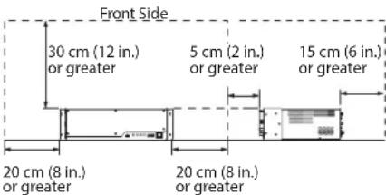
When installing the V-1200HD, never block or place objects next to the ventilation ports, and avoid obstructing the space between the face panel and the unit. Otherwise, the temperature inside the V-1200HD could rise and create the risk of malfunction due to heat. Refer to the figure below for the locations of the ventilation ports.
natural_image
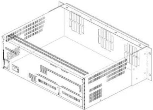
Isometric line drawing of a server rack unit with ventilation grilles and ventilation grilles (no text or labels)* The openings are ventilation ports.
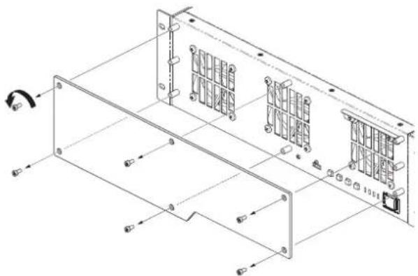
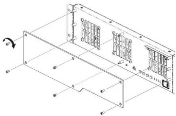
Dust buildup in the ventilation ports can impede heat radiation and cooling of the V-1200HD, resulting in malfunction. Regularly check the ports and clear away any buildup of dust or other material. For the ventilation ports on the front of the V-1200HD, use the procedure shown below to remove the face panel and clear away any dust.
- Use a hex wrench (3 mm across flats) to loosen the mounting screws (6) specified in the figure and detach the face panel.
natural_image
Technical line drawing of a server rack frame with mounting holes and ventilation slots (no text or symbols)-
Clear away any dust buildup from the ventilation ports.
-
Use the mounting screws (6) as shown to secure the face panel in place again.
natural_image
Technical line drawing of a mechanical assembly with mounting brackets and internal components (no text or symbols)Important Notes on Rack Mounting
* When mounting the V-1200HD in a rack enclosure, pay attention to the following points to ensure efficient cooling.
• Install in a well-ventilated location.
- Avoid blocking the cooling-fan exhaust ports in the top, rear, and side panels of the V-1200HD.
- Avoid mounting the unit in a sealed-type rack. In this situation, warm air within the rack cannot escape and is drawn into the unit, making efficient cooling impossible.
- If the back of the rack cannot be opened, install an exhaust port or ventilation fan at the top back surface of the rack where warm air collects.
* The V-1200HD is heavy. Give careful attention to the following points.
- When mounting the unit on a rack, make sure the procedure is carried out by two or more persons.
- Never use only the included rack-mount angle brackets to support the V-1200HD. Concentrating the load on only a portion of the rack can damage to the rack.
* Also read the "Placement" (p. 8) under "IMPORTANT NOTES."
Connecting the Power Cord
NOTE
Be sure to use the included power cord for connecting the power supply.
- Connect the included power cord to the AC IN connector on the rear panel.
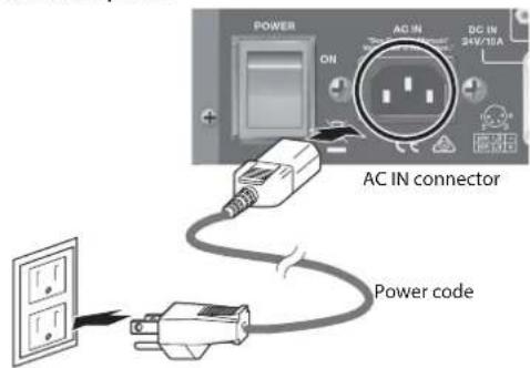
* The shape of the power cord's plug varies depending on the country.
natural_image
Isometric line drawing of a server rack unit with ventilation grilles and ventilation ducts (no text or labels)natural_image
Technical line drawing of a server rack frame with mounting holes and ventilation slots (no text or symbols)natural_image
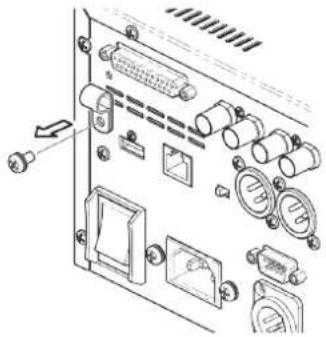
Technical line drawing of a mechanical assembly with mounting brackets and internal components (no text or symbols)Using the Power Cord Hook
- Remove the mounting screw indicated in the figure to detach the power cord hook.
natural_image
Technical diagram of an electronic device rear panel with ports and connectors (no text or labels)- Install the hook onto the power cord as shown in the figure, and secure in place using the screw removed in step 1.
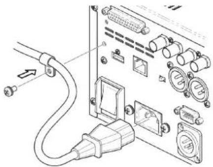
natural_image
Diagram of an electronic device showing cable, connector, and socket ports (no text or labels)Using an External Power Source
You can use an external DC source to power the V-1200HD.

NOTE
• To ensure the safe use of this product, use an external power source designed exclusively for use with data-processing equipment. Use an external power source that displays one of the following cautions, or a caution of like meaning.
- "FOR USE WITH IT EQUIPMENT ONLY"
- "FOR USE WITH INFORMATION TECHNOLOGYEQUIPMENT ONLY"
- Use an external power source that can supply at least 240W of current.
- Make sure that the wiring of the external power source you want to connect matches the external power connector on the V-1200HD. Connecting an external power source that has different wiring might cause malfunction.
- Be sure to supply DC power within the range of 22V to 26V. Using a voltage that is out of range might cause malfunction in the external power source or the V-1200HD.
Using an AC power outlet and an external power source at the same time is also possible. If either power source fails to supply sufficient current, operation automatically switches to the other. When using an external power source, be sure to refer to the owner's manual for the power source.
Turning the Power On and Off
* Before turning the unit on/off, always be sure to turn the volume down. Even with the volume turned down, you might hear some sound when switching the unit on/off. However, this is normal and does not indicate a malfunction.
Turning the Power On
* Once everything is properly connected (p. 21), be sure to follow the procedure below to turn on their power. If you turn on equipment in the wrong order, you risk causing malfunction or equipment failure.
-
Make sure all devices are turned off.
-
Turn on the [POWER] (main power) switch on the rear panel of the V-1200HD.
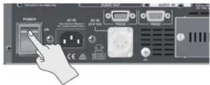
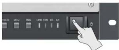
- Press the power button on the V-1200HD's front panel to turn on the power.
* This unit is equipped with a protection circuit. A brief interval (a few seconds) after turning the unit on is required before it will operate normally.
- Turn on the power to the source devices.
Turn on the power to the source devices (such as video cameras) connected to the V-1200HD.
- Turn on the power to the output devices.
Turn on the power to the output devices (such as monitors and projectors) connected to the V-1200HD.
Turning the Power Off
-
Power off the output devices first, and then power off the source devices.
-
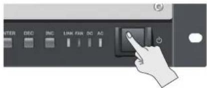
Press the power button on the V-1200HD's front panel to turn off the power.
* If you need to turn off the power completely, first turn off the unit, then unplug the power cord from the power outlet. Refer to "To completely turn off power to the unit, pull out the plug from the outlet" (p. 4).
* When turning off the power to the V-1200HD, first remove the USB flash drive from the USB port before you turn off the power. If the power is turned off while a flash drive remains connected to the V-1200HD, the V-1200HD might fail to start correctly at the next powerup.
natural_image
Technical line drawing of a mechanical or electronic component with no visible text, numbers, or symbols.natural_image
Line drawing of an electrical panel with plug, switches, and wiring (no text or symbols)• "FOR USE WITH IT EQUIPMENT ONLY"
• "FOR USE WITH INFORMATION TECHNOLOGYEQUIPMENT ONLY"
Installing an Expansion Interface (Option)
Optional XI-series expansion interfaces can be installed in the V-1200HD's expansion slots, enabling you to increase the available inputs and outputs.
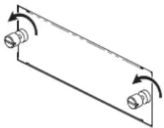
- Turn off the power to the V-1200HD and unplug the power cord from the power outlet.
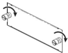
- Loosen the mounting screws (2) indicated in the figure and detach the expansion slot panel.
natural_image
Pure mechanical diagram showing two springs in a rectangular frame with rotational arrows (no text or symbols)- Insert the expansion interface.
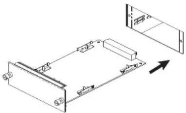
natural_image
Technical line drawing of a mechanical assembly with no visible text or symbols* To avoid the risk of damage to internal components that can be caused by static electricity, please carefully observe the following whenever you handle the expansion interface.
- Before you touch the expansion interface, always first grasp a metal object (such as a water pipe), so you are sure that any static electricity you might have been carrying has been discharged
- When handling the expansion interface, grasp it only by the panel or the expansion interface's edges. Avoid touching any of the electronic components or connectors.
- Save the bag in which the expansion interface was originally shipped, and put the board back into it whenever you need to store or transport it.
- Secure the expansion interface using the screws (2) specified in the figure.
natural_image
Pure diagram of a rectangular plate with two springs and rotational arrows indicating motion (no text or symbols)- Before installing the expansion interface, you must first always turn off the unit and unplug its power cord.
- Install only the specified expansion interface. Remove only the specified screws.
- Do not touch any of the printed circuit pathways or connection terminals.
- Never use excessive force when installing an expansion interface. If it doesn't fit properly on the first attempt, remove the expansion interface and try again.
- When the expansion interface installation is complete, doublecheck your work.
- Always turn the unit off and unplug the power cord before attempting installation of the expansion interface.
- Install only the specified expansion interface. Remove only the specified screws.
- When restarting the V-1200HD with an expansion interface installed, wait several seconds before you turn on the power.
Memo
- For information on the various settings for using expansion interfaces, refer to the "V-1200HDR/V-1200HD RCS Remote Control Guide" (PDF) available for download from the Roland website.

https://proav.roland.com/manuals/
- For detailed information about expansion interfaces, refer to the Roland website.
https://proav.roland.com/global/support/
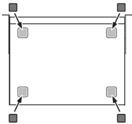
Attaching the Rubber Feet
Attach the included rubber feet as required, such as using the V-1200HD without mounting it in a rack.
Peel off the double-sided tape from the rubber feet and affix them at the locations shown in the figure.
* When turning the unit upside down, handle it carefully and do not drop it.
natural_image
Pure geometric diagram with four square nodes and arrows, no text or symbols presentnatural_image
Pure mechanical diagram showing a rectangular frame with two cylindrical components and rotational arrows indicating motion (no text or symbols)natural_image
Technical line drawing of a mechanical assembly with mounting brackets and a directional arrow (no text or symbols)natural_image
Pure diagram of a rectangular plate with two cylindrical connectors and curved arrows indicating rotation (no text or symbols)natural_image
Pure geometric diagram with four squares and arrows, no text or symbols presentFront Panel

| Number Name Description Page | |||
| 1 | USB port | This is a USB port exclusively for connecting a USB flash drive. Connect a USB flash drive to save/recall V-1200HD settings and import still images. * For information on importing still images, refer to the "V-1200HDR/V-1200HD RCS Remote Control Guide" (PDF) available for download at the Roland website. | p. 30 |
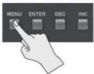
| 2 | [MENU] button | This displays the menu screen. The menu screen is shown on the monitor connected to the HDMI OUT MULTI-VIEW 2 connector. | p. 26 |
| [ENTER] button This confirms menu items and applies changes made to parameter values. p. 26 | |||
| [DEC] button | Use this to move between items and change parametera values on the menu screen. Pressing this makes the parametera value smaller. | p. 26 | |
| [INC] button | Use this to move between items and change parametera values on the menu screen. Pressing this makes the parametera value larger. | p. 26 | |
| 3 | LINK indicator | This lights up when a connection is established with the V-1200HDR dedicated controller (optional) or V-1200HD RCS remote-control software. | — |
| FAN indicator This flashes when the cooling fan experiences a problem and stops turning. — | |||
| DC indicator | This lights up when DC power is supplied from an external power unit connected to the rear panel. | — | |
| AC indicator | This lights up when AC power is supplied to the V-1200HD's internal power supply circuit. | — | |
| 4 | Power button | This turns the power to the V-1200HD on and off. * This is enabled only when the rear-panel [POWER] (main power) switch is set to "ON." | p. 12 |
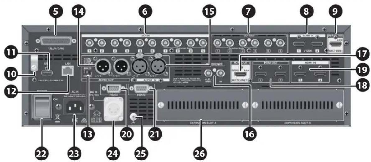
Rear Panel
(*1) For details about the multi-view screen, refer to the "V-1200HDR/V-1200HD RCS Remote Control Guide" (PDF) available for download from the Roland website.
| Number | Name Description Page | ||
| 5 | TALLY/GPIO connector | Connect devices provided with a tally-light feature and devices equipped with control-signal input/output functions here. | p. 28 |
| 6 | SDI IN connectors | These are connectors for inputting SDI signals. Use them with source devices equipped with SDI output connectors, such as 3G-SDI, HD-SDI, and SD-SDI devices. | p. 23 |
| 7 | SDI OUT connectors | These are connectors for outputting SDI signals. Use them with video devices equipped with SDI input connectors. | p. 25 |
| 8 | HDMI IN 1, 2 connectors | These are connectors for inputting HDMI signals. Use them with video cameras and other source devices equipped with HDMI output connectors. Input video formats that are compatible with the specified processing formats.* Copyright-protected (HDCP) video cannot be input. | p. 23 |
| 9 | HDMI OUT MULTI-VIEW 1 connector | Here you connect an HDMI monitor for multi-view display of the input/output list.Video selected from among the following is displayed on up to a 16-way split screen. (*1)SDI IN 1–10HDMI IN 1, 2EXP IN 1, 2 (input video from an optional expansion interface)SDI OUT1–6STILL1, 2 (still images imported from a USB flash drive)EXP OUT 1, 2 (output video sent to optional expansion interfaces)* Connect a monitor that supports 1080/60p HDMI input. | p. 25 |
| 10 | Power Cord Hook | You can use this power cord hook to prevent the power cord from being accidentally disconnected. | p. 12 |
| 11 | USB port | This is a USB connector for future feature expansion.* This port is not active in the initial release of the V-1200HD. | — |
| 12 | LAN port | Use this port to connect an optional V-1200HDR dedicated controller, or a computer on which the V-1200HD RCS remote-control software is installed. | p. 27 |
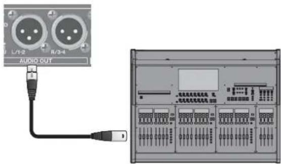
| 13 | Audio selector switch | This switches the input/output mode of the AUDIO IN and AUDIO OUT connectors. | p. 22 |
| 14 | AUDIO OUT connectors | These are connectors for outputting audio signals. Connect them to recording equipment, amplifiers, powered speakers, and other devices that receive audio. | p. 25 |
| 15 | AUDIO IN connectors | These are connectors for inputting audio signals. Use them with CD players and other audio source devices. | p. 24 |
| 16 | REFERENCE IN connector OUT/THRU connector | These are connectors for input and output of sync signals. | p. 24 |
| 17 | HDMI OUT MULTI-VIEW 2 connector | Here you can connect a monitor to display input/output lists and menu screens.The selected video is displayed on a four-way split screen. (*1)* Connect a monitor that supports copyright protection (HDCP).* Connect a monitor that supports 1080/60p HDMI input. | p. 25p. 26 |
| 18 | HDMI OUT 1, 2 connectors | These HDMI connectors output the video mixed on the V-1200HD. Use them with displays and other devices equipped with HDMI input connectors.Video from the 4:4:4 processing section is output. | p. 25 |
| 19 | HDMI IN 3, 4 connectors | These are connectors for inputting HDMI signals. Use them with computers and other source devices equipped with HDMI output connectors. Using the V-1200HD's built-in scalers, you can input a large number of video formats.These support HDCP signal input. (*2) | p. 23 |
| 20 | RS-232 connector | This is for connecting a remote-control device (such as an RS-232-compatible computer) for operating the V-1200HD remotely. | p. 28 |
| 21 | RS-422 connector | This connector allows you to connect to a VISCA-compatible camera and operate it remotely from the V-1200HD. | p. 29 |
| 22 | [POWER] (main power) switch | This turns the main power on and off. After the main power is turned on here, use the power button on the front panel to turn the V-1200HD on and off for everyday operation. | p. 12 |
| 23 | AC IN connector This is for connecting the included power cord. p. 10 | ||
| 24 | DC IN connector This is for connecting an external power supply. p. 12 | ||
| 25 | Ground terminal This terminal is used to connect the V-1200HD to an electrical ground. p. 22 | ||
| 26 | Expansion slots A, B | These are slots for installing optionally available Xi-series expansion interfaces. | p. 14 |
(*2) Settings must be made on the V-1200HD when inputting copyright-protected (HDCP) video. For details, refer to "About Copyright Protection (HDCP)" (p. 20).
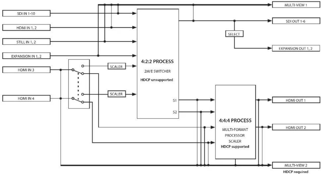
The V-1200HD comprises a 4:2:2 processing section that supports video formats such as 1080i, and a 4:4:4 processing section that supports XGA and other computer formats.
With the 4:2:2 section, you can select 2M/E, 1M/E, and other switcher configurations, and use keyers, picture-in-picture, and other forms of composition.
The 4:4:4 section lets you perform processing of high-quality computer video with no loss in image quality, and provides multi-format support using scalers. You can also input HDCP-protected video and produce screen-spanning and two-screen video.
The V-1200HD is configured so that output from the 4:2:2 processing section is input to the 4:4:4 processing section, enabling productions of greater complexity.
flowchart
graph TD
    A["SDI IN 1-10"] --> B["4:2:2 PROCESS"]
    C["HDMI IN 1,2"] --> B
    D["STILL IN 1,2"] --> B
    E["EXPANSION IN 1,2"] --> B
    F["HDMI IN 3"] --> G["4:4:4 PROCESS"]
    H["HDMI IN 4"] --> G
    B --> I["2M/E SWITCHER HDCP unsupported"]
    G --> J["MULTI-FORMAT PROCESSOR SCALER HDCP supported"]
    I --> K["S1"]
    I --> L["S2"]
    J --> M["HDMI OUT 1"]
    J --> N["HDMI OUT 2"]
    J --> O["MULTI-FORMAT PROCESSED"]
    P["SELECT"] --> Q["4:2:2 PROCESS"]
    P --> R["4:4:4 PROCESS"]
    Q --> S["MULTI-VIEW 1"]
    Q --> T["MULTI-VIEW 2"]
    Q --> U["SDI OUT 1-6"]
    Q --> V["EXPANSION OUT 1,2"]
    W["SDI VIEW 1"] --> X["MULTI-VIEW 1"]
    W --> Y["MULTI-VIEW 2"]
    Z["HDMI OUT 1"] --> AA["MULTI-FORMAT PROCESSED"]
    Z --> AB["MULTI-VIEW 2"]
    AC["HDMI OUT 2"] --> AD["MULTI-VIEW 2"]
    AC --> AE["MULTI-VIEW required"]
* The number of usable layers and AUXes varies according to the M/E settings and selections. You use a V-1200HDR or V-1200HD RCS remote-control software to make the settings. For details, refer to the "V-1200HDR/V-1200HD RCS Remote Control Guide" (PDF) available for download at the Roland website.
* EXPANSION IN 1 and 2 and EXPANSION OUT 1 and 2 become usable when an optional expansion interface is installed (p. 14).
* For HDMI IN 3 and HDMI IN 4, you can select whether the connection destination is the 4:2:2 process section or the 4:4:4 process section. You use the V-1200HDR or V-1200HD RCS remote-control software to make the setting for the connection destination. For details, refer to the "V-1200HDR/V-1200HD RCS Remote Control Guide" (PDF) available for download at the Roland website.
About Processing Formats
For both the 4:2:2 process and the 4:4:4 process, you first select the processing format. Choose the desired format from the options available for each section.
Memo
You use the V-1200HDR or V-1200HD RCS remote-control software to set the processing format. For details, refer to the "V-1200HDR/V-1200HD RCS Remote Control Guide" (PDF) available for download at the Roland website.
4:2:2 Process
With the 4:2:2 process, you can input video that is compatible with the selected process format.
Video processed by the 4:2:2 section is output in the same format as the selected format. For example, if the format is set to 1080/59.94i, the format of video you can input is 1080/59.94i, and the output video format is also 1080/59.94i.
Video processed by the 4:2:2 section is output externally to SDI OUT 1 through 6 and EXPANSION OUT 1 and 2, and also internally to the 4:4:4 processing section.
| Selectable 4:2:2 processing formats | 1080/59.94i, 1080/50i, 1080/59.94p, 1080/50p* compliant with SMPTE 274M* The 4:2:2 process format is set to “1080/59.94i” by default. |
* When HDMI IN 3 or 4 is connected to the 4:2:2 process section, video in formats other than the specified 4:2:2 processing format can be input via HDMI IN 3 or 4. For details, refer to "About Processing Formats" (p. 19).
* The possible number of compositions such as chroma key and picture-in-picture differs according to the selected format and the mode setting. For details, refer to the "V-1200HDR/V-1200HD RCS Remote Control Guide" (PDF) available for download at the Roland website.
4:4:4 Process
The 4:4:4 process receives the signal from the output of the 4:2:2 process section, as well as external video arriving at HDMI IN 3 and 4. Video passes through an internal scaler before input, which means that you can input video in a format other than the selected 4:4:4 processing format. (*1) After processing, video from the 4:4:4 section is output via HDMI OUT 1 and 2 in the specified format.
| Selectable 4:4:4 processing formats | 480/59.94i, 576/50i, 480/59.94p, 576/50p, 720/59.94p, 720/50p, 1080/59.94i, 1080/50i, 1080/59.94p, 1080/50p, 1024x768/60Hz (*2), 1280x720/60Hz (*2), 1280x800/60Hz (*2), 1366x768/60Hz (*2), 1280x1024/60Hz (*2), 1400x1050/60Hz (*2), 1600x1200/60Hz, 1920x1080/60Hz, 1920x1200/60Hz* The 4:4:4 process format is set to "1920 x1080/60Hz" by default. |
(*1) You can input video in all formats listed above.
(*2) When the frame rate is set to 50 Hz, the output refresh rate is 75 Hz.
About HDMI IN 3 and 4
You can select whether the connection destination for HDMI IN 3 and 4 is the 4:2:2 process section or the 4:4:4 process section. By passing video through the internal scaler, you can input video in a format other than the processing format specified for the respective section. For instance, even when the 4:2:2 section is set to a processing format of 1080/59.94i, you can input video at 1920x1200/60 Hz to HDMI IN 3 and 4. The formats you can input via HDMI IN 3 and 4 are as shown below.
| Formats supported by HDMI IN 3 and 4 | 480/59.94i, 576/50i, 480/59.94p, 576/50p, 720/59.94p, 720/50p, 1080/59.94i, 1080/50i, 1080/59.94p, 1080/50p, 1024x768/60Hz (*3), 1280x720/60Hz (*3), 1280x800/60Hz (*3), 1366x768/60Hz (*3), 1280x1024/60Hz (*3), 1400x1050/60Hz (*3), 1600x1200/60Hz, 1920x1080/60Hz, 1920x1200/60Hz(*3) When the frame rate is set to 50 Hz, the output refresh rate is 75 Hz. |
Memo
You use the V-1200HDR or remote-control software to make the connection-destination setting for HDMI 3 and 4. For details, refer to the "V-1200HDR/V-1200HD RCS Remote Control Guide" (PDF) available for download at the Roland website. https://proav.roland.com/manuals/

About Copyright Protection (HDCP)
The V-1200HD's 4:4:4 section supports copyright protection (HDCP).
When all of the following conditions are satisfied, you can input an HDCP signal into the V-1200HD and output HDCP-applied video to the monitor.
•The HDCP signal is input via either HDMI IN 3 or HDMI IN 4.
• HDMI IN 3 or 4 is connected to the 4:4:4 section. (*4)
• HDCP for the 4:4:4 section is turned on. (*4)
- An HDCP-compatible HDMI monitor is connected to either HDMI OUT 1 or HDMI OUT 2.
(*4) To make the settings, use either the V-1200HDR or remote-control software. For details, refer to the "V-1200HDR/V-1200HD RCS Remote Control Guide" (PDF) available for download at the Roland website.
Memo
By default, HDCP for the 4:4:4 section is set to "off."
NOTE
- The 4:2:2 section does not support HDCP. HDCP signals cannot be input via HDMI IN 1 or 2.
Also, HDCP signals cannot be input via HDMI IN 3 or 4 when they are connected to the 4:2:2 section. - When HDCP for the 4:4:4 process is turned on, video sent from HDMI OUT 1 and 2 is output with HDCP applied. When HDCP is turned on, connect HDCP-compatible monitors to HDMI OUT 1 and 2.
- Connect an HDCP-compatible monitor to HDMI OUT MULTI-VIEW 2.
Roland website
https://proav.roland.com/global/support/
You connect external equipment as shown in this chapter. For information on specific connection methods, refer to page 23 and after.
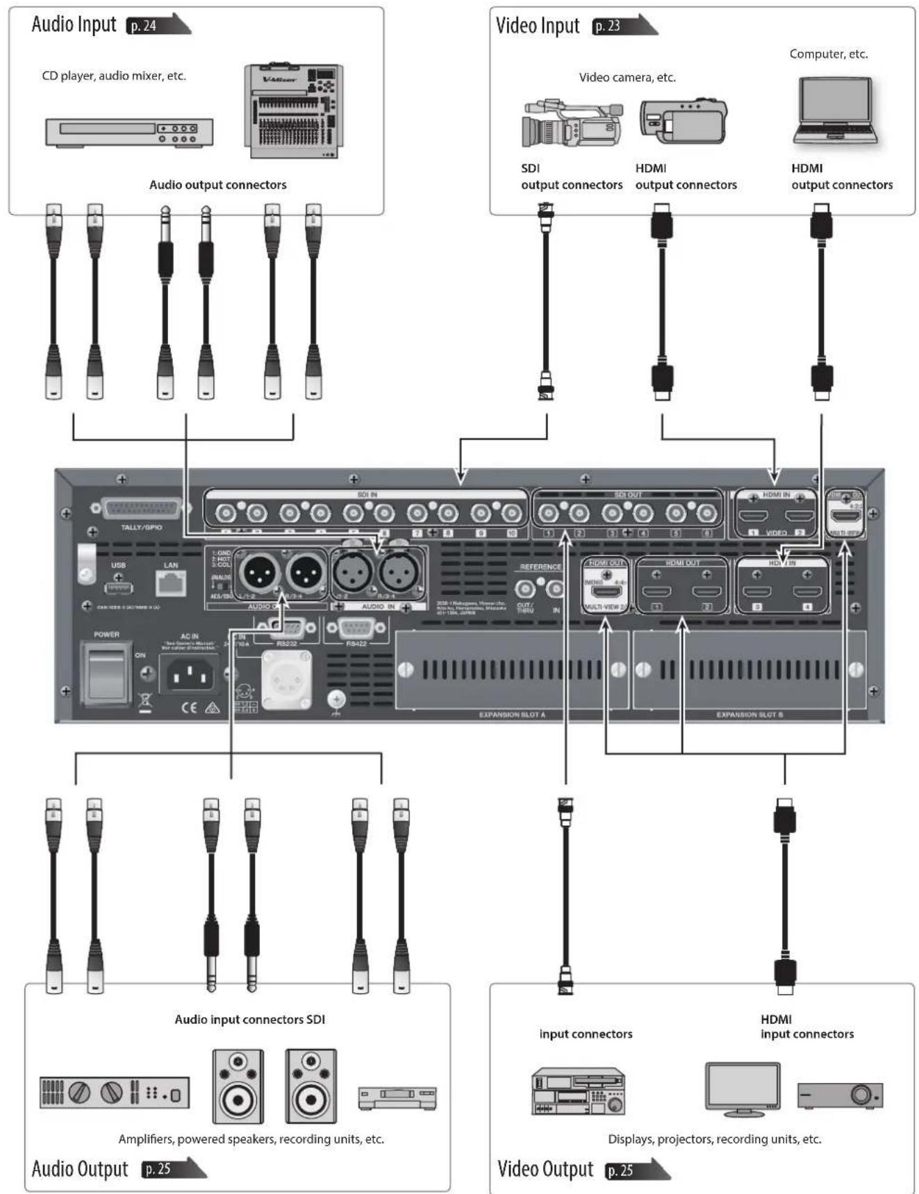
* To prevent malfunction and equipment failure, always turn down the volume, and turn off all the units before making any connections.
* Provide cable and adapter plugs to match the connector configuration on the equipment you're using.
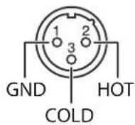
* This instrument is equipped with balanced (XLR) type jacks. Wiring diagrams for these jacks are shown below. Make connections after first checking the wiring diagrams of other equipment you intend to connect.
AUDIO IN connector
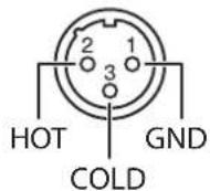
AUDIO OUT connector
About the Ground Terminal
Depending on the circumstances of a particular setup, you may experience a discomforting sensation, or perceive that the surface feels gritty to the touch when you touch this device, microphones connected to it, or the metal portions of other objects. This is due to an infinitesimal electrical charge, which is absolutely harmless. However, if you are concerned about this, connect the ground terminal (see figure) with an external ground. When the unit is grounded, a slight hum may occur, depending on the particulars of your installation. If you are unsure of the connection method, contact the nearest Roland Service Center, or an authorized Roland distributor, as listed on the "Information" page. Unsuitable places for connection

Unsuitable places for connection
•Water pipes (may result in shock or electrocution)
•Gas pipes (may result in fire or explosion)
- Telephone-line ground or lightning rod (may be dangerous in the event of lightning)
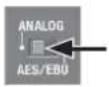
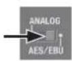
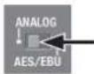
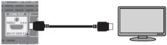
About the Audio Selector Switch
The V-1200HD's audio input/output connectors support either analog or digital (AES/EBU) signals. Use the audio selector switch to choose the signal type for your connected equipment.
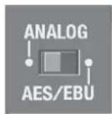
* The audio selector switch setting affects both input and output signals. For example, selecting "ANALOG" sets both the AUDIO IN and AUDIO OUT connectors to function as analog connectors.
Connecting Source Equipment
Connect your external devices to the respective input connectors for video and audio.
Connecting Video Source Equipment
Connect video source devices to the SDI IN and HDMI IN connectors.
Memo
The formats that can be input to the respective connectors vary according to the specified processing format. For details, refer to "About Processing Formats" (p. 19).
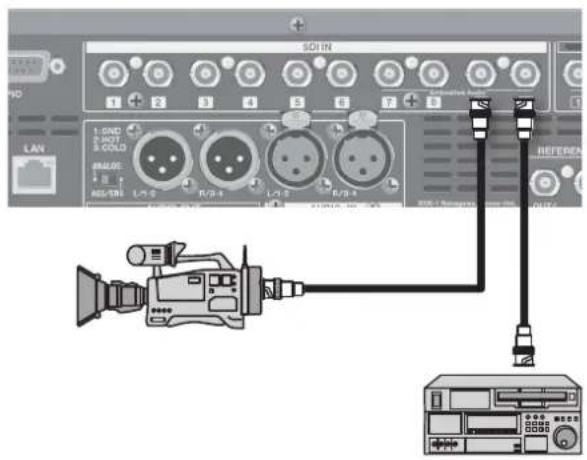
Making SDI Connections
Connect video cameras, video decks, and other SDI devices to SDI IN connectors 1 through 10.
Memo
- Input video in formats that are compatible with the specified process formats. For details, refer to "About Processing Formats" (p. 19).
- SDI IN 7–10 each support embedded 16 channels of audio input.
Making HDMI Connections
Connect video cameras, computers, and other devices equipped with HDMI outputs to the HDMI IN connectors.
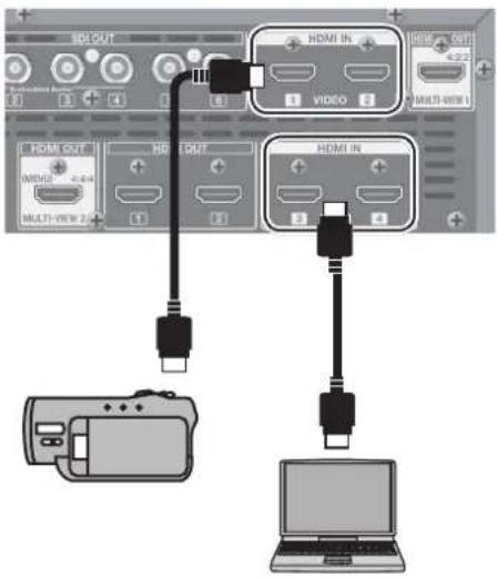
| HDMI IN 1, 2 | •Input video in formats that are compatible with the specified process formats.For details, refer to “About Processing Formats” (p. 19).•Copyright-protected (HDCP) video cannot be input. |
| HDMI IN 3, 4 | •Using the built-in scalers, you can input a large number of video formats.For information on the formats you can input, refer to “About HDMI IN 3 and 4” (p. 20).•These support HDCP signal input. |
NOTE
Settings must be made on the V-1200HD when inputting copyright-protected (HDCP) video. For details, refer to "About Copyright Protection (HDCP)" (p. 20).
Memo
When connecting a device equipped with a DVI output, use a DVI-to-HDMI conversion cable and make the connection to an HDMI IN connector.
Connecting Audio Source Equipment
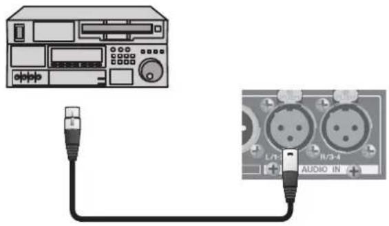
Making an Analog Connection
Connect the analog output of the audio source device to an AUDIO IN connector.
natural_image
Diagram showing audio connection between a CD-ROM and two connected audio pins (no text or symbols present)Set the audio selector switch to [ANALOG].
NOTE
The audio selector switch affects both input and output. For details, refer to "About the Audio Selector Switch" (p. 22).
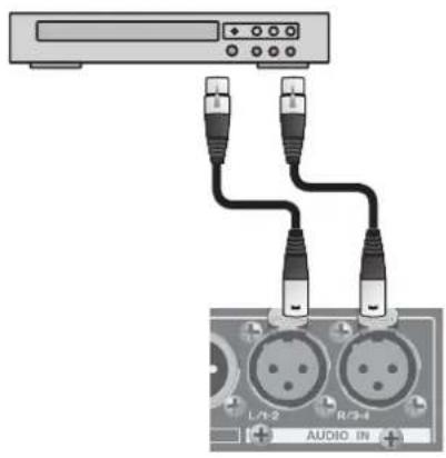
Making a Digital Connection
Connect the digital (AES/EBU) output of the audio source device to an AUDIO IN connector.
* Use an AES/EBU-compliant cable.
The V-1200HD supports the AES3 standard (24 bits, 48 kHz, two channels).
Set the audio selector switch to [AES/EBU].
NOTE
The audio selector switch affects both input and output. For details, refer to "About the Audio Selector Switch" (p. 22).
Connecting a Reference
You can connect a source device for synchronizing.
* You can also output a reference signal via the OUT/THRU connector. For details, refer to the "V-1200HDR/V-1200HD RCS Remote Control Guide" (PDF) available for download at the Roland website.
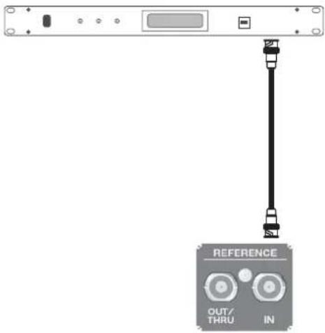
The V-1200HD supports the following external clocks.
- Black burst (frame synchronization)
• Bi-level synchronization, tri-level synchronization
Memo
The clock source is set to "INTERNAL" by default. To use an external clock, this setting must be changed using a V-1200HDR unit or V-1200HD RCS. For details, refer to the "V-1200HDR/V-1200HD RCS Remote Control Guide" (PDF) available for download at the Roland website.
https://proav.roland.com/manuals/

Connecting Output Equipment
Connecting Video Output Equipment
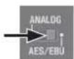
Making HDMI Connections
Connect television monitors and other equipment provided with HDMI input to the respective HDMI OUT connectors.
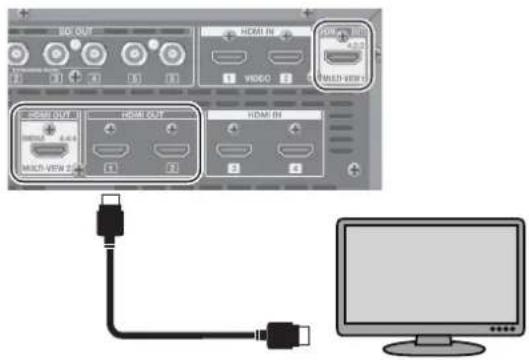
| MULTI-VIEW 1 | Video selected from among the following is displayed on up to a 16-way split screen. (*1)SDI IN 1-10HDMI IN 1, 2EXP IN 1, 2 (input video from an optional expansion interface)SDI OUT1-6STILL1, 2 (still images imported from a USB flash drive)* Connect a monitor that supports 1080/60p HDMI input. |
| MULTI-VIEW 2 | Here you connect a monitor for displaying input/output lists and menu screens.The selected video is displayed on a four-way split screen. (*1)* Connect an HDCP-compatible monitor.* Connect a monitor that supports 1080/60p HDMI input. |
| HDMI OUT 1, 2 | These output video from the V-1200HD's 4:4:4 process. The output video is output in the specified 4:4:4 processing format.For information on 4:4:4 formats, refer to "4:4:4 Process" (p. 20). |
(*1) For details about the multi-view screen, refer to the "V-1200HDR/V-1200HD RCS Remote Control Guide" (PDF) available for download from the Roland website.
https://proav.roland.com/manuals/

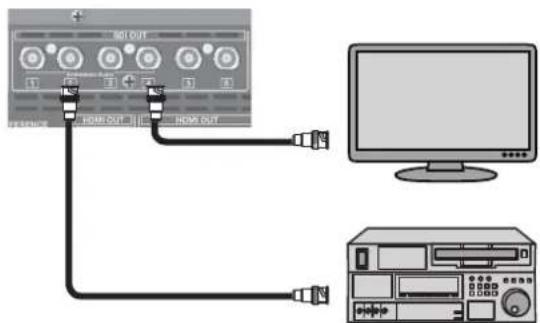
Making SDI Connections
Connect monitors, video decks (for recording), and other devices equipped with SDI inputs to the SDI OUT connectors. Video is output in the specified 4:2:2 processing format. For information on 4:2:2 formats, refer to "4:2:2 Process" (p. 19).
Connecting Audio Output Equipment
Making an Analog Connection
Connect the analog inputs of amplifiers, powered speakers, and recording equipment to the AUDIO OUT connectors.
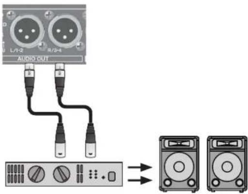
Set the audio selector switch to [ANALOG].
* The nominal output level of the V-1200HD is +4 dBu. Connect equipment that accommodates this nominal output level.
NOTE
The audio selector switch affects both input and output. For details, refer to "About the Audio Selector Switch" (p. 22).
Making a Digital Connection
Connect audio output equipment that has digital (AES/EBU) input to the AUDIO OUT connectors.
* Use an AES/EBU-compliant cable. The V-1200HD supports the AES3 standard (24 bits, 48 kHz, two channels).
Set the audio selector switch to [AES/EBU].
NOTE
The audio selector switch affects both input and output. For details, refer to "About the Audio Selector Switch" (p. 22).
You can display menus on a multi-view monitor connected to the V-1200HD and use them to make various settings.
Using the Menus
Menu operations follow the procedure described below.
1. Connect a monitor to the HDMI OUT MULTI-VIEW 2 connector.
The setup menu appears on the monitor connected to HDMI OUT MULTI-VIEW 2.
2. Display the menu.
Press the [MENU] button to display the menu.
| Setup Menu | |
| System | ENTER |
| Backup | ENTER |
| Restore | ENTER |
| Format | ENTER |
| Factory Reset | ENTER |
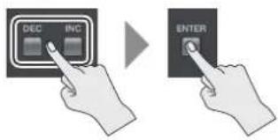
3. Select the target menu.
Use the [DEC] and [INC] buttons to select the desired menu item, then press the [ENTER] button.
The items belonging to the selected menu are displayed.
* For information on where to look for explanations of the items and to find out about operation procedures, refer to "Menu Organization" below.
4. Exit the menu.
When the item operations end, press the [MENU] button several times to quit the menu.
Menu Organization
The V-1200HD's menus are organized as shown below.
| Menu Item Description | Section to see | |
| System Displays the program version information. "Checking the Version Information" (p. 30) | ||
| Backup | This saves a settings file on a USB flash drive or deletes a settings file saved on a USB flash drive. | "Saving a New Settings File (Save As)" (p. 30)"Saving Settings by Overwriting" (p. 30)"Deleting Settings" (p. 30) |
| Restore Loads a settings file saved on a USB flash drive. "Recalling Settings" (p. 30) | ||
| Format Formats a USB flash drive. "Formatting a USB Flash Drive" (p. 30) | ||
| Factory Reset Returns the unit's settings to their factory defaults. | "Returning Settings to the Factory-Default State (Factory Reset)" (p. 30) | |
You can connect a remote-control device and use it to operate the V-1200HD.
Using a V-1200HDR Dedicated Controller
You can connect a V-1200HDR dedicated controller (optional) to the LAN port and use it to operate the V-1200HD remotely.
Memo
For more information on how to use the V-1200HDR, refer to the "V-1200HDR Owner's Manual" and "V-1200HDR/V-1200HD RCS Reference Manual" (PDF) available for download at the Roland website.
- Connect the V-1200HDR to the LAN port on the V-1200HD.
- Turn on the power to the V-1200HD.
- Turn on the power to the V-1200HDR.
- The LINK indicator on the V-1200HD lights up when communication with the V-1200HDR is established.
* Communication is not established if the V-1200HD and the V-1200HDR are connected after the power has been turned on. If the connection has been made while in this state, communication can be established by resetting the power on just the V-1200HDR.
* Using an Ethernet switching hub, you can connect V-1200HDR units and computers installed with V-1200HD RCS (up to two devices in total) to the V-1200HD. When connecting multiple V-1200HDR units or computers, each controller must be assigned a different "CONTROL SURFACE ID" setting. For information on how to make this setting, refer to the "V-1200HDR/V-1200HD RCS Remote Control Guide" (PDF) available for download at the Roland website.
* Use a Category 5e or higher shielded Ethernet cable for connection. Crossover cables and straight cables are both supported.
* Connect no devices other than the V-1200HD, V-1200HDR units, and computers installed with V-1200HD RCS to the same network.
Using V-1200HD RCS Dedicated Software
You can connect a computer on which the V-1200HD RCS dedicated control software is installed up and use it to operate the V-1200HD remotely.
Memo
For more information on how to use the V-1200HD RCS, refer to the "V-1200HD Owner's Manual" and "V-1200HDR/V-1200HD RCS Reference Manual" (PDF) available for download at the Roland website.
- Start the computer on which the V-1200HD RCS is installed.
- Make the network settings on the computer.
* For information on how to make the network settings, refer to the "V-1200HDR/V-1200HD RCS Remote Control Guide" (PDF) available for download at the Roland website.
- Connect the computer to the LAN port on the V-1200HD.
- Turn on the power to the V-1200HD.
- Start V-1200HD RCS.
- The LINK indicator on the V-1200HD lights up when communication with the computer is established.
* If you're using a computer running Windows, then if the Ethernet cable is disconnected and reconnected after communication between the V-1200HD and V-1200HD RCS has been established, communication might fail to be reestablished. If this happens, you can establish communication while the devices are connected by going to the computer's network settings and setting Local Area Connection to "Disable" and then again to "Enable."
* Using an Ethernet switching hub, you can connect V-1200HDR units and computers installed with V-1200HD RCS (up to two devices in total) to the V-1200HD.
When connecting multiple V-1200HDR units or computers, each controller must be assigned a different "CONTROL SURFACE ID" setting. For information on how to make this setting, refer to the "V-1200HDR/V-1200HD RCS Remote Control Guide" (PDF) available for download at the Roland website.
* Use a Category 5e or higher shielded Ethernet cable for connection. Crossover cables and straight cables are both supported.
* Connect no devices other than the V-1200HD, V-1200HDR units, and computers installed with V-1200HD RCS to the same network.
Using the RS-232 Connector
You can use the RS-232 connector to operate the V-1200HD from a computer, touch panel, or other external control device.
Memo
For more information on how to operate the V-1200HD via the RS-232 connector, refer to the "V-1200HDR/V-1200HD RCS Remote Control Guide" (PDF) available for download at the Roland website.
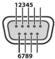
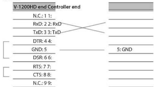
D-Sub 9-pin (male)
| Pin number | Signal name |
| 1 N.C. | |
| 2 RxD | |
| 3 TxD | |
| 4 DTR | |
| 5 GND | |
| 6 DSR | |
| 7 RTS | |
| 8 CTS | |
| 9 N.C. |
| Transmission method | Start-stop synchronization(asynchronous mode), full-duplex |
| Communication speed (baud rate) | 9600 bps/38400 bps |
| Parity None | |
| Data length 8 bit | |
| Stop-bit length 1 bit | |
| Code set ASCII | |
| Flow control XON/XOFF |
Cable Wiring Diagram
Wire the three lines of RxD, TxD, and GND as shown in the figure below.
* The connections between 4 and 6 and between 7 and 8 are inside the V-1200HD.
* When connecting to a controlling device (such as an RS-232-compatible computer), use a crossover cable.
Using the TALLY/GPIO Connector
You can use the TALLY/GPIO connector to control the V-1200HD from an external device.
The TALLY/GPIO connector accommodates input and output of control signals, and also tally-signal output.
* For detailed information on the TALLY/GPIO connector, refer to "About the TALLY/GPIO Connector" (p. 29).
Roland website
https://proav.roland.com/global/support/
Operating a VISCA-Compatible Video Camera by Remote Control
You can connect a VISCA-compatible video camera to the RS-422 connector and operate the camera remotely from the V-1200HD.
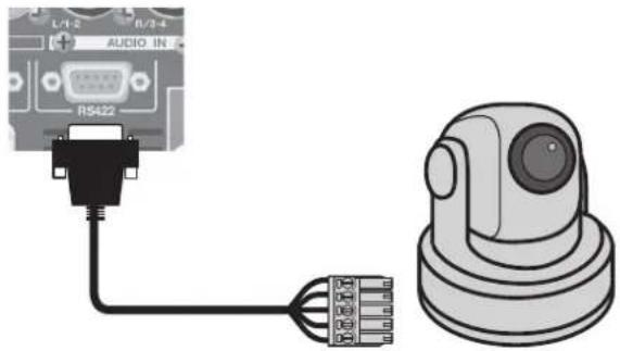
For more information on how to do this, refer to the "V-1200HDR/V-1200HD RCS Remote Control Guide" (PDF) available for download at the Roland website.
https://proav.roland.com/manuals/

RS-422 Connector Specifications
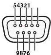
D-Sub 9-pin (female)
| Pin No. Signal name | |
| 1 GND | |
| 2 TxD+ | |
| 3 RxD- | |
| 4 GND | |
| 5 | NC |
| 6 GND | |
| 7 TxD- | |
| 8 RxD+ | |
| 9 GND | |
| Transmission method | Start-stop synchronization (asynchronous mode), full-duplex |
| Communication speed (baud rate) | 9600 bps/38400 bps |
| Parity None | |
| Data length 8 bits | |
| Stop-bit length 1 bit | |
| Flow control None |
About the TALLY/GPIO Connector
The V-1200HD is equipped with a D-Sub 25-pin TALLY/GPIO connector. In addition to tally input/output functions, this provides functionality for control signal input and output, and you can use it to transmit and receive control signals between the unit and an external device.
TALLY/GPIO Connector Specifications
•Tally/control output connector specifications
Maximum input: 12 V/200 mA
Open-collector type
- Control input connector specifications
Trigger method: No-voltage contact (make-contact)
triggeringContact capacity: DC 24 V 0.1 A or higher
Input method: Photocoupler
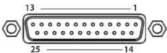
D-Sub 25-pin (female)
* By default, the following functions are assigned to the V-1200HD's TALLY/GPIO connector.
| Pin number | Connector name | Function | Default |
| 1 | OUTPUT 1/GPO 1 | Tally output/control output | SDI 1 PGM |
| 2 | OUTPUT 2/GPO 2 | SDI 1 PST | |
| 3 | OUTPUT 3/GPO 3 | SDI 2 PGM | |
| 4 | OUTPUT 4/GPO 4 | SDI 2 PST | |
| 5 | OUTPUT 5/GPO 5 | SDI 3 PGM | |
| 6 | OUTPUT 6/GPO 6 | SDI 3 PST | |
| 7 | OUTPUT 7/GPO 7 | SDI 4 PGM | |
| 8 | OUTPUT 8/GPO 8 | SDI 4 PST | |
| 9 | OUTPUT 9/GPO 9 | SDI 5 PGM | |
| 10 | OUTPUT 10/GPO 10 | SDI 5 PST | |
| 11 | OUTPUT 11/GPO 11 | SDI 6 PGM | |
| 12 | OUTPUT 12/GPO 12 | SDI 6 PST | |
| 13 | OUTPUT 13/GPO 13 | SDI 7 PGM | |
| 14 | OUTPUT 14/GPO 14 | SDI 7 PST | |
| 15 | OUTPUT 15/GPO 15 | SDI 8 PGM | |
| 16 | OUTPUT 16/GPO 16 | SDI 8 PST | |
| 17 | — | GND | COM(GND) |
| 18 | INPUT 1 | Control input | N/A |
| 19 | INPUT 2 | N/A | |
| 20 | INPUT 3 | N/A | |
| 21 | INPUT 4 | N/A | |
| 22 | INPUT 5 | N/A | |
| 23 | INPUT 6 | N/A | |
| 24 | INPUT 7 | N/A | |
| 25 | INPUT 8 | N/A |
Memo
You can use the V-1200HDR or V-1200HD RCS to change the function assignments. For information on how to make the settings, refer to the "V-1200HDR/V-1200HD RCS Remote Control Guide" (PDF) available for download at the Roland website.
https://proav.roland.com/manuals/

Saving/Recalling Settings
This saves the following settings together in a single file to a USB flash drive connected to the USB port. You can then recall the saved file from the USB flash drive to the V-1200HD for use when needed.
● Settings Saved on the USB Flash Drive
The settings saved in MEMORY 1 through 8 in V-1200HD RCS or on the V-1200HDR are saved to the USB flash drive.
* The current settings are not saved.
Saving a New Settings File (Save As)
-
Press the [MENU] button → select "Backup" → "Save As," then press the [ENTER] button.
-
Specify the file name, select "SAVE," then press the [ENTER] button.
The extension of the file name is [V12].
- The message "Push ENTER to execute." appears. To execute the operation, press the [ENTER] button. (If you want to cancel the operation, press the [MENU] button.)
The new settings file is saved on the USB flash drive.
Saving Settings by Overwriting
-
Press the [MENU] button → select "Backup" → "Save" then press the [ENTER] button.
-
Select the file to overwrite, then press the [ENTER] button.
-
The message "Push ENTER to execute." appears. To execute the operation, press the [ENTER] button. (If you want to cancel the operation, press the [MENU] button.)
The settings are saved on the USB flash drive, overwriting the older file.
Deleting Settings
-
Press the [MENU] button → select "Backup" → "Delete" then press the [ENTER] button.
-
Select the file to delete, then press the [ENTER] button.
-
The message "Push ENTER to execute." appears. To execute the operation, press the [ENTER] button. (If you want to cancel the operation, press the [MENU] button.)
The settings are deleted from the USB flash drive.
Recalling Settings
This recalls the settings for MEMORY 1 through 8 saved on a USB flash drive. Recalling the settings overwrites any values currently in MEMORY 1 through 8.
* The current settings remain when the settings for MEMORY 1 through 8 are recalled.
-
Press the [MENU] button → "Restore" then press the [ENTER] button.
-
Select the file to load, then press the [ENTER] button.
-
The message "Push ENTER to execute." appears. To execute the operation, press the [ENTER] button. (If you want to cancel the operation, press the [MENU] button.)
The settings are recalled.
Checking the Version Information
This displays the program version information for the V-1200HD itself (MAIN) and for expansion interfaces (EXP A and EXP B) connected at expansion slots A and B.
- Press the [MENU] button and select "System," then press the [ENTER] button.
The program version information is displayed.
* When no expansion interfaces are inserted into expansion slots A and B, no version information is displayed at "EXP A" and "EXP B."
Formatting a USB Flash Drive
To use a USB flash drive with the V-1200HD, it must first be formatted with the unit.
NOTE
- The V-1200HD does not recognize unformatted USB flash drives. - Performing formatting causes all data already saved on the USB flash drive to be deleted. If the flash drive contains necessary data, back it up onto a computer or elsewhere before formatting the drive.
-
Connect the USB flash drive to the USB port on the front panel.
-
Press the [MENU] button and select "Format," then press the [ENTER] button.
-
The message "Push ENTER to execute." appears. To execute the operation, press the [ENTER] button. (If you want to cancel the operation, press the [MENU] button.)
Formatting of the USB flash drive is carried out.
NOTE
- When turning off the power to the V-1200HD, first remove the USB flash drive from the USB port before you turn off the power. If the power is turned off while a flash drive remains connected to the V-1200HD, the V-1200HD might fail to start correctly at the next powerup.
- Connect the flash drive to the USB port located on the front panel. (No operation takes place if the drive is connected to the USB port on the rear panel.)
- Carefully insert the USB flash drive all the way in—until it is firmly in place.
- Never turn off the power or disconnect the USB flash drives when the access lamp of USB flash drives are lit or blinking
- After connecting the USB flash drive, a short wait may be required until reading and writing data is possible.
Returning Settings to the Factory-Default State (Factory Reset)
This returns values that have been set to their factory defaults. If operation that differs from what is described in the owner's manual occurs even when the steps are followed correctly, try performing a factory reset.
NOTE
Executing a factory reset causes all settings made up to then to be lost.
-
Press the [MENU] button and select "Factory Reset," then press the [ENTER] button.
-
The message "Push ENTER to execute." appears. To execute the operation, press the [ENTER] button. (If you want to cancel the operation, press the [MENU] button.)
A factory reset is executed.
Symptom Cause Corrective action Page
| Is copyright-protected (HDCP) video being input? | Copyright-protected (HDCP) video signals can be input when they meet all of the following conditions. | ||
| •Input is via the HDMI IN 3 or 4 connector. | p. 20 | ||
| •The HDCP setting is set to ON. | |||
| •The 4:4:4 process is speci ed as the connection destination for HDMI IN 3 or 4. | |||
| No picture is input. | Do the settings match the video format of the input? | Set the process format of the V-1200HD to match the video format of the input to the 4:2:2 process. | p. 19 |
| For example, if the 4:2:2 process format on the V-1200HD is set to 1080/59.94i, the only video format that can be input to the 4:2:2 process is 1080/59.94i. | |||
| You can input video formats other than the set process format to HDMI IN 3 and 4. For details, refer to “About HDMI IN 3 and 4” (p. 20). | |||
| Is copyright-protected (HDCP) video being output? Check whether an HDCP-compatible monitor is being used. — | |||
| No picture is output. | Does the output-destination device (HDMI monitor, etc.) support the output setting speci ed on the V-1200HD? | On the V-1200HD, video in the same format as the process format set for the respective process is output. | p. 19 |
| For instance, if the process format for the 4:4:4 process is set to 1080/59.94p and video is output from the HDMI OUT 1 connector, video output is possible if the output-destination device (HDMI monitor, etc.) supports a 1080/59.94p signal. | |||
| Are the patchbay settings correct? | Use an optional V-1200HDR unit or remote-control software to change the patchbay settings. (*1) | — | |
| Use an optional V-1200HDR unit or remote-control software to change the settings for the color space. (*1) | — | ||
| Colors are incorrect. | Does the color space of the video being input or output match the color space for the processing being done by the unit? | Depending on the device, the color space might be interlinked with the selection of DVI or HDMI or the selected format. In such cases, changing the color space on the input or output device might bring about improvement for the problem. | — |
| HDMI output shown on a display has its periphery cut off. | Are the display settings compatible? | In the case of an HDMI signal, overscanning might be performed automatically, depending on the display. Change the display's settings. | — |
| Remote control from a V-1200HDR unit or V-1200HD RCS is not possible. | Is the LINK indicator on the front panel dark? | Connect the V-1200HDR or V-1200HD RCS to the V-1200HD correctly. | p. 27 |
| Is an external power source whose voltage is outside the range of DC 22 V to 26 V being used? | Stop using the external power source and use the included AC power cord to supply from a power outlet. | p. 12 | |
| The body of the V-1200HD is extremely hot. | Has the cooling fan stopped? | Immediately stop use and contact a Roland Service Center. — | |
| Is the FAN indicator on the front panel ashing? | |||
| Was the USB ash drive formatted on the unit? | When you're using a USB ash drive for the 1st time, be sure to format it on the unit. | p. 30 | |
| A USB flash drive cannot be read. | Was a non-Roland USB ash drive used? | Operation of non-Roland USB ash drives cannot be assured. Operation has been tested for commonly available USB ash drives, but operation with all USB ash drives is not assured. Depending on the manufacturer and type of the USB ash drive, correct operation may not be possible. | — |
(*1) For detailed information on operation, refer to the "V-1200HDR/V-1200HD RCS Remote Control Guide" (PDF) available for download at the Roland website.
Main Specifications
Roland V-1200HD: Multi-format Video Switcher
Video
| Processing 4:4:4 (Y/Pb/Pr, RGB), 10 bits/4:2:2 (Y/Pb/Pr), 10 bits | |||
| Input Connectors | 3G/HD-SDI BNC type x 10 * Conforms to SMPTE 424M (SMPTE 425M-AB), 292M | ||
| HDMI type A x 2 (HDMI INPUT 1–2) * HDCP Not supported | |||
| HDMI type A x 2 (HDMI INPUT 3–4) * HDCP Supported, Multi-format Supported | |||
| Output Connectors | 3G/HD-SDI BNC type x 6 * Conforms to SMPTE 424M (SMPTE 425M-AB), 292M | ||
| HDMI type A x 2 (HDMI OUTPUT 1–2) * HDCP Supported | |||
| HDMI | type A x 2 (HDMI OUTPUT MULTI-VIEW 1) * HDCP Not required, 1080/60p(HDMI OUTPUT MULTI-VIEW 2) * HDCP Required, 1080/60p | ||
| Formats | SDI 1080/59.94i, 1080/50i, 1080/59.94p, 1080/50p, * Conforms to SMPTE 274M | ||
| HDMI | 480/59.94i, 576/50i, 480/59.94p, 576/50p, 720/59.94p, 720/50p, 1080/59.94i, 1080/50i, 1080/59.94p, 1080/50p,1024x768/60 (*1), 1280x720/60 (*1), 1280x800/60 (*1), 1366x768/60 (*1), 1280x1024/60 (*1), 1400x1050/60 (*1),1600x1200/60, 1920x1080/60, 1920x1200/60 RB* Conforms to CEA-861-E,VESA DMT Version 1.0 Revision 11* The output format of HDMI1–2 is always the same.* Frame rate is 59.94 Hz (NTSC) or 50 Hz (PAL).* MULTI-VIEW 1–2 output is 1080/60p always.(*1) Output refresh rate is 75 Hz when frame rate is set to 50 Hz. | ||
| Effects (4:2:2 Processing)* These effects depends on M/E type. | M/E 1M/E, 1.5M/E, 2M/E (9 types) | AUX 2 | |
| Transition | Mix, NAM (*2), FAM (*2), Cut, Wipe(*2) PGM/PST only | Others | |
| Composition (Keyer) | 4 (PinP, Luminance Key, Chroma Key,External Key supported) | ||
| Effects (4:4:4 Processing)* These effects depends on M/E type. | M/E 1M/E, Matrix, Scaler | Composition (Keyer) | 1 (PinP, Luminance Key) |
| Input | 4 (4:2:2 Processing outputs x 2, HDMI INPUT 3,HDMI INPUT 4) | Others | |
| Transition Mix, Cut | |||
| Still Image | Inputs 2 | ||
| Internal Memory 16 | |||
| Maximum Size 192D x 1080 pixels | |||
| Format | Windows Bitmap File (.bmp) 24 bit per pixel, uncompressed, Portable Network Graphic File (.png)* Alpha channel supported. | ||
| Multiviewer | MULTI-VIEW 1 (4:2:2 Processing): 16/10 screens, Label, Tally * HDCP Not supported | ||
| MULTI-VIEW 2 (4:4:4 Processing): 4/10 screens, Label, Tally, OSD Setup Menu * HDCP Required | |||
Audio
| Processing Sampling Rate 24 bits/48 kHz | ||
| Input Connectors | 3G/HD-SDI: BNC type x 4 (Ch7-10), HDMI: type A x 4, AUDIO IN (XLR) L (1/2)/R (3/4) * Analog Audio or AES/EBU | |
| Output Connectors | 3G/HD-SDI: BNC type x 4 (Ch1-4), HDMI: type A x 4, AUDIO OUT (XLR) L (1/2)/R (3/4) * Analog Audio or AES/EBU | |
| Input Level and Impedance | AUDIO IN | +4 dBu (Maximum: +22 dBu, 15 k ohms) |
| Output Level and Impedance | AUDIO OUT | +4 dBu (Maximum: +22 dBu, 600 ohms) |
| Formats | SDI Linear PCM, 24 bits, 48 kHz, 16ch * Conforms to SMPTE 299M | |
| HDMI Linear PCM, 24 bits, 48 kHz, 2ch | ||
| AES/EBU | Linear PCM, 24 bits, 48 kHz, 4ch | |
| Effects | Patchbay | 92 inputs x 92 outputs |
| Delay 16 ch | ||
| Mixer 16 ch (Channel Effects: 3-Band EQ, Delay/Master Effects: Mastering, 3-Band EQ, Reverb) | ||
Others
| Expansion Slot | Slot | 2 * The video a maximum of 2 inputs 2 outputs and the audio a maximum of 16 inputs 16 outputs can treat in 2 slots sum total. | ||
| Reference | Input | BNC type x 1 * Black Burst (Sync to frames), Bi-Level, Tri-Level | ||
| Output/Through BNC type x 1 * Black Burst (Sync to frames) | ||||
| External Connectors | RS-232 | DB-9 type (Male) x 1 * for Remote Control | ||
| RS-422 | DB-9 type (Female) x 1 * for VISCA Control | |||
| TALLY/GPIO | DB-25 type (Female) x 1 (Input: 8, Output/Tally: 16) | |||
| LAN RJ45 100BASE | TX (Connect to V-1200HDR or Computer (V-1200HD RCS)) | |||
| USB | A type x 2 (USB Memory/Use for future expansion) | |||
| Preset Memory | 8 * Last Memory Function | |||
| User Function | 32 * 16 buttons x 2 banks | |||
| Remote Camera Control | Connector | RS-422: DB-9 type (Female) x 1 | Operation Temperature | +0 to +40 degrees Celsius+32 to +104 degrees Fahrenheit |
| Protocol | VISCA | |||
| Remore Controller | V-1200HDR Control Surface * Sold separatelyV-1200HD RCS * Windows7 SP1 or later, Mac OS X | Dimensions | 482 (W) x 357 (D) x 133 (H) mm19 (W) x 14-1/16 (D) x 5-1/4 (H) inches* EIA-3U rack mount size | |
| Power Supply | AC 117 V, AC 220 V, AC 230 V, AC 240 V (50/60 Hz)DC 24 V (XLR-4-32 type)* Redundant Power Supply. | |||
| Weight | 9.0 kg19 lbs 14 oz | |||
| Power Consumption | 90 W/0.8 A (117V), 90 W/0.5 A (220V, 230V, 240V), 90 W/3.75 A (DC 24V)* When expansion slot is void. | Accessories | Power Cord, Rubber Feet,Owner's Manual | |
* 0 dBu = 0.775 Vrms
* This product is a Class A digital device under FCC part 15.
* In the interest of product improvement, the specifications and/or appearance of this unit are subject to change without prior notice.
Dimensions
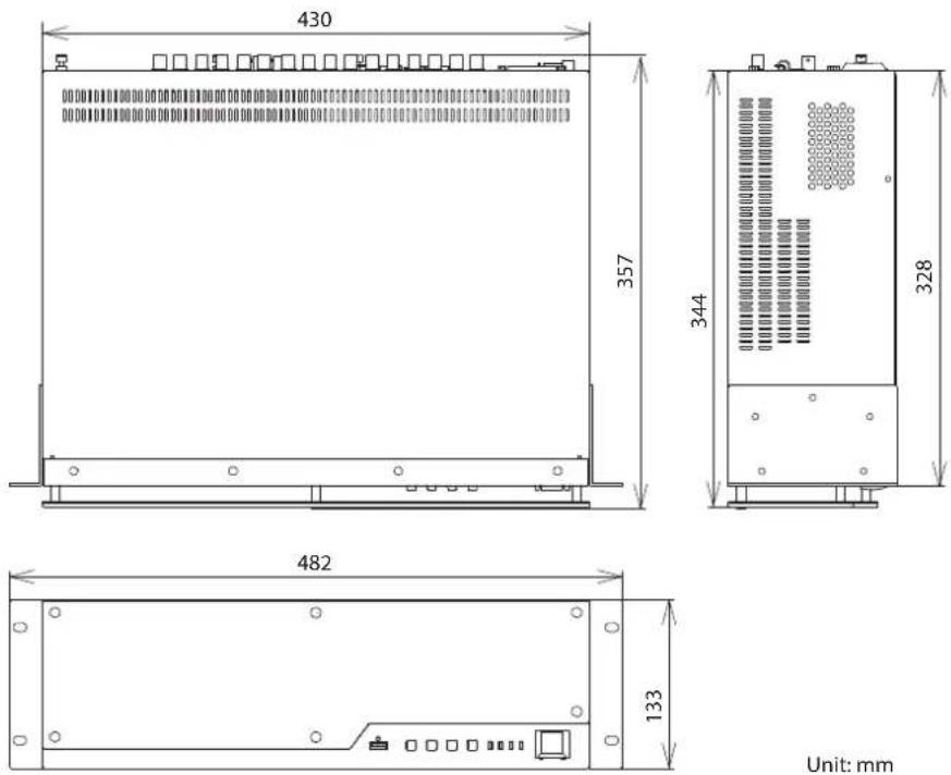
Unit: mm
Block Diagram
Video Block
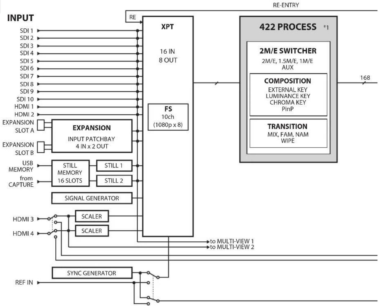
flowchart
graph TD
    A["INPUT"] --> B["XPT"]
    B --> C["16 IN 8 OUT"]
    B --> D["FS 10ch (1080p x 8)"]
    D --> E["422 PROCESS *1"]
    E --> F["2M/E SWITCHER"]
    E --> G["COMPOSITION"]
    E --> H["TRANSITION"]
    B --> I["EXPANSION INPUT PATCHBAY 4 IN x 2 OUT"]
    I --> J["EXPANSION SLOT A"]
    I --> K["EXPANSION SLOT B"]
    J --> L["USB MEMORY"]
    J --> M["from CAPTURE"]
    K --> N["STILL MEMORY 16 SLOTS"]
    K --> O["STILL 1"]
    K --> P["STILL 2"]
    L --> Q["SIGNAL GENERATOR"]
    M --> Q
    N --> Q
    O --> Q
    P --> Q
    Q --> R["SCALER"]
    Q --> S["SCALER"]
    R --> T["to MULTI-VIEW 1"]
    S --> U["to MULTI-VIEW 2"]
    V["REF IN"] --> W["SYNC GENERATOR"]
    W --> X["168"]
    style A fill:#f9f,stroke:#333
    style E fill:#ccf,stroke:#333
Audio Block
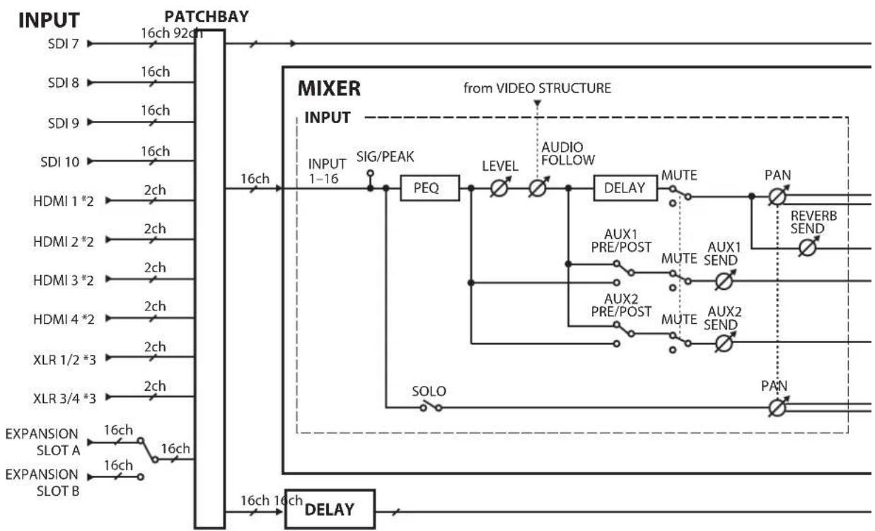
flowchart
graph LR
    A["INPUT"] --> B["16ch 92ch"]
    B --> C["16ch"]
    C --> D["PACKBAY"]
    D --> E["MIXER INPUT"]
    E --> F["INPUT 1-16"]
    F --> G["SIG/PEAK"]
    G --> H["PEQ"]
    H --> I["LEVEL"]
    I --> J["AUDIO FOLLOW"]
    J --> K["DELAY"]
    K --> L["MUTE"]
    L --> M["PAN"]
    M --> N["REVERB SEND"]
    N --> O["AUX1 PRE/POST"]
    O --> P["MUTE"]
    P --> Q["AUX1 SEND"]
    Q --> R["AUX2 PRE/POST"]
    R --> S["MUTE"]
    S --> T["AUX2 SEND"]
    T --> U["SOLO"]
    U --> V["EXPANSION SLOT A"]
    U --> W["EXPANSION SLOT B"]
    V --> X["16ch 16ch"]
    W --> Y["16ch 16ch"]
    X --> Z["DELAY"]
    Y --> AA["DELAY"]
    Z --> AB["16ch 16ch"]
    AA --> AC["16ch 16ch"]
    AD["from VIDEO STRUCTURE"] -.-> E
*1: Varies according to M/E configuration.
*2: HDCP-applied audio cannot be input.
*3: When the audio selector switch is set to AES/EBU, 2 channels each of AES/EBU input and output are possible. When the switch is set to ANALOG, 1 channel each of input and output are possible.
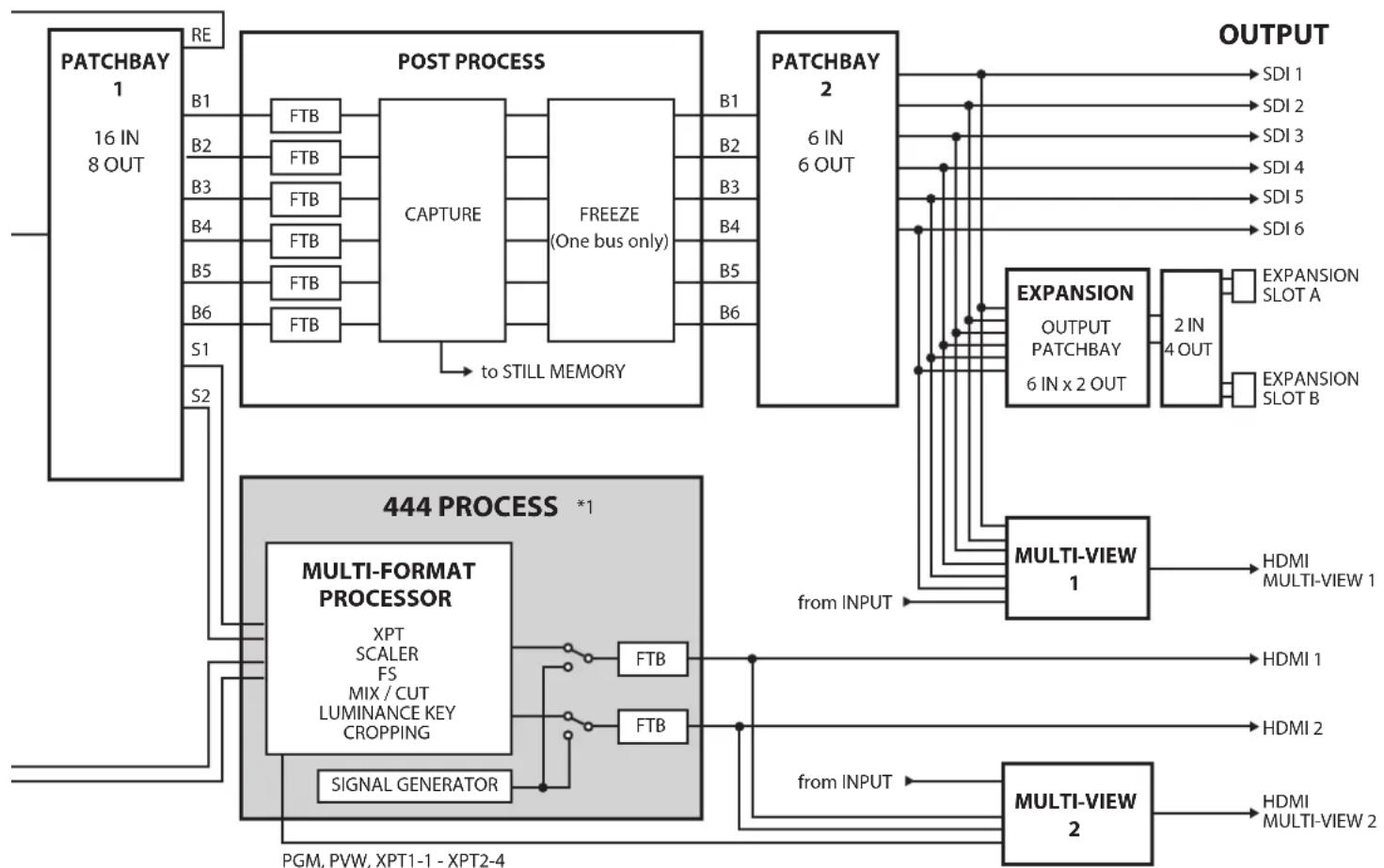
flowchart
graph TD
    A["PATCHBAY 1<br>16 IN<br>8 OUT"] -->|RE| B["POST PROCESS"]
    B --> C["CAPTURE"]
    C --> D["FREEZE<br>(One bus only)"]
    D --> E["to STILL MEMORY"]
    E --> F["3D/4D OUTPUT"]
    F --> G["EXPANSION OUTPUT PATCHBAY 6 IN x 2 OUT"]
    G --> H["2 IN 4 OUT"]
    H --> I["EXPANSION SLOT A"]
    H --> J["EXPANSION SLOT B"]
    K["444 PROCESS *1"] --> L["MULTI-FORMAT PROCESSOR<br>XPT SCALER FS MIX / CUT LUMINANCE KEY CROPPING"]
    L --> M["FTB"]
    L --> N["FTB"]
    L --> O["SIGNAL GENERATOR"]
    P["OUTPUT"] --> Q["SDI 1"]
    P --> R["SDI 2"]
    P --> S["SDI 3"]
    P --> T["SDI 4"]
    P --> U["SDI 5"]
    P --> V["SDI 6"]
    W["MultiVIEW 1"] --> X["HDMI MULTI-VIEW 1"]
    X --> Y["HDMI 1"]
    X --> Z["HDMI 2"]
    AA["MultiVIEW 2"] --> AB["HDMI MULTI-VIEW 2"]
    AB --> AC["HDMI MULTI-VIEW 2"]
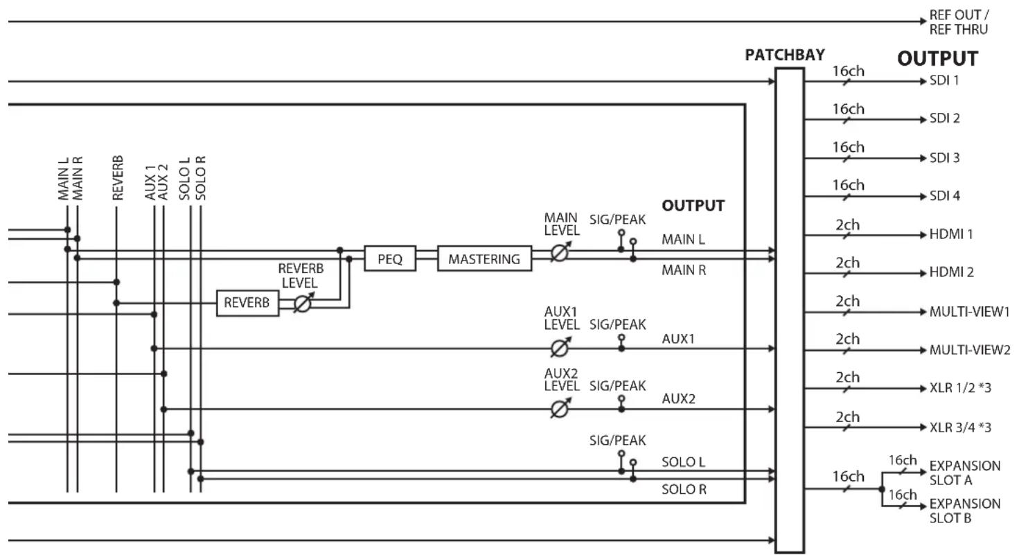
flowchart
graph LR
    A["MAIN L"] --> B["REVERB"]
    B --> C["AUX 1"]
    C --> D["AUX 2"]
    D --> E["SOLO L"]
    E --> F["SOLOR"]
    F --> G["REVERB LEVEL"]
    G --> H["PEQ"]
    H --> I["MASTERING"]
    I --> J["MAIN LEVEL"]
    I --> K["SIG/PEAK"]
    K --> L["OUTPUT MAIN L"]
    L --> M["MAN R"]
    M --> N["PATCHBAY"]
    N --> O["OUTPUT SDI 1"]
    N --> P["OUTPUT SDI 2"]
    N --> Q["OUTPUT SDI 3"]
    N --> R["OUTPUT SDI 4"]
    N --> S["OUTPUT HDMI 1"]
    N --> T["OUTPUT HDMI 2"]
    N --> U["OUTPUT MULTI-VIEW1"]
    N --> V["OUTPUT MULTI-VIEW2"]
    N --> W["OUTPUT XLR 1/2 *3"]
    N --> X["OUTPUT XLR 3/4 *3"]
    N --> Y["OUTPUT EXPANSION SLOT A"]
    N --> Z["OUTPUT EXPANSION SLOT B"]
Memo
FEDERAL COMMUNICATIONS COMMISSION RADIO FREQUENCY INTERFERENCE STATEMENT
This equipment has been tested and found to comply with the limits for a Class A digital device, pursuant to Part 15 of the FCC Rules. These limits are designed to provide reasonable protection against harmful interference when the equipment is operated in a commercial environment. This equipment generates, uses, and can radiate radio frequency energy and, if not installed and used in accordance with the instruction manual, may cause harmful interference to radio communications. Operation of this equipment in a residential area is likely to cause harmful interference in which case the user will be required to correct the interference at his own expense.
This device complies with Part 15 of the FCC Rules. Operation is subject to the following two conditions:
(1) this device may not cause harmful interference, and
(2) this device must accept any interference received, including interference that may cause undesired operation.
To assure continued FCC emission limit compliance, use only shielded interface cables when connecting to other device.
Any unauthorized changes or modifications not expressly approved by the party responsible for compliance could void the user's authority to operate the equipment.
For Canada
CAN ICES-3 (A)/NMB-3 (A)
For Korea
사용자 안내문
Manufacturer: Roland Corporation
2036-1 Nakagawa, Hosoe-cho, Kita-ku, Hamamatsu, Shizuoka 431-1304, JAPAN
Importer: Roland Corporation
ENA 23 Zone 1 nr. 1620 Klaus-Michael Kuehnelaan 13, 2440 Geel, BELGIUM
Warning: Operation of this equipment in a residential environment could cause radio interference.

For the U.K.
Manufacturer: Roland Corporation
2036-1 Nakagawa, Hosoe-cho, Kita-ku, Hamamatsu, Shizuoka 431-1304, JAPAN
Importer: Roland Europe Group Limited
Hive 2, 1530 Arlington Business Park, Theale, Reading, Berkshire. RG7 4SA United Kingdom

Warning: Operation of this equipment in a residential environment could cause radio interference.
For EU Countries

This product is intended for use in the following Electromagnetic environments:
E4: controlled EMC environment,
ex. broadcasting studio which are specified in EN55103-1 and EN55103-2.
For EU Countries

UK This symbol indicates that in EU countries, this product must be collected separately from household waste, as defined in each region. Products bearing this symbol must not be discarded together with household waste.
Roland Service Centers and Distributors
When you need repair service, access this URL and find your nearest Roland Service Center or authorized Roland distributor in your country.
https://roland.cm/proav_service