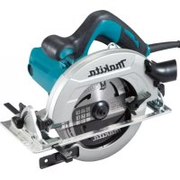
USER MANUAL HS7611K MAKITA
natural_image
Technical line drawing of a mechanical power saw assembly (no text or symbols)


natural_image
Line drawing of a person using a power tool on a workbench, no text or symbols present

natural_image
Illustration showing two hands operating a cutting machine and inspecting a mechanical component with a prohibition symbol (no text or symbols present)

natural_image
Technical line drawing of a mechanical device mounted on a table, labeled Fig.2 (no text or symbols on the diagram itself)
natural_image
Line drawing of a manual machine with a circular symbol above it, no text or symbols present
natural_image
Line drawing of a mechanical device on a table with a prohibition symbol above (no text or labels)

natural_image
Illustration of hands operating a cutting machine with a no-smoking symbol above (no text or labels)

natural_image
Technical line drawing of a mechanical device with labeled component '1', no readable text or symbols beyond label

natural_image
Technical line drawing of a mechanical assembly with labeled component (no text or symbols beyond label)



natural_image
Technical diagram of a mechanical assembly with labeled parts, showing internal components and motion arrows (no text or symbols)




natural_image
Technical line drawing of a car seatbelt assembly with labeled component (no text or symbols beyond label)


natural_image
Line drawing of hands operating a cutting tool on a workbench (no text or symbols)



natural_image
Technical line drawing of a mechanical spring assembly with labeled dimension (no text or symbols beyond label)

SPECIFICATIONS
| Model: HS7611 | |
| Blade diameter 185 - 190 mm | |
| Max. Cutting depth at 0° 63 - 65 mm | |
|
|
| No load speed 5,500 min | -1 |
| Overall length 311 mm | |
| Net weight 3.9 kg | |
| Safety class | ☐/II |
- Due to our continuing program of research and development, the specifications herein are subject to change without notice.
• Specifications may differ from country to country.
• Weight according to EPTA-Procedure 01/2014
Intended use
The tool is intended for performing lengthways and crossways straight cuts and miter cuts with angles in wood while in firm contact with the workpiece. With appropriate Makita genuine saw blades, other materials can also be sawed.
Power supply
The tool should be connected only to a power supply of the same voltage as indicated on the nameplate, and can only be operated on single-phase AC supply. They are double-insulated and can, therefore, also be used from sockets without earth wire.
For public low-voltage distribution systems of between 220 V and 250 V
Switching operations of electric apparatus cause voltage fluctuations. The operation of this device under unfavorable mains conditions can have adverse effects to the operation of other equipment. With a mains impedance equal or less than 0.33 Ohms it can be presumed that there will be no negative effects. The mains socket used for this device must be protected with a fuse or protective circuit breaker having slow tripping characteristics.
Noise
The typical A-weighted noise level determined according to EN62841-2-5:
Sound pressure level ( LpA ): 98 dB (A)
Sound power level ( LWA ): 106 dB (A)
Uncertainty (K) : 3 dB (A)
NOTE: The declared noise emission value(s) has been measured in accordance with a standard test method and may be used for comparing one tool with another.
NOTE: The declared noise emission value(s) may also be used in a preliminary assessment of exposure.
WARNING: Wear ear protection.
WARNING: The noise emission during actual use of the power tool can differ from the declared value(s) depending on the ways in which the tool is used especially what kind of workpiece is processed.
⚠ WARNING: Be sure to identify safety measures to protect the operator that are based on an estimation of exposure in the actual conditions of use (taking account of all parts of the operating cycle such as the times when the tool is switched off and when it is running idle in addition to the trigger time).
Vibration
The vibration total value (tri-axial vector sum) determined according to EN62841-2-5:
Work mode: cutting wood
Vibration emission (ah,w): 2.5 m/s 2 or less
Uncertainty (K) : 1.5 m/s 2
NOTE: The declared vibration total value(s) has been measured in accordance with a standard test method and may be used for comparing one tool with another.
NOTE: The declared vibration total value(s) may also be used in a preliminary assessment of exposure.
⚠ WARNING: The vibration emission during actual use of the power tool can differ from the declared value(s) depending on the ways in which the tool is used especially what kind of workpiece is processed.
⚠ WARNING: Be sure to identify safety measures to protect the operator that are based on an estimation of exposure in the actual conditions of use (taking account of all parts of the operating cycle such as the times when the tool is switched off and when it is running idle in addition to the trigger time).
For European countries only
The Declarations of conformity are included in Annex A to this instruction manual.
SAFETY WARNINGS
⚠ WARNING Read all safety warnings, instructions, illustrations and specifications provided with this power tool. Failure to follow all instructions listed below may result in electric shock, fire and/or serious injury.
Save all warnings and instructions for future reference.
The term "power tool" in the warnings refers to your mains-operated (corded) power tool or battery-operated (cordless) power tool.
Circular saw safety warnings
Cutting procedures
- ⚠️DANGER: Keep hands away from cutting area and the blade. Keep your second hand on auxiliary handle, or motor housing. If both hands are holding the saw, they cannot be cut by the blade.
- Do not reach underneath the workpiece. The guard cannot protect you from the blade below the workpiece.
- Adjust the cutting depth to the thickness of the workpiece. Less than a full tooth of the blade teeth should be visible below the workpiece.
- Never hold the workpiece in your hands or across your leg while cutting. Secure the workpiece to a stable platform. It is important to support the work properly to minimise body exposure, blade binding, or loss of control.
▶ Fig.1
- Hold the power tool by insulated gripping surfaces, when performing an operation where the cutting tool may contact hidden wiring or its own cord. Contact with a "live" wire will also make exposed metal parts of the power tool "live"
and could give the operator an electric shock.
- When ripping, always use a rip fence or straight edge guide. This improves the accuracy of cut and reduces the chance of blade binding.
- Always use blades with correct size and shape (diamond versus round) of arbour holes.
Blades that do not match the mounting hardware of the saw will run off-centre, causing loss of control.
- Never use damaged or incorrect blade washers or bolt. The blade washers and bolt were specially designed for your saw, for optimum performance and safety of operation.
— kickback is a sudden reaction to a pinched, jammed or misaligned saw blade, causing an uncontrolled saw to lift up and out of the workpiece toward the operator;
— when the blade is pinched or jammed tightly by the kerf closing down, the blade stalls and the motor reaction drives the unit rapidly back toward the operator;
— if the blade becomes twisted or misaligned in the cut, the teeth at the back edge of the blade can dig into the top surface of the wood causing the blade to climb out of the kerf and jump back toward the operator.
Kickback is the result of saw misuse and/or incorrect operating procedures or conditions and can be avoided by taking proper precautions as given below.
- Maintain a firm grip with both hands on the saw and position your arms to resist kickback forces. Position your body to either side of the blade, but not in line with the blade. Kickback could cause the saw to jump backwards, but kickback forces can be controlled by the operator, if proper precautions are taken.
- When blade is binding, or when interrupting a cut for any reason, release the trigger and hold the saw motionless in the material until the blade comes to a complete stop. Never attempt to remove the saw from the work or pull the saw backward while the blade is in motion or kickback may occur. Investigate and take corrective actions to eliminate the cause of blade binding.
- When restarting a saw in the workpiece, centre the saw blade in the kerf so that the saw teeth are not engaged into the material. If a saw blade binds, it may walk up or kickback from the workpiece as the saw is restarted.
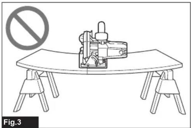
- Support large panels to minimise the risk of blade pinching and kickback. Large panels tend to sag under their own weight. Supports must be placed under the panel on both sides, near the line of cut and near the edge of the panel.
▶ Fig.2
▶ Fig.3
- Do not use dull or damaged blades.
Unsharpened or improperly set blades produce narrow kerf causing excessive friction, blade binding and kickback.
- Blade depth and bevel adjusting locking levers must be tight and secure before making the
cut. If blade adjustment shifts while cutting, it may cause binding and kickback.
- Use extra caution when sawing into existing walls or other blind areas. The protruding blade may cut objects that can cause kickback.
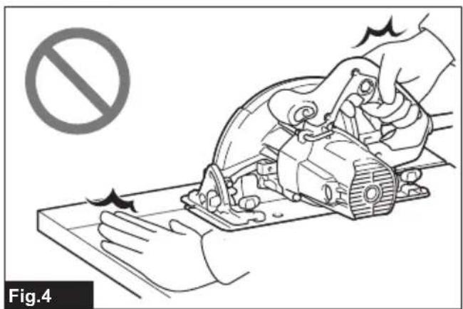
- ALWAYS hold the tool firmly with both hands. NEVER place your hand, leg or any part of your body under the tool base or behind the saw, especially when making cross-cuts. If kickback occurs, the saw could easily jump backwards over your hand, leading to serious personal injury.
▶ Fig.4
- Never force the saw. Push the saw forward at a speed so that the blade cuts without slowing. Forcing the saw can cause uneven cuts, loss of accuracy, and possible kickback.
Lower guard function
- Check the lower guard for proper closing before each use. Do not operate the saw if the lower guard does not move freely and close instantly. Never clamp or tie the lower guard into the open position. If the saw is accidentally dropped, the lower guard may be bent. Raise the lower guard with the retracting handle and make sure it moves freely and does not touch the blade or any other part, in all angles and depths of cut.
- Check the operation of the lower guard spring. If the guard and the spring are not operating properly, they must be serviced before use. Lower guard may operate sluggishly due to damaged parts, gummy deposits, or a build-up of debris.
- The lower guard may be retracted manually only for special cuts such as "plunge cuts" and "compound cuts". Raise the lower guard by the retracting handle and as soon as the blade enters the material, the lower guard must be released. For all other sawing, the lower guard should operate automatically.
- Always observe that the lower guard is covering the blade before placing the saw down on bench or floor. An unprotected, coasting blade will cause the saw to walk backwards, cutting whatever is in its path. Be aware of the time it takes for the blade to stop after switch is released.
- To check lower guard, open lower guard by hand, then release and watch guard closure. Also check to see that retracting handle does not touch tool housing. Leaving blade exposed is VERY DANGEROUS and can lead to serious personal injury.
Additional safety warnings
- Use extra caution when cutting damp wood, pressure treated lumber, or wood containing knots. Maintain smooth advancement of tool without decrease in blade speed to avoid overheating the blade tips.
- Do not attempt to remove cut material when blade is moving. Wait until blade stops before grasping cut material. Blades coast after turn off.
- Avoid cutting nails. Inspect for and remove all nails from lumber before cutting.
- Place the wider portion of the saw base on that part of the workpiece which is solidly
supported, not on the section that will fall off when the cut is made. If the workpiece is short or small, clamp it down. DO NOT TRY TO HOLD SHORT PIECES BY HAND!
▶ Fig.5
- Before setting the tool down after completing a cut, be sure that the guard has closed and the blade has come to a complete stop.
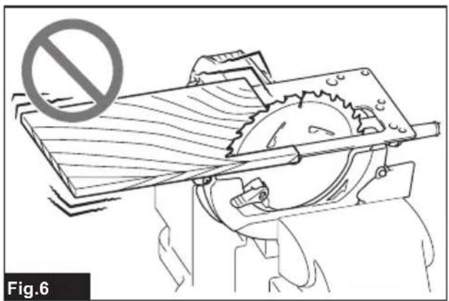
- Never attempt to saw with the circular saw held upside down in a vise. This is extremely dangerous and can lead to serious accidents.
▶ Fig.6
- Some material contains chemicals which may be toxic. Take caution to prevent dust inhalation and skin contact. Follow material supplier safety data.
- Do not stop the blades by lateral pressure on the saw blade.
- Do not use any abrasive wheels.
- Only use the saw blade with the diameter that is marked on the tool or specified in the manual. Use of an incorrectly sized blade may affect the proper guarding of the blade or guard operation which could result in serious personal injury.
- Keep blade sharp and clean. Gum and wood pitch hardened on blades slows saw and increases potential for kickback. Keep blade clean by first removing it from tool, then cleaning it with gum and pitch remover, hot water or kerosene. Never use gasoline.
- Wear a dust mask and hearing protection when use the tool.
- Always use the saw blade intended for cutting the material that you are going to cut.
- Only use the saw blades that are marked with a speed equal or higher than the speed marked on the tool.
- (For European countries only)
Always use the blade which conforms to EN847-1, if intended for wood and analogous materials.
- Place the tool and the parts on a flat and stable surface. Otherwise the tool or the parts may fall and cause an injury.
SAVE THESE INSTRUCTIONS.
⚠ WARNING: DO NOT let comfort or familiarity with product (gained from repeated use) replace strict adherence to safety rules for the subject product. MISUSE or failure to follow the safety rules stated in this instruction manual may cause serious personal injury.
FUNCTIONAL DESCRIPTION
CAUTION: Always be sure that the tool is switched off and unplugged before adjusting or checking function on the tool.
Adjusting depth of cut
⚠️CAUTION: After adjusting the depth of cut, always tighten the lever securely.
Loosen the lever on the depth guide and move the base up or down. At the desired depth of cut, secure the base by tightening the lever.
For cleaner, safer cuts, set cut depth so that no more than one blade tooth projects below workpiece. Using proper cut depth helps to reduce potential for dangerous KICKBACKS which can cause personal injury.
▶ Fig.7: 1. Depth gauge 2. Lever 3. Base
Bevel cutting
⚠️CAUTION: After adjusting the bevel angle, always tighten the clamping screws securely.
Loosen the front and rear clamping screws. Set for the desired angle ( 0irc - 45irc ) by tilting accordingly, then tighten the front and rear clamping screws securely.
▶ Fig.8: 1. Clamping screw
▶ Fig.9: 1. Clamping screw
Sighting
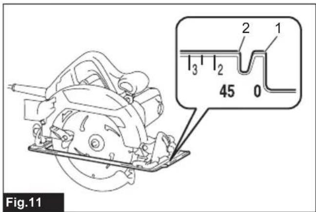
For straight cuts, align the 0irc position on the front of the base with your cutting line. For 45irc bevel cuts, align the 45irc position with it.
▶ Fig.10: 1. Cutting line ( 0irc position) 2. Cutting line ( 45irc position)
▶ Fig.11: 1. Cutting line ( 0irc position) 2. Cutting line ( 45irc position)
Switch action
WARNING: Before plugging in the tool, always check to see that the switch trigger actuates properly and returns to the "OFF" position when released.
▶ Fig.12: 1. Switch trigger 2. Lock-off button
To prevent the switch trigger from being accidentally pulled, a lock-off button is provided. To start the tool, press the lock-off button and pull the switch trigger. Release the switch trigger to stop.
WARNING: NEVER defeat the lock-off button by taping down or some other means. A switch with a negated lock-off button may result in unintentional operation and serious personal injury.
WARNING: NEVER use the tool if it runs when you simply pull the switch trigger without pressing the lock-off button. A switch in need of repair may result in unintentional operation and serious personal injury. Return tool to a Makita service center for proper repairs BEFORE further usage.
NOTICE: Do not pull the switch trigger hard without pressing in the lock-off button. This can cause switch breakage.
ASSEMBLY
CAUTION: Always be sure that the tool is switched off and unplugged before carrying out any work on the tool.
Removing or installing circular saw blade
⚠️ CAUTION: Be sure the circular saw blade is installed with teeth pointing up at the front of the tool.
CAUTION: Use only the Makita wrench to install or remove the circular saw blade.
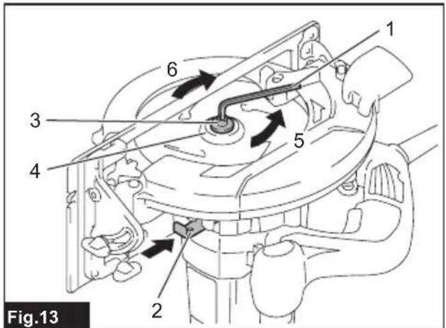
- To remove the circular saw blade, press the shaft lock fully so that the circular saw blade cannot revolve and use the hex wrench to loosen the hex bolt counterclockwise.
▶ Fig.13: 1. Hex wrench 2. Shaft lock 3. Hex bolt 4. Outer flange 5. Loosen 6. Tighten
-
Remove the hex bolt and outer flange.
-
Turn the lever to open the blade guard.
▶ Fig.14: 1. Lever
- Remove the blade and ring (country specific).
For tool without the ring
▶ Fig.15: 1. Hex bolt 2. Outer flange 3. Circular saw blade 4. Inner flange
For tool with the ring
▶ Fig.16: 1. Hex bolt 2. Outer flange 3. Circular saw blade 4. Ring 5. Inner flange
To install the circular saw blade, follow the removal procedure in reverse.
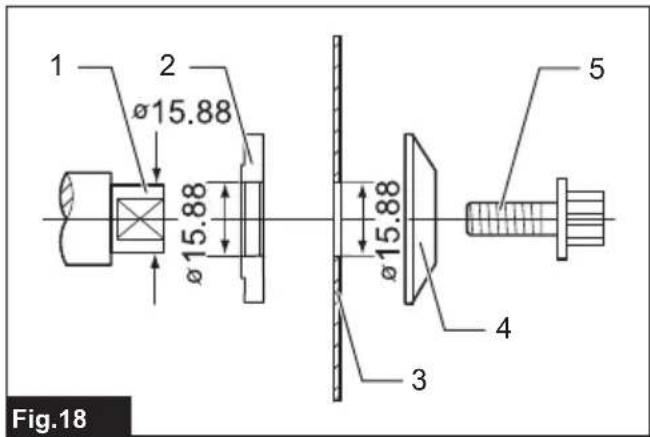
The inner flange has a certain diameter protrusion on one side of it and a different diameter protrusion on the other side. Choose a correct side on which protrusion fits into the saw blade hole perfectly. Mount the inner flange onto the mounting shaft so that the correct side of protrusion on the inner flange faces outward and then place saw blade and outer flange.
▶ Fig.17: 1. Mounting shaft 2. Inner flange 3. Circular saw blade 4. Outer flange 5. Hex bolt
WARNING: BE SURE TO TIGHTEN THE HEX BOLT CLOCKWISE SECURELY. Also be careful not to tighten the bolt forcibly. Slipping your hand from the hex wrench can cause a personal injury.
WARNING: Make sure that the protrusion "a" on the inner flange that is positioned outside fits into the saw blade hole "a" perfectly. Mounting the blade on the wrong side can result in the dangerous vibration.
Mount the inner flange with its recessed side facing outward onto the mounting shaft and then place circular saw blade (with the ring attached if needed), outer flange and hex bolt.
▶ Fig.18: 1. Mounting shaft 2. Inner flange 3. Circular saw blade 4. Outer flange 5. Hex bolt
▶ Fig.19: 1. Mounting shaft 2. Inner flange 3. Circular saw blade 4. Outer flange 5. Hex bolt 6. Ring
WARNING: BE SURE TO TIGHTEN THE HEX BOLT CLOCKWISE SECURELY. Also be careful not to tighten the bolt forcibly. Slipping your hand from the hex wrench can cause a personal injury.
⚠ WARNING: If the ring is needed to mount the blade onto the spindle, always be sure that the correct ring for the blade's arbor hole you intend to use is installed between the inner and the outer flanges. Use of the incorrect arbor hole ring may result in the improper mounting of the blade causing blade movement and severe vibration resulting in possible loss of control during operation and in serious personal injury.
Blade guard cleaning
When changing the circular saw blade, make sure to also clean the upper and lower blade guards of accumulated sawdust as discussed in the Maintenance section. Such efforts do not replace the need to check lower guard operation before each use.
Hex wrench storage
When not in use, store the hex wrench as shown in the figure to keep it from being lost.
▶ Fig.20: 1. Hex wrench
Connecting a vacuum cleaner
Optional accessory
When you wish to perform clean cutting operation, connect a Makita vacuum cleaner to your tool using the dust nozzle.
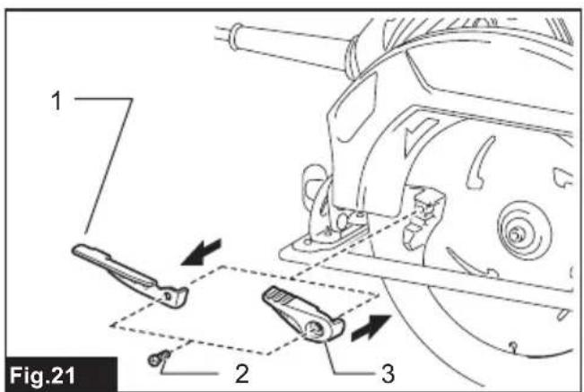
- If your circular saw has a long lever (country specific), replace it with the short lever supplied with the dust nozzle.
▶ Fig.21: 1. Long lever (country specific) 2. Screw 3. Short lever
Do not use the dust nozzle with the long lever attached. You will not be able to make a cut because the lower guard movement is hindered by the dust nozzle.
- Install the dust nozzle on the tool using the screw.
▶ Fig.22: 1. Dust nozzle 2. Screw
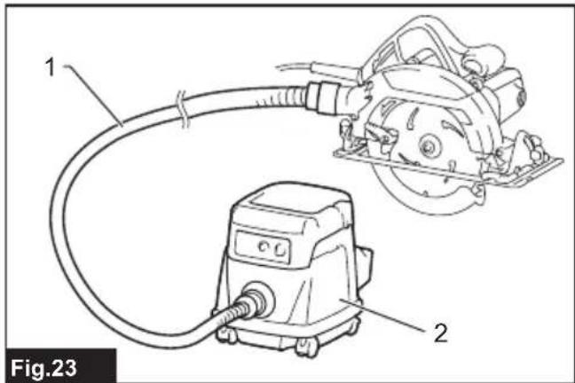
- Connect a hose of the vacuum cleaner to the dust nozzle.
▶ Fig.23: 1. Hose 2. Vacuum cleaner
OPERATION
⚠️ CAUTION: Wear dust mask when performing cutting operation.
CAUTION: Be sure to move the tool forward in a straight line gently. Forcing or twisting the tool will result in overheating the motor and dangerous kickback, possibly causing severe injury.
⚠️ CAUTION: Always use a front grip and rear handle and firmly hold the tool by both front grip and rear handle during operations.
▶ Fig.24
Hold the tool firmly. The tool is provided with both a front grip and rear handle. Use both to best grasp the tool. If both hands are holding saw, they cannot be cut by the circular saw blade. Set the base on the workpiece to be cut without the circular saw blade making any contact. Then turn the tool on and wait until the circular saw blade attains full speed. Now simply move the tool forward over the workpiece surface, keeping it flat and advancing smoothly until the sawing is completed.
To get clean cuts, keep your sawing line straight and your speed of advance uniform. If the cut fails to properly follow your intended cut line, do not attempt to turn or force the tool back to the cut line. Doing so may bind the circular saw blade and lead to dangerous kickback and possible serious injury. Release switch, wait for circular saw blade to stop and then withdraw tool. Realign tool on new cut line, and start cut again. Attempt to avoid positioning which exposes operator to chips and wood dust being ejected from saw. Use eye protection to help avoid injury.
Rip fence (Guide rule)
Optional accessory
▶ Fig.25: 1. Rip fence (Guide rule) 2. Clamping screw
The handy rip fence allows you to do extra-accurate straight cuts. Simply slide the rip fence up snugly against the side of the workpiece and secure it in position with the clamping screw on the front of the base. It also makes repeated cuts of uniform width possible.
MAINTENANCE
⚠️CAUTION: Always be sure that the tool is switched off and unplugged before attempting to perform inspection or maintenance.
⚠️CAUTION: Clean out the guard to ensure there is no accumulated sawdust and chips which may impede the operation of the guarding system. A dirty guarding system may limit the proper operation which could result in serious personal injury. The most effective way to accomplish this cleaning is with compressed air. If the dust is being blown out of the guard, be sure the proper eye and breathing protection is used.
NOTICE: Never use gasoline, benzine, thinner, alcohol or the like. Discoloration, deformation or cracks may result.
Adjusting the parallelism
This adjustment has been made at the factory. But if it is off, you can adjust it as the following procedure.
- Set the tool to the maximum cutting depth.
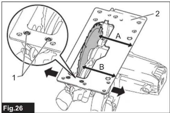
- Make sure all levers and screws are tightened. Slightly loosen the screw illustrated.
▶ Fig.26: 1. Screw 2. Base
- While opening the lower guard, move the rear of the base so that the distance A and B becomes equal.
- Tighten the screws and make a test cut to check the parallelism.
Adjusting 0°-cut accuracy
This adjustment has been made at the factory. But if it is off, you can adjust it as the following procedure.
- Slightly loosen the clamping screws on the front and rear of the tool.
- Make the base perpendicular to the blade using a triangular rule or square rule by turning the adjusting screw.
▶ Fig.27: 1. Triangular rule 2. Base 3. Adjusting screw 4. Clamping screw
- Tighten the clamping screws and then make a test cut to check the verticalness.
Replacing carbon brushes
▶ Fig.28: 1. Limit mark
Check the carbon brushes regularly.
Replace them when they wear down to the limit mark.
Keep the carbon brushes clean and free to slip in the holders. Both carbon brushes should be replaced at the same time. Use only identical carbon brushes.
- Use a screwdriver to remove the brush holder caps.
- Take out the worn carbon brushes, insert the new ones and secure the brush holder caps.
▶ Fig.29: 1. Brush holder cap
To maintain product SAFETY and RELIABILITY,
repairs, any other maintenance or adjustment should be performed by Makita Authorized or Factory Service Centers, always using Makita replacement parts.
OPTIONAL ACCESSORIES
CAUTION: These accessories or attachments are recommended for use with your Makita tool specified in this manual. The use of any other accessories or attachments might present a risk of injury to persons. Only use accessory or attachment for its stated purpose.
If you need any assistance for more details regarding these accessories, ask your local Makita Service Center.
- Circular saw blade
- Rip fence (Guide rule)
- Hex wrench
• Dust nozzle (with lever)
• Dust nozzle (without lever)
- Guide rail
- Clamp
- Sheet
- Rubber sheet
- Position sheet
- Guide rail adapter
- Rule bar
NOTE: Some items in the list may be included in the tool package as standard accessories. They may differ from country to country.
SPÉCIFICATIONS
▶ Fig.23: 1. Tuyau 2. Aspirateur
UTILISATION
▶ Fig.26: 1. Vis 2. Base
▶ Abb.20: 1. Inbusschlüssel
▶ Fig.26: 1. Vite 2. Base
⚠ WAARSCHUWING: Draag gehoorbescherming.
VEILIGHEIDSWAAR- SCHUWINGEN
▶ Fig.23: 1. Slang 2. Stofzuiger
BEDIENING
OPTIONELE ACCESSOIRES
▶ Fig.20: 1. Llave hexagonal
▶ Fig.20: 1. Chave hexagonal
Ligar um aspirador
Acessório opcional