
CQR253U - Car stereo PANASONIC - Free user manual and instructions
Find the device manual for free CQR253U PANASONIC in PDF.
User questions about CQR253U PANASONIC
0 question about this device. Answer the ones you know or ask your own.
Ask a new question about this device
Download the instructions for your Car stereo in PDF format for free! Find your manual CQR253U - PANASONIC and take your electronic device back in hand. On this page are published all the documents necessary for the use of your device. CQR253U by PANASONIC.
USER MANUAL CQR253U PANASONIC
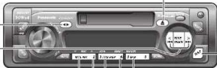
Removable Face High-Power Cassette/Receiver with Changer Control
TO REDUCE THE RISK OF FIRE OR ELECTRIC SHOCK OR PRODUCT DAMAGE,DO NOT EXPOSE THIS APPLIANCE TO RAIN, SPLASHING, DIIPPING OR MOISTURE.
CAUTION:
PLEASE FOLLOW THE LAWS AND REGULATIONS OF YOUR STATE, PROVINCE OR COUNTRY FOR INSTALLATION OF THE UNIT.
The following applies only in the U.S.A.
Part 15 of the FCC Rules
FCC Warning:
Any unauthorized changes or modifications to this equipment would void the user's authority to operate this device.
NOTICE:
This product contains lead in some components. Disposal of these materials may be regulated in your community due to environmental considerations.
For disposal or recycling information please contact your local authorities, or the Electronics Industries Alliance: http://www.eiaea.org.
Find the model number and serial number on either the back or bottom of the unit. Please record them in the space below and retain this booklet as a permanent record of your purchase to help with identification in case of theft.
MODEL NUMBER CO-R253U SERIAL NUMBER
DATE PURCHASED FROM
Panasonic welcomes you to our ever growing family of electronic product owners. We know that this product will bring you many hours of enjoyment. Our reputation is built on precise electronic and mechanical engineering, manufactured with carefully selected components and assembled by people who take pride in their work. Once you discover the quality, reliability, and value we have built into this product, you too will be proud to be a member of our family.
Use this Product Safely
When Driving
Keep the volume level low enough product to be aware of road and traffic conditions.
When Washing your car
Do not expose the product, including the speakers and tapes, to water or excessive moisture. This could cause electrical shorts, fire, or other damage.
When Parked
Parking in direct sunlight can produce very high temperatures inside your car. Give the interior a chance to cool down before switching the unit on.
Use the Proper Power Supply
This product is designed to operate of a 12 volt DC negative ground battery system (the normal system in a North American car.)
Protect the Tape Mechanism
Keep magnets, screwdrivers, or other metallic objects away from the tape mechanism and tape head to prevent poor performance or malfunctions.
Use Authorized Serviccenters
Do not attempt to disassemble or adjust this precision product. Please refer to the Servicemember list included with this product for service assistance.
-Operating Instructions 1
Supplied Hardware. 1set ( page 22)
Remote Control Unit 1
Lithium Battery (CR2025) 1
- Removable face plate case 1
Warranty Card. 1
□Accessoires
NOTICE 2
Use This product Safely 4
Accessories 4
General 10
Power, volume, mute, loudness and audio mode
(Bass/Treble/Balance/Fader)
Clock Setting 11
Initial time and time reset
□ Radio 12
Radio mode, band, manual tuning, seek tuning, mono selection, preset station setting, preset
station calling and display change
Cassette Tape Player 14
How to load, Rewind, Fast forward, play side change, eject a cassette tape and display change
□ CD Changer Control 16
Play, repeat, random, scan, error messages and display change
Note: CD changer controls are applicable to units with optional CD changer unit (sold separately)
Remote Control 18
Battery installation, battery notes
Troubleshooting 19
Preliminary steps, if you suspect something wrong and troubleshooting tips
□ Speaker connections 21
Fuse 21
Product servicing 21
□ Maintenance. 21
□ Installation Guide 22
Remove the unit
□ Anti-Thelt System. 27
Place the removable face plate into case and install removable face plate
Electrical Connections 28
Caution and wiring diagram
□ Specifications. 29
Table des matieres
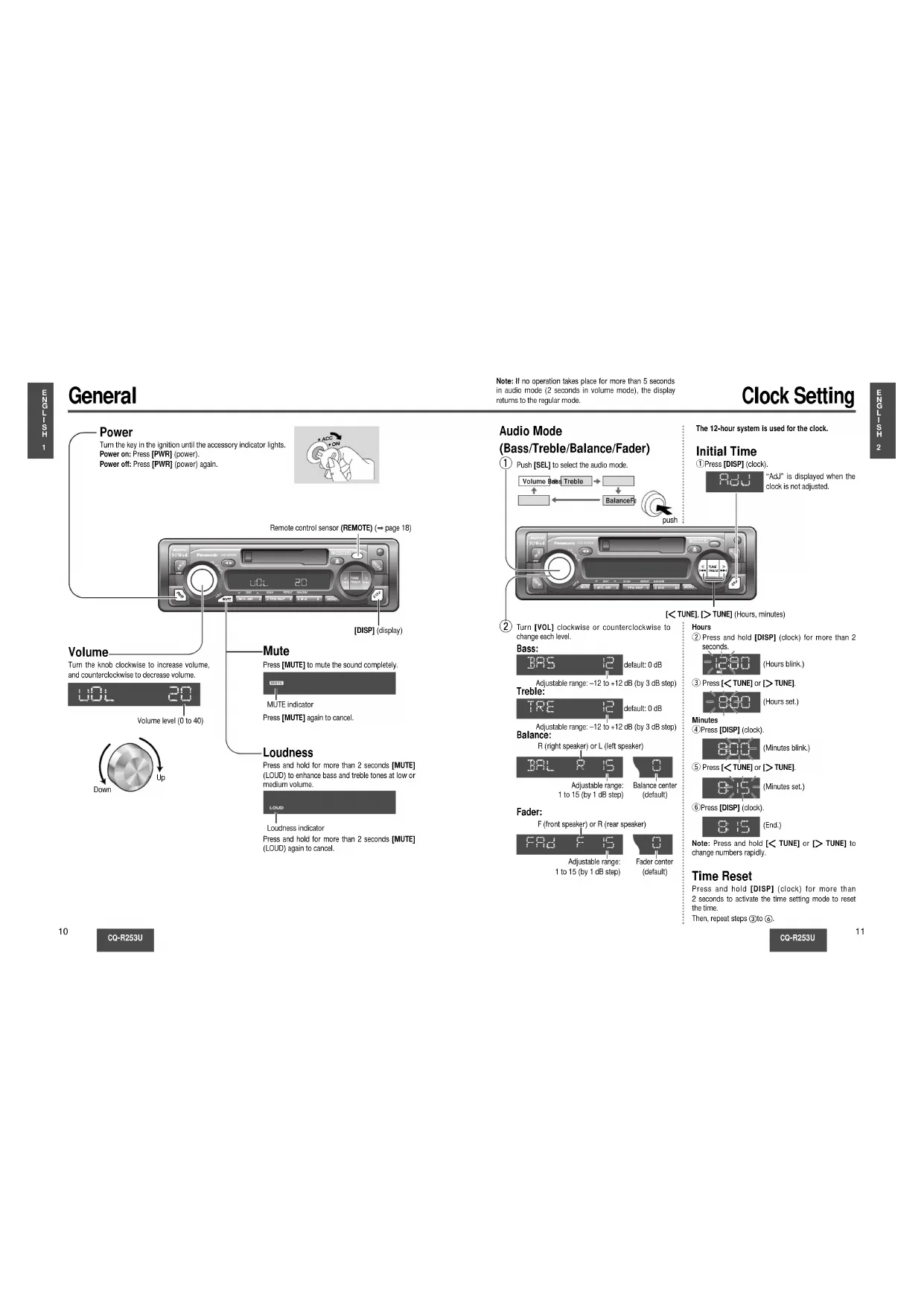
Note: If no operation takes place for more than 5 seconds in audio mode (2 seconds in volume mode), the display returns to the regular mode.
Clock Setting
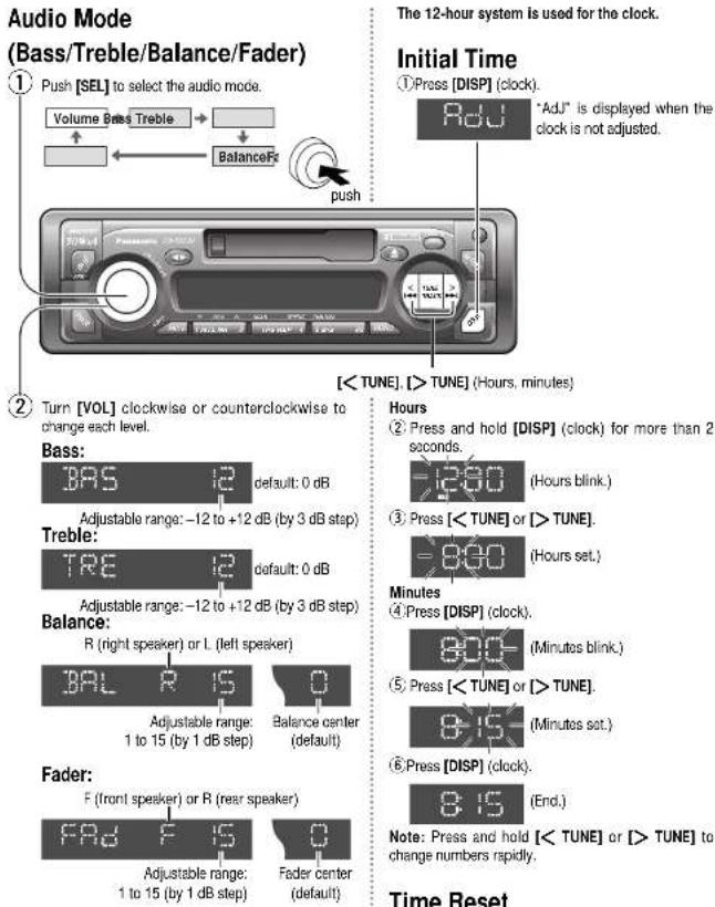
Time Reset
Press and hold [DISP] (clock) for more than 2 seconds to activate the time setting mode to reset the time. Then, repeat stops ③to ⑥.
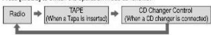
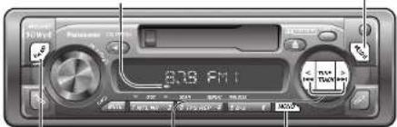
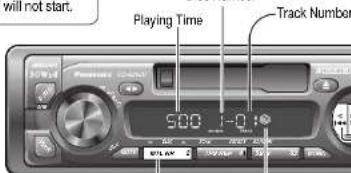
Radio
① Radio mode
Press [MODE] to switch the operation mode as follows:
FM stereo Indicator
② Band
③ Manual Tuning
TUNE:Higher frequency
T> TUNE: Lower frequency
Seek Tuning
Press and hold for more than 0.5 second.
[TUNE]: Higher frequency
Tuning will automatically stop when the signals
of the next broadcast station are received.
④ Mono Selection
Pross [MONO] for monaural reception in case a lot of interference is present in an FM stereo signal or to improve the listening quality of weak FM broadcasts. Press [MONO] again to cancel.

MONO indicator
CQ-R253U
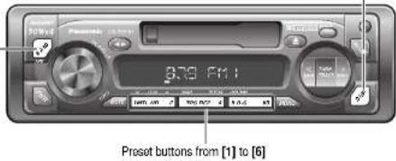
Preset Station Setting
Up to 6 stations can be saved in each of the FM1, FM2, FM3 and AM onset station memories.
Note: Existing saved stations are overwritten with new stations after following this procedure.

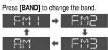
Band
Press [BAND] to select a desired band.
(→ page 12)
② Auto Preset Memory (APM)
Press and hold [BAND] (APM: auto preset memory) for more than 2 seconds.
- The 6 stations with good reception will be automatically saved in the memory under preset buttons from [1] to [6].
- Once set, the preset stations are sequentially scanned for 5 seconds each.
Manual Preset Memory
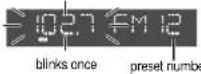
Use manual or seek tuning to find a station. ( page 12) Press and hold one of the preset buttons from [1] to [6] until the display glinks once.
Preset Station Calling
Press the corresponding preset button from [1] to [6] to tune in a preset station.
aution: To ensure safety, never attempt to preset stations while you are driving.
Display Change
Press [DISP] (display) to switch to the clock display.


CQ-R253U
Cassette Tape Player
Loading a Cassette
Insert the cassette with the exposed tape side facing to the right. Gently push the cassette in until the loading begins. The cassette will be loaded in place and playback starts.
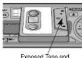
Caution: Do not insert a tape when "tape" indicator "A" or "C" lights.
Note: To maintain your cassette player in top condition, avoid using tapes that are longer than 90 minutes (C-90).
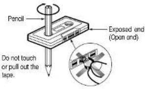
Notes on Cassette Tapes
Tape Slack:
Use a pencil or similar object to take up the slack as shown. If a loose tape is used, this may result in the tape becoming tangled in the rotating parts of the unit.
Ejecting the Tape
Press [A] and the cassette will eject for removal, and the previous mode of operation will be resumed. Notes:
- If power is switched off before [] is pressed, the cassette will not eject. Switch on the power again and press [] to eject the cassette.
- The cassette tape should always be removed from the cassette slot when not in use.
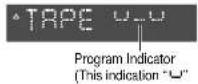
Play Side Change
Press [ ] to switch to the program on the other side of the tape. The display changes to indicate which program is playing.

Too Side Playing

Bottom Slice Playing
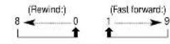
Rewind and Fast Forward
Pressor [TRACK] to [TRACK] activate rewind or fast forward of the tape.

plinks
Press [ ] to stop rewind or fast forward.
If you rewind the tape fully, it will play on the same program side again.
If you fast forward to the end, play will resume from the beginning of the other side of the tape.
Metal Tape Mode
Press [1] (MTL) when playing metal or chromium dioxide (CrCo) tapes. Press [1] (MTL) again to cancel.

Note: Playing normal tapes in metal tape mode mode causes high frequency imbalance, which affects tone quality.
Dolby B Noise Reduction
Press [2] (NR) to set the Dolly B-NR mode. Press [2] (NR) again to cancel.

Note: Set the Dolby B NR mode when playing back a tape recorded with Dolby B Noise Reduction.
Tape Program Search (TPS)-Operation
① Press [3] (TPS) to activate the tape program search mode.

To select a desired program, press [TRACK] or [TRACK] corresponding times to go forward (up to 9) or backward (up to 8).
③ To turn it off, press [3] (TPS) again.
Blank Skip
Press [5] (B-S) to skip unrecorded portions longer than 15 seconds on the tape. Press [5] (B-S) again to cancel.

Note: When repeat is on, the blank skip does not work because the repeat has priority over the blank skip.
Repeat Play
Press [4] (REP) to repeat the current program.


Note: The TPS and B-S mode may not work correctly in the following cases. This, however, does not mean that the unit is defective.
- There is an interval less than 3 (15 in B+S mode) seconds or having a high level of noise or hum between programs.
There is particularly low-level passage during the program.
Display Change
Press [DISP] (display) to switch to the clock display.

Tape
Clock display
CD Changer Control
①CDChangermode
While a disc magazine is inserted in the CD changer, press [MODE]. Play starts from the first track.
Note: The cassette, if loaded, should be removed. Otherwise, the CD play will not start.
②Disc Selection
[1](V DISC): Previous disc.
[2](△DISC): Next disc.
③Track Selection
Press [TRACK] once to go to the next track. Press repeatedly to step forward through all the tracks. Press [TRACK] once to play from the beginning of the current track. Press twice to play the previous track. Press repeatedly to stop backward through all the tracks.
Track Search
Press and hold [TRACK ] or [TRACK ] for more than 0.5 second to activate fast forward or reverse through a track. Release it to resume the normal CD play from that position.
Display change
Press [DISP] (display) to switch to the clock display.

CD Changer display
Clock display
CQ-R253U
Note:
CD changer functions are applicable to units with optional CD changer unit. (sold separately)
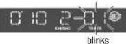
Scan Play (Tracks)
- Press [3] (SCAN), The track number blinks and the first 10 seconds of each track on the discs play in sequence.
- Press [3] (SCAN) again to cancel and continue with the current track.
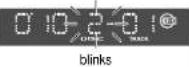
Scan Play (Discs)
- Press and hold [3] (SCAN) for more than 2 seconds. The first track of all the discs in the magazine is played for 10 seconds each and Disc Number blinks.
- Press and hold [3] (SCAN) for more than 2 seconds again to cancel.
Repeat Play
- Press [4] (REPEAT) to repeat the current selection.
- Press [4] (REPEAT) again to cancel.
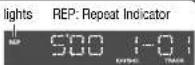
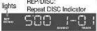
Repeat Play (Discs)
- Press and hold [4] (REPEAT) for more than 2 seconds to repeat the current Disc. "REP/DISC" indicator lights.
- To cancel, press [4] (REPEAT) for more than 2 seconds again.
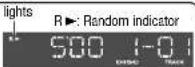
Random Play
- Press [5] (RANDOM) to random selection of music is played from all available CDs.
- Press [5] (RANDOM) again to cancel.
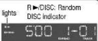
Random Play (Discs)
- Press and hold [5] (RANDOM) for more than 2 seconds to random selection of music is played from the current Disc. "▶/DISC" indicator lights.
- To cancel, press [5] (RANDOM) for more than 2 seconds again.
Error Display Messages

Disc is dirty, or is upside down.
Select the next available compact disc. Check the disc.


Disc has scratches.
Select the next available compact disc. Check the disc.


Eject the magazine. If failure persists, press the reset switch on the CD changer. If normal operation is not restored yet, call the store where you purchased the unit.

No disc in the changer (magazine)
Insert discs into the changer (magazine).
CG-B253U
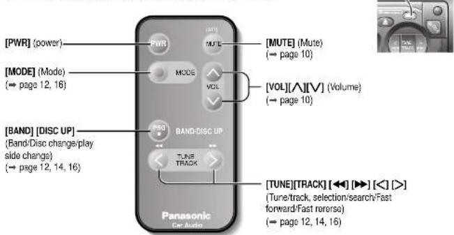
Remote Control
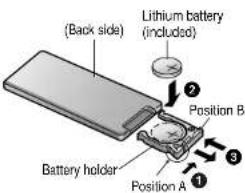
Battery Installation
1 Remove the battery holder.
Press and position A of the battery holder and then pull it out.
Install the battery on the battery holder.
Place a battery in the holder with its "+-" side facing up as shown in the figure.
Insert the battery holder.
Push the battery holder back into its original position.
Battery Notes
Remove and dispose of an old battery immediately. Battery Information:
- Battery type: Panasonic lithium battery (CR2025) (included)
Battery life: Approximately 6 months with normal use (at room temperature)
Caution:
-
Improper use of batteries may cause overheating, an explosion or ignition, resulting in injury or a fire. Battery leakage may damage the unit.
-
Do not disassemble or short the battery. Do not throw a battery into a fire.
- Keep batteries away from children to avoid the risk of accidentally
- Keep batteries away from children to avoid the risk of accidents.
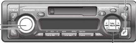
Control Reference Guide
Buttons of the remote control function in the same way as the controls on the main unit of the reference page.
Point the remote control unit at the main unit's sensor (REMOTE).
C0-R253U
Troubleshooting
Preliminary Steps
Check and take steps as described in the tables below.
If You Suspect Something Wrong
Immediately switch the power off.
Disconnect the power connector and check that there is neither smoke nor heat from the unit before asking for repairs. Never try to repair the unit by yourself because it is dangerous to do so.
Caution:
- Do not use the unit if it malfunctions or if there is something wrong.
- Do not use the unit In irregular condition, for example, without sound, or with smoke or foul smell, which can cause ignition or electric shock. Immediately stop using it and call the store where you purchased it.
Troubleshooting Tips
Common
Trouble
Cause/Step
No power.

Car's engine switch is not on.
Turn your car's ignition switch to ACC or ON.
Cables are not correctly connected.
Connect cables correctly.
Battery cable is not correctly connected.
Connect the battery cable to the terminal that is always active.
Accessory cable is not correctly connected.
Connect the accessory cable to your car's ACC source.
Grounding wire is not correctly connected.
Connect the grounding wire to a metal part of the car.
Fuse is burnt.
Consult the store where you purchased the unit and ask for fuse
replacement.
Mute is set to CN.
Set it to OFF.
Cables are not correctly connected.
Connect cables correctly.
The ground Lead is not connected properly.
Connect the Ground Lead properly.
No sound.
Noise.

Radio
Trouble
Much noise in FM stereo
and monaura
broadcasts.
Preset station is reset.
Cause/Step
The Antenna ground earth is not connected properly.
Connect the Antenna ground earth properly.
The radio antenna is not extended enough.
Extend fully the radio antenna.
Battery cable is not correctly connected.
Connect the battery cable to the terminal that is always active.
CG-R253U
Troubleshooting (continued)
Cassette Tape
Trouble
No sound.
Tape sound quality is poor.
High tones are improperly emphasized.
Reproduction of high tones is poor.
Wow and flutter level is very high.
Sound Setting
Trouble
No sound from left, right, front, or rear speakers.
Left and right sounds are reversed in stereo listening.
Blank tape is inserted in the unit. Insert recorded tape into the unit.
Heads are dirty.
Clean heads. (Ask a service representative for advice.)
Poor quality tape.
Use better quality tape.
Dolby B NR tape plays with Dolby B NR off. Set Dolby B NR to ON.
Metal type tape plays with normal mode. Change Normal mode to Metal mode.
Non-Dolby B NR tape plays with Dolby B NR on. -Set Dolby B NR to OFF.
Normal type tape plays with Metal mode. Change Metal mode to Normal mode
Heads are macnetized.
Demagnetize heads. (Ask a service representative for advice.)
Tape running mechanism is dirty or out of order.
Clean tape running mechanism, or repair it. (Ask a service representative for advice.)
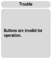
Remote Control Unit
Trouble
Buttons are invalid for operation.
Unit

Cause/Step
Left and right balance, or front and rear balance is off on one side. Adjust balance/fader setting as appropriate.
Cables are not correctly connected.
Connect the cables correctly.
The right speaker wire is connected to the left speaker and the left speaker wire to the right speaker.
Connect the speaker wires to the correct one.
Cause/Step
Battery poles (+) (-) are reversed.
Insert the battery correctly.
Wrong battery.
-Check the battery.
Battery has run
Replace the battery.
Remote control is in the wrong direction.
Direct the remote control at sensor (REMOTE) on the panel.
CG-R253U
Speaker Connections
Caution: Please follow the instructions given below. Failure to do so will cause damage to the unit and speakers.
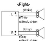
- Use ungrounded speaker only.
- The maximum speaker input should be 50 W or more. (If used with the optional power amplifier, the speaker input should be higher than the maximum amplifier output.)
The speaker impedance should be 4-8Ω. - This unit uses the BTCL circuit, so each speaker should be connected separately using parallel vinyl insulated cords.
- The speaker cords and the power amplifier unit should be kept away (about 30 cm apart) from the antenna and antenna extension cord.
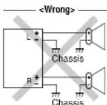

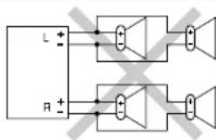
-
Never connect the speaker cord to the body of the car.
-
Do not use a 3-wire type speaker system having a common earth lead.
-
Do not connect more than one speaker to one set of speaker leads.
Fuse
Use fuses of the same specified rating (15 A). Using different substitutes or fuses with higher ratings, or connecting the unit directly without a fuse, could cause fire or damage to the unit.
If the fuse replacement fails, contact your nearest authorized Panasonic Service Center.
Product Servicing
If the suggestions in the charts do not solve the problem, we recommend that you take it to your nearest authorized Panasonic Servocenter. The product should be serviced only by a qualified technician.
Maintenance
Your product is designed and manufactured to ensure the minimum of maintenance. Use a soft cloth for routine exterior cleaning. Never use benzine, thinner, or other solvents.
CQ-R253U
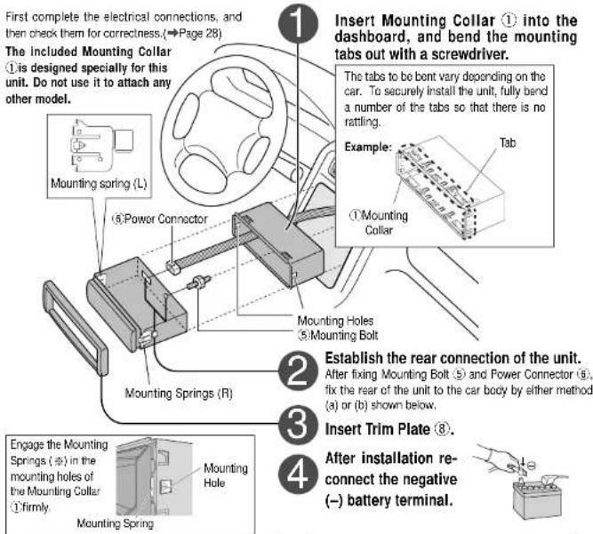
Installation Guide

WARNING
This installation information is designed for experienced installers and is not intended for non-technical Individuals. It does not contain warnings or cautions of potential dangers involved in attempting to install this product.
Any attempt to install this product in a motor car by anyone other than qualified installer could cause damage to the electrical system and could result in serious personal injury or death.
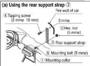
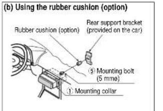
Installation Hardware
| No. | Item | Diagram | Q'ty |
| ① | Mounting collar | 1 | |
| ② | Hex. nut (5 mmo) | 1 | |
| ③ | Rear support strap | 1 | |
| ④ | Tapping screw(5 mmo - 16 mm) | 1 | |
| ⑤ | Mounting bolt (5 mmo) | 1 | |
| ⑥ | Power connector | 1 | |
| ⑦ | Dismounting plate | 2 | |
| ⑧ | Trim plate | 1 |
Overview
This product should be installed by a professional. However, if you plan to install this product yourself, your first step is to decide where to Install It. The instructions in these pages will guide you through the remaining steps:
(Pleaseseretothe"WARNINGstatementabove.)
- Identify and label the car wires.
- Connect the car wires to the wires of the power connector.
Install the unit in the dashboard. - Check the operation of the unit.
If you encounter problems, please consult your nearest professional installer.
Caution:
- This unit operates with a 12 V DC negative ground auto battery system only. Do not attempt to use it in any other system. Doing so could cause serious damage.
Before you begin installation, look for the items which are packed with your unit.
Warranty Card...Fill this out promptly.
- Panasonic Servicenter List for Service Directory ...Keep for future reference in case the product needs servicing.
- Installation Hardware...Needed for in-dash installation.
Required Tools
You'll need a screwdriver, a 1.5 V AA battery, and the following:
12VDC
Test bulb
Electrical tape Side-cut
pilers


Identify All Leads
The first step in installation is to identify all the car wires you'll use when hooking up your sound system. As you identify each wire, we suggest that you label it using masking tape and a permanent marker. This will help avoid confusion when making connections later.
Note: Do not connect the power connector to the stereo unit until you have made all connections. If there are no plastic caps on the stereo hooking wires, insulate all exposed leads with electrical tape until you are ready to use them. Identify the leads in the following order.
Power Lead
If your car has a radio or is pre-wired for one:
Cut the connector wires one at a time from the plug (leaving the leads as long as possible) so that you can work with individual leads.


Turn the ignition on to the accessory position, and ground one lead of the test bulb to the chassis.
Touch the other lead of the test bulb to each of the exposed wires from the cut radio connector plug. Touch one wire at a time until you find the outlet that causes the test bulb to light.
Now turn the ignition off and then on. If the bulb also turns off and on, that outlet is the car power lead.
If your car is not wired for an audio unit:
Go to the fuse block and find the fuse port for radio (RADIO), accessory (ACC), or ignition (IGN).
Battery Lead
If your stereo unit has a yellow lead, you will need to locate the car's battery lead. Otherwise you may ignore this procedure. (The yellow battery lead provides continuous power to maintain a clock, memory storage, or other function.)
If your car has a radio or is pre-wired for one:
With the ignition and headlights off, identify the car battery lead by grounding one lead of the test bulb to the chassis and checking the remaining exposed wires from the cut radio transmitter plug.
If your car is not wired for an audio unit:
Go to the fuse block and find the fuse port for the battery, usually marked BAT.
Speakers
Identify the car speaker leads. There are two leads for each speaker which are usually color coded.
A handy way to identify the speaker leads and the speaker they are connected with is to test the leads using a 1.5 V AA battery as follows.
Hold one lead against one pole of the battery and stroke the other lead across the other pole. You will hear a scraping sound in one of the speakers if you are holding a speaker lead.
If not, keep testing different lead combinations until you have located all the speaker leads. When you label them, include the speaker location for each.
Antenna
The antenna lead is a thick, black wire with a metal plug at the end.

Connect All Leads
Now that you have identified all the wires in the car, you are ready to begin connecting them to the stereo unit wires. The wiring diagram ( 一 page 28) shows the proper connections and color coding of the leads.
We strongly recommend that you test the unit before making a final Installation.
You can set the unit on the floor and make temporary connections to test the unit. Use electrical tape to cover all exposed wires.
Important: Connect the red power load last, after you have made and insulated all other connections.
Ground
Connect the black ground lead of the power connector to the metal car chassis.
Installation Guide (Continued)
Speakers
Connect the speaker wires. See the wiring diagram ( page 28) for the proper hookups. Follow the diagram carefully to avoid damaging the speakers and the stereo unit.
The speakers used must be able to handle more than 50 W of audio power. If using an optional audio amplifier, the speakers should be able to handle the maximum amplifier output power. Speakers with low input ratings can be damaged. Speaker impedances should measure 4 - 8 which is typically marked on most speakers. Lower or higher impedance speakers will affect output and can cause both speaker and stereo unit damage.
Battery
Connect the yellow battery lead to the correct radio wire or to the battery fuse port on the fuse block.
Antenna
Connect the antenna by plugging the antenna lead into the antenna receptacle.
Equipment
Connect any optional equipment such as an amplifier, according to the instructions furnished with the equipment. Leave about 12^ (30 cm) of distance between the speaker leads/amplifier unit and the antenna/anlenna extension cord. Read the operating and installation instructions of any equipment you will connect to this unit.
Power
Connect the red power lead to the correct car radio wire or to the appropriate fuse port on the fuse block.
If the stereo unit functions properly with all these connections made, disconnect the wires and proceed to the final installation.
Final Installation
Lead Connections
Connect all wires, making sure that each connection is insulated and secure. Bundle all loose wires and fasten them with tape so they will not fall down later. Now insert the stereo unit into the mounting collar.
Congratulations! After making a few final checks, you're ready to enjoy your new auto stereo system.
Final Checks
- Make sure that all wires are properly connected and insulated.
- Make sure that the stereo unit is securely held in the mounting collar.
- Turn on the ignition to check the unit for proper operation.
If you have difficulties, consult your nearest authorized professional installer for assistance.
Preparation
- We strongly recommend that you wear gloves for installation work to protect yourself from injuries.
- When bending the mounting tabs of the mounting collar with a screwdriver, be careful not to injure your hands and fingers.
- Disconnect the cable from the negative Battery terminal (see cautions below).
- Unit should be installed in a horizontal position with the front end up at a convenient angle, but not more than 30^ .
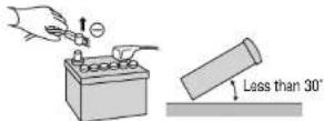
Caution: Do not disconnect the battery terminals of a car with a trip or navigational computer since all user settings stored in memory will be lost. Instead take extra care with installing the unit to prevent shorts.
Dashboard Installation
Installation Opening
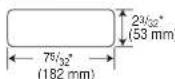
This unit can be installed in any dashboard having an opening as shown above. The dashboard should be 1 / 2 (4.75 mm) - 1 / 2 (5.56 mm) thick in order to be able to support the unit.
CQ-R253U
Cautions:
- We strongly recommend that you wear gloves for installation work to protect yourself from injuries.
- When bending the mounting tab of the mounting collar with a screwdriver, be careful not to injure your hands and fingers.
CQ-R253U
25
Installation (Continued)
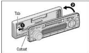
To Remove the Unit
Switch off the power of the unit.
1 Remove the removable face plate.
1 Press [ ] . (release button). The removable face plate will be released.
Release button
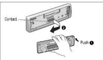
2 Remove the Trim Plate with a screwdriver.
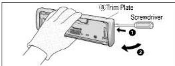
Insert the Dismounting Plates. along the grooves on both sides of the main unit until "click" is heard.
Pull out the unit while pushing the plates further inside.
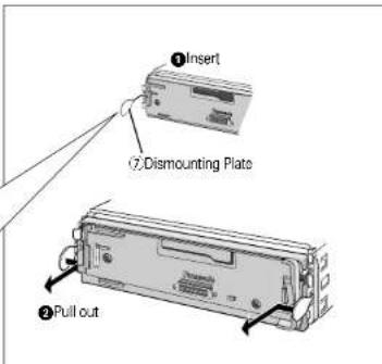
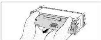
4 Remove the unit pulling with both hands.
C0-R253U
Anti-Theft System
This unit is equipped with a removable face plate. Removing this face plate makes the radio totally inoperable.
Place the Removable Face Plate into Case
Switch off the power of the unit
Remove the removable face plate. (→ page 26)
Gently press the bottom of the case and open the cover. Place the face plate into the case and take it with you when you leave the car.
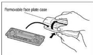
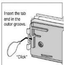
Install Removable Face Plate
Slide the left side of the removable face plate in place.
Press the right end of the removable face plate until "click" is heard.
Caution:
This face plate is not waterproof. Do not expose it to water or excessive moisture.
- Do not remove the face plate while driving your car.
- Do not place the face plate on the dashboard or nearby areas where the temperature rises to high level.
Do not touch the contacts on the face plate or the main unit, since this may result in poor electrical contacts.
If dirt or other foreign substances get on the contacts, wipe them off with a clean and dry cloth.
CQ-R253U
Electrical Connections
Preparation:
This unit can be connected to an optional CD changer (CX-DP880U). For details consult your nearest Panasonic servipentar.
For connection to a CD changer, refer to the operating instructions of the CD Changer (CX-DP860U).
Cautions:
- To prevent damage to the unit, be sure to follow the connection diagram below.
- Remove the covering of the leads about 5 mm long from their end before connecting
- Do not insert the power connector into the unit until the wiring is completed.
- Be sure to insulate any exposed wires from a possible short-circuit from the car chassis. Bundle all cables and keep cable terminals free from touching any metal parts.
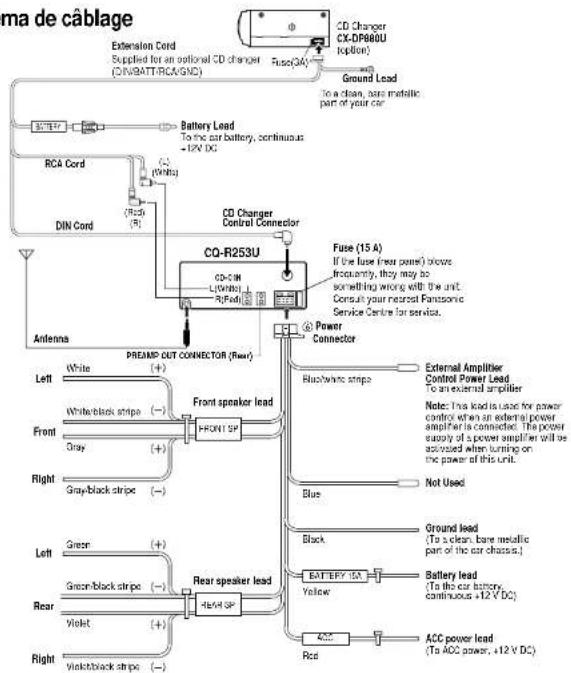
Scheme de cablage
Specifications
□ General
Power Supply: 12 V DC (11 V - 16 V) Test Voltage 14.4 V, Negative ground
Maximum Power Output: 50 W - 4 channels at 400 Hz, Volume Control maximum
Tone adjustment range: 0-1000
BASS:±1208at100Hz
Trelle: ± 12 dB at 10kHz
Current Consumption: Less than 2 A (ca)
Pre-Amp Output Voltage: 2.0 V (CD Play mode; 1KHz)
Suitable Speaker Impedance: 4-8Ω Dimensions (W-H-D):
Weight: 3 lbs. 1 oz (1.4 kg)
□AM Radio
Frequency Range: 530-1710 kHz
Useable Sensitivity: 28 dBuV (25 V, S/N 20 dB)
FM Stereo Radio
Frequency Range: 87.9 - 107.9 MHz
Useable Sensitivity: 13.2 dBf. (1.25 μV, 75 Ω)
50 dB Cuiating Sensitivity: 15.2 dBf. (1.8 μV, 75 Ω)
Frequency Response: 30 - 15 000 Hz (±3 dB)
CapeRtio:
Alternate Channel Selectivity
Stereoseparation. Image Response Ratio:
IF Responcy Ratio: 100%
Signal/Noise Ratio:
Tape Player
Reproduction System:
Tape Speed:
FF/REW Time:
Frequency Response: 35 - 14 000 Hz ±3 dB (normal)
Wow and Flutter!
Signal/Noise Ratio:
62 dB (Dolby B NR ON)
Note: Specifications and design are subject to modification without notice due to improvements in technology.
Dolby noise reduction manufactured under license from Dolby Laboratories Licensing Corporation.
"DOLBY" and the double-D symbol are trademarks of Dolby Laboratories Licensing Corporation.
CQ-R253U
Généralités
Alimentation
TUNEL:Frquence plus elevated
[1](V DISC): Disque precedent.
(1) ( x - 2) ^2 = 9

Presiasonar

Gire [VOL] (volumen) hacla la derecha o Izqulerdar.
m = 311
edcr
(aI)
Panasonic Consumer ElectronicsCompany Division of Mobility
Electric Corporation of America
One Panaconic Way, Secaucus, New Jersey 07094
http://www.panassonic.com
Panasonic Sales Company. Division of Metals, El Paso, TX
Puerto Rico, Inc. ("PSC")
Ave. 65 de Infantaria, Km. 9.5 San Gabriel Industrial Park, Carolina,
Puerto Rico 00985 http://www.panasonic.com
Panasonic Canada Inc.
57/70 Amofer Drive, Mississauga, Ontario L4W 2T3
http://www.panasonic.ca