
CQRG153U - Car stereo PANASONIC - Free user manual and instructions
Find the device manual for free CQRG153U PANASONIC in PDF.
| Product type | Car stereo with cassette player and CD changer control |
| Brand | Panasonic |
| Model | CQ-RG153U |
| Dimensions (W x H x D) | 178 x 50 x 155 mm |
| Weight | 1.4 kg |
| Power supply | 12 V DC (11-16 V), negative ground |
| Current consumption | Less than 2.2 A |
| Maximum output power | 45 W x 4 channels (1 kHz, max volume) |
| Tone control range - Bass | ±12 dB at 100 Hz |
| Tone control range - Treble | ±12 dB at 10 kHz |
| Speaker impedance | 4-8 Ω |
| FM radio - Frequency range | 87.9 - 107.9 MHz |
| AM radio - Frequency range | 530 - 1710 kHz |
| Cassette player - System | 4-track, 2-channel stereo |
| Cassette player - Tape speed | 4.76 cm/s |
| Optional CD changer | Compatible (CX-DP88U, sold separately) |
| Detachable front panel | Yes, with storage case |
| Audio functions | Bass/treble/balance/fader, loudness control (LOUD), mute (MUTE) |
| Clock | 12-hour display, adjustable, reset |
| Tuning | Manual, seek, memory of 6 stations per band (FM1/FM2/FM3/AM) |
| Fuse | 15 A (use only specified rating) |
| Maintenance | Clean with a soft dry cloth; do not use solvents |
| Included accessories | Power connector, front panel case, manual, warranty card, installation hardware |
Frequently Asked Questions - CQRG153U PANASONIC
User questions about CQRG153U PANASONIC
0 question about this device. Answer the ones you know or ask your own.
Ask a new question about this device
Download the instructions for your Car stereo in PDF format for free! Find your manual CQRG153U - PANASONIC and take your electronic device back in hand. On this page are published all the documents necessary for the use of your device. CQRG153U by PANASONIC.
USER MANUAL CQRG153U PANASONIC
Removable Face High-Power Cassette/Receiver with Changer Control
natural_image
Black-and-white photo of a winding asphalt road through a grassy plain with distant hills (no text or symbols visible)- Please read these instructions carefully before using this product and keep this manual for future reference.
- Prière de lire ces instructions attentivement avant d'utiliser le produit et garder ce manuel pour l'utilisation ultérieure.
- Lea con atención estas instrucciones antes de utilizar el producto y guarde este manual para poderlo consultar en el futuro.
Safety Information
WARNING:
TO REDUCE THE RISK OF FIRE OR ELECTRIC SHOCK OR PRODUCT DAMAGE, DO NOT EXPOSE THIS APPLIANCE TO RAIN, SPLASHING, DRIPPING OR MOISTURE.
CAUTION:
PLEASE FOLLOW THE LAWS AND REGULATIONS OF YOUR STATE, PROVINCE OR COUNTRY FOR INSTALLATION OF THE UNIT.
The following applies only in the U.S.A.
Part 15 of the FCC Rules
FCC Warning:
Any unauthorized changes or modifications to this equipment would void the user's authority to operate this device.
NOTICE:
This product contains lead in some components. Disposal of these materials may be regulated in your community due to environmental considerations.
For disposal or recycling information please contact your local authorities, or the Electronics Industries Alliance: http://www.eiae.org.
Find the model number and serial number on either the back or bottom of the unit. Please record them in the space below and retain this booklet as a permanent record of your purchase to help with identification in case of theft.
MODEL NUMBER CQ-RG153U SERIAL NUMBER
DATE PURCHASED FROM
CQ-RG153U
| Safety Information (Part 15 of the FCC Rules)...... page 2 Notice...... 2 Use this Product Safely...... 7 Accessories...... 7 | |
| □ General...... 8 Power, volume, mute, loudness, audio mode (Bass/Treble/Balance/Fader) | |
| □ Clock Setting...... 9 Initial time, time reset | |
| □ Radio...... 10 Radio mode, band, manual tuning, seek tuning, mono selection, preset station setting, preset station calling, display change | |
| □ Cassette Tape Player...... 12 How to load, Rewind, Fast forward, play, eject a cassette tape and display change | |
| □ CD Changer Control...... 14 Play, repeat, random and scan, error messages Note: CD changer controls are applicable to units with an optional CD changer unit (sold separately). | |
| □ Troubleshooting...... 16 Preliminary steps, if you suspect something wrong, troubleshooting tips | ????! |
| □ Speaker connections...... 18 | |
| □ Fuse...... 18 | |
| □ Product servicing...... 18 | |
| □ Maintenance...... 18 | |
| □ Installation Guide...... 19 Installation hardware, overview, required tools, identify all leads. connect all leads, final installation, final checks, preparation, dashboard installation, to remove the unit | |
| □ Anti-Theft System...... 24 Place the removable face plate into case, install removable face plate | |
| □ Electrical Connections...... 25 Caution, wiring diagram | |
| □ Specifications...... 26 |
CQ-RG153U
Table des matières
Panasonic welcomes you to our ever growing family of electronic product owners. We know that this product will bring you many hours of enjoyment. Our reputation is built on precise electronic and mechanical engineering, manufactured with carefully selected components and assembled by people who take pride in their work. Once you discover the quality, reliability, and value we have built into this product, you too will be proud to be a member of our family.
□ Use this Product Safely
When Driving
Keep the volume level low enough to be aware of road and traffic conditions.
When Washing Your car
Do not expose the product, including the speakers and lapses, to water or excessive moisture. This could cause electrical shorts, fire, or other damage.
When Parked
Parking in direct sunlight can produce very high temperatures inside your car. Give the interior a chance to cool down before switching the unit on.
Use the Proper Power Supply
This product is designed to operate with a 12 V DC, negative ground battery system (the normal system in a North American car.)
Protect the Tape Mechanism
Keep magnets, screwdrivers, or other metallic objects away from the tape mechanism and tape head to prevent poor performance or malfunctions.
Use Authorized Servicenters
Do not attempt to disassemble or adjust this precision product. Please refer to the Servicenter list included with this product for service assistance.
□ Accessories
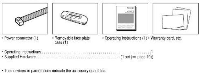
• Power connector (1)
- Removable face plate case (1)
- Operating instructions (1) - Warranty card, etc.
- Operating Instructions
• Supplied Hardware
.(1 set (→ page 19))
• The numbers in parentheses indicate the accessory quantities.
CQ-RG153U
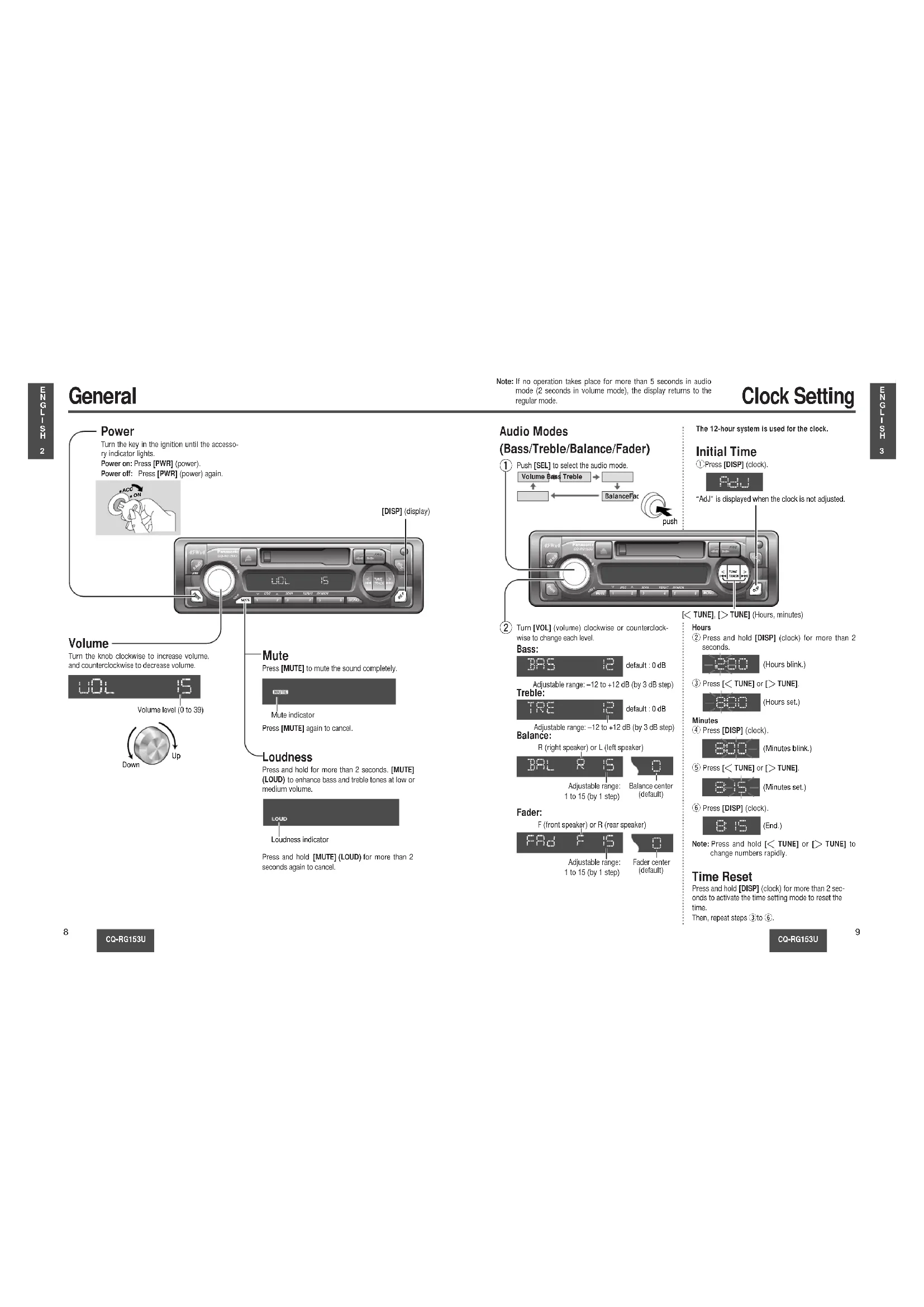
General
![Power Turn the key in the ignition until the accessory indicator lights. Power on: Press [PWR] (power). Power off: Press [PWR] (power) again. [DISP] (display) Volume Turn the knob clockwise to increase volume, and counterclockwise to decrease volume. Volume level (0 to 39) Down Up Mute Press [MUTE] to mute the sound completely. Mute indicator Press [MUTE] again to cancel. Loudness Press and hold for more than 2 seconds. [MUTE] (LOUD) to enhance bass and treble tones at low or medium volume. LOUD Loudness indicator Press and hold [MUTE] (LOUD) for more than 2 seconds again to cancel.](/content/2026/03/454466/images/3fbd04867dfdd5290b33ae0e9ef755eab1c3739805c3ba69b864f5e9523f0705.jpg)
CQ-RG153U
Note: If no operation takes place for more than 5 seconds in audio mode (2 seconds in volume mode), the display returns to the regular mode.
Clock Setting
Audio Modes
(Bass/Treble/Balance/Fader)
①
![Push [SEL] to select the audio mode. Volume Bars Treble BalanceFar push](/content/2026/03/454466/images/1951e5daa7d7dd36c554a9d449e95fb6fbb6577fff90c81dba17ee7215b00d5d.jpg)
②
Turn [VOL] (volume) clockwise or counterclockwise to change each level.
Bass:

Adjustable range: -12 to +12 dB (by 3 dB step) Treble:

Adjustable range: -12 to +12 dB (by 3 dB step) Balance:
R (right speaker) or L (left speaker)

Adjustable range: 1 to 15 (by 1 step)
Balance center (default)
Fader:
F (front speaker) or R (rear speaker)

Adjustable range: 1 to 15 (by 1 step)
Fader center (default)
The 12-hour system is used for the clock.
Initial Time
①Press [DISP] (clock)

"Adj" is displayed when the clock is not adjusted.
[< TUNE], [> TUNE] (Hours, minutes)
Hours
② Press and hold [DISP] (clock) for more than 2 seconds.
(Hours blink.)
③ Press [< TUNE] or [> TUNE].

(Hours set.)
Minutes
④ Press [DISP] (clock).

(Minutes blink.)
⑤ Press [< TUNE] or [> TUNE].

(Minutes set.)
⑥ Press [DISP] (clock).

(End.)
Note: Press and hold [< TUNE] or [> TUNE] to change numbers rapidly.
Time Reset
Press and hold [DISP] (clock) for more than 2 seconds to activate the time setting mode to reset the time.
Then, repeat steps ③ to ⑥
CQ-RG153U
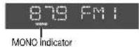
Radio
![① Change to the Radio mode Press [PWR] to change to the radio mode. ※Please press (▲) (reject) to eject the tape when cassette tape play mode start. FM stereo indicator 878 FMI ② Band Press [BAND] to change the band. PM1 → PM2 ↑ PM ← PM3 ③ Manual Tuning [> TUNE]: Higher frequency [< TUNE]: Lower frequency Seek Tuning Press and hold ... [> TUNE]: Higher frequency [< TUNE]: Lower frequency Tuning will automatically stop when the signals of the next broadcast station are received. ④ Mono Selection](/content/2026/03/454466/images/c3cbd2f02f67b89e33bb109fbc8363336564fc8fa334a4ee63bf010a9c8b7d43.jpg)
④ Mono Selection
Press [MONO] for monaural reception in case a lot of interference is present in an FM stereo signal or to improve the listening quality of weak FM broadcasts.
Press [MONO] again to cancel.
CQ-RG153U
Preset Station Setting
Up to 6 stations can be saved in each of the FM1, FM2, FM3 and AM preset station memories.
Note: Existing saved stations are overwritten with new stations after following this procedure.
Display Change
Press [DISP] (display) to switch to the clock display.
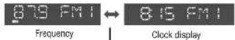

Band
Press [BAND] to select a desired band. (→ page 10)
![879:41 Preset buttons from [1] to [6]](/content/2026/03/454466/images/d7adc2b86aa52d2ae37850c345d01777004aeea0988d42929c552c2b921760cd.jpg)
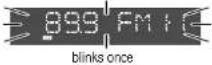
② Auto Preset Memory (APM)
Press and hold [BAND] (APM: auto preset memory) for more than 2 seconds.
- The 6 stations with good reception will be automatically saved in the memory under preset buttons from [1] to [6].
- Once set, the preset stations are sequentially scanned for 5 seconds each.
Manual Preset Memory
① Use manual or seek tuning to find a station. (→ page 10)
② Press and hold one of the preset buttons from [1] to [6] until the display blinks once.
Preset Station Calling
Press the corresponding preset button from [1] to [6] to tune in a preset station.
Caution: To ensure safety, never attempt to preset stations while you are driving.
CQ-RG153U
Cassette Tape Player
① Loading a Cassette
Gantly insert a cassette with the exposed tape side facing to the right until the mechanism captures it, and playback starts.
natural_image
Close-up of a computer control panel with buttons and a central display (no visible text or symbols)Exposed Tape side
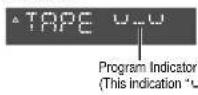
② Play Side Change
Press [◀◀] and [▶▶] at the same time to switch to the program on the other side of the tape. The display changes to indicate which program is playing.

③ Rewind and Fast Forward
When the program indicator ▲ lights, press [◀◀] to rewind or press [▶▶] to fast forward the tape.
When the program indicator ▼ lights. press [◀◀] to fast forward or press [▶▶] to rewind the tape.
blinks

To stop rewind or fast forward, gently press the button that is not in use. The tape will resume playing from that position.
Stop and Eject
Once inserted into the unit, your tape will play continuously until you eject it. If you press [▲] (eject), the unit ejects the tape and returns to radio operation. When you stop the car engine, the tape will stop but not be ejected.
Notes:
- You can not change to CD Changer mode or Radio mode while tape playing. If you want to change to CD Changer mode or Radio mode, eject the tape.
- Always remove the cassette when you stop using the cassette player. This will prolong the life of your tape.
Display Change
Press [DISP] (display) to switch to the clock display.

Tape
CQ-RG153U
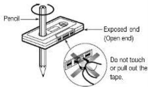
Note: To maintain your cassette player in top condition, avoid using tapes that are longer than 90 minutes (C-90).
Notes on Cassette Tapes
Tape Slack:
Use a pencil or similar object to take up the slack as shown. If a loose tape is used, this may result in the tape becoming tangled in the rotating parts of the unit.
CQ-RG153U
CD Changer Control
①CD Changer mode
While a disc magazine is inserted in the CD changer, press [CD-C]. Play starts from the first track.
Note: The cassette, if loaded, should be removed. Otherwise, the CD play will not start.
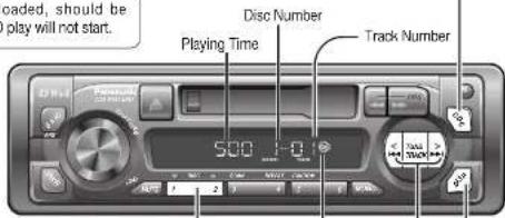
②Disc Selection
[1] (∨ DISC): Previous disc. [2] (∧ DISC): Next disc.
③Track Selection
Press [TRACK ▶▶] once to go to the next track, Press repeatedly to step forward through all the tracks. Press [TRACK ◀◀] once to play from the beginning of the current track, Press twice to play the previous track. Press repeatedly to step backward through all the tracks.
Track Search
Press and hold [TRACK▶▶] or [TRACK▶◀] for more than 0.5 second to activate fast forward or reverse through a track. Release [TRACK▶▶] or [TRACK▶◀] to resume the normal CD play from that position.
Display Change
Press [DISP] (display) to switch to the clock display.

CD Changer
Clock display
CQ-RG153U
Note: CD changer functions are applicable to units with optional CD changer unit (sold separately).
Scan Play (Tracks)
- Press [3] (SCAN). The track number blinks and the first 10 seconds of each track on the discs play in sequence. - Press [3] (SCAN) again to cancel and continue with the current track.

Scan Play (Discs)
- Press and hold [3] (SCAN) for more than 2 seconds. The first track of all the discs in the magazine is played for 10 seconds each and Disc Number blinks. - Press and hold[3] (SCAN) for more than 2 seconds again to cancel.

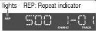
Repeat Play
- Press [4] (REPEAT) to repeat the current selection. - Press [4] (REPEAT) again to cancel.
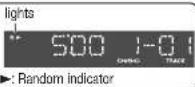
Random Play
- Press [5] (RANDOM) to random selection of music is played from all available CDs. - Press [5] (RANDOM) again to cancel.
Error Display Messages

DISC No.
Disc is dirty, or is upside down. → Select the next available compact disc. Check the disc.

DISC No.
Disc has scratches. → Select the next available compact disc. Check the disc.

No operation by some cause. → Eject the magazine. If failure persists, press the reset switch on the CD changer. If normal operation is not restored yet, call the store where you purchased the unit.

No disc in the changer (magazine) → Insert discs into the changer (magazine).
CQ-RG153U
Troubleshooting
Preliminary Steps
Check and take steps as described in the tables below.
If You Suspect Something Wrong
Immediately switch the power off.
Disconnect the power connector and check that there is neither smoke nor heat from the unit before asking for repairs. Never try to repair the unit by yourself because it is dangerous to do so.
Cautions:
- Do not use the unit if it malfunctions or if there is something wrong.
- Do not use the unit in irregular condition, for example, without sound, or with smoke or foul smell, which can cause ignition or electric shock. Immediately stop using it and call the store where you purchased it.
Troubleshooting Tips
Common
Trouble
Cause/Step
No power.
Car's ignition switch is not on. →Turn your car's ignition switch to ACC or ON.
Cables are not correctly connected.
→Connect cables correctly.
Battery cable is not correctly connected.
→Connect the battery cable to the terminal that is always active.
Accessory cable is not correctly connected.
→Connect the accessory cable to your car's ACC source.
Grounding wire is not correctly connected.
→Connect the grounding wire to a metal part of the car.
Fuse is burnt.
→Consult the store where you purchased the unit, and ask for fuse replacement.
Mute is set to ON.
→Set it to OFF.
Cables are not correctly connected.
→Connect cables correctly.
The ground lead is not connected properly.
→Connect the ground lead properly.
Radio
Trouble
Much noise in FM stereo and monaural broadcasts.
Preset station is reset.
Cause/Step
The antenna ground lead is not connected properly. →Connect the antenna ground lead properly.
The radio antenna is not extended enough. → Extend fully the radio antenna.
Battery cable is not correctly connected. →Connect the battery cable to the terminal that is always active.
□ Cassette Tape
Trouble
No sound.
Tape sound quality is poor.
Reproduction of high tones is poor.
Wow and flutter level is very high.
Cause/Step
Blank tape is inserted in the unit. →Insert recorded tape into the unit.
Heads are dirty. →Clean heads. (Ask a service representative for advice.)
Poor quality tape. →Use better quality tape.
Heads are magnetized. →Demagnetize heads. (Ask a service representative for advice.)
Tape running mechanism is dirty or out of order. →Clean tape running mechanism, or repair it. (Ask a service representative for advice.)
Sound Setting
Trouble
No sound from left, right, front, or rear speaker.
Left and right sounds are reversed in stereo listening.
Cause/Step
Left and right balance, or front and rear balance is off on one side. →Adjust BAL/FAD as appropriate.
Cables are not correctly connected. →Connect the cables correctly.
The right speaker wire is connected to the left speaker and the left speaker wire to the right speaker. →Connect the speaker wires to the correct one.
Speaker Connections
Caution: Please follow the instructions given below. Failure to do so will cause damage to the unit and speakers.
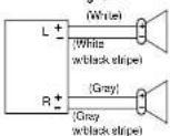
- Use ungrounded speaker only.
- The maximum speaker input should be 45 W or more. (If used with the optional power amplifier, the speaker input should be higher than the maximum amplifier output.)
• The speaker impedance should be 4 - 8 Ω. - This unit uses the BTCL circuit, so each speaker should be connected separately using parallel vinyl insulated cords.
- The speaker cords and the power amplifier unit should be kept away (about 30 cm apart) from the antenna and antenna extension cord.
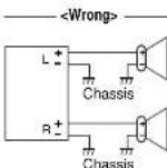
• Never connect the speaker cord to the body of the car.
- Do not use a 3-wire type speaker system having a common earth lead.
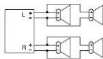
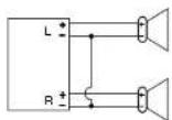
- Do not connect more than one speaker to one set of speaker leads.
Fuse
Use fuses of the same specified rating (15 A). Using different substitutes or fuses with higher ratings, or connecting the unit directly without a fuse, could cause fire or damage to the unit.
If the fuse replacement fails, contact your nearest authorized Panasonic Service Center.
Product Servicing
If the suggestions in the charts do not solve the problem, we recommend that you take it to your nearest authorized Panasonic Servicenter. The product should be serviced only by a qualified technician.
Maintenance
Your product is designed and manufactured to ensure the minimum of maintenance. Use a soft cloth for routine exterior or cleaning. Never use benzine, thinner, or other solvents.
CQ-RG153U
Installation Guide

WARNING
This installation information is designed for experienced installers and is not intended for non-technical individuals. It does not contain warnings or cautions of potential dangers involved in attempting to install this product.
Any attempt to install this product in a motor car by anyone other than qualified installer could cause damage to the electrical system and could result in serious personal injury or death.
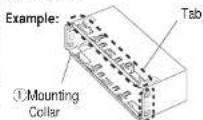
□ Installation Hardware
| No. | Item | Diagram | Q'ty |
| 1 | Mounting collar | 1 | |
| 2 | Hex. nut (5 mmo) | 1 | |
| 3 | Rear support strap | 1 | |
| 4 | Tapping screw(5 mmo · 16 mm) | 1 | |
| 5 | Mounting bolt (5 mmo) | 1 | |
| 6 | Power connector | 1 | |
| 7 | Dismounting plate | 2 | |
| 8 | Trim plate | 1 |
If you encounter problems, please consult your nearest professional installer.
Caution: This unit operates with a 12 V DC negative ground auto battery system only. Do not attempt to use it in any other system. Doing so could cause serious damage.
Before you begin installation, look for the items which are packed with your unit.
- Warranty Card...Fill this out promptly.
- Panasonic Servicenter List for Service Directory ...Keep for future reference in case the product needs servicing.
- Installation Hardware...Needed for in-dash installation.
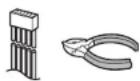
□ Required Tools
You'll need a screwdriver, a 1.5 V AA battery, and the following:
12 V DC
Test bulb
Electrical tape Side-cut
pliers


Overview
This product should be installed by a professional. However, if you plan to install this product yourself, your first step is to decide where to install it. The instructions in these pages will guide you through the remaining steps:
(Please refer to the "WARNING" statement above.)
- Identify and label the car wires.
- Connect the car wires to the wires of the power connector.
• Install the unit in the dashboard. - Check the operation of the unit.
CQ-RG153U
Installation Guide (Continued)
□ Identify All Leads
The first step in installation is to identify all the car wires you'll use when hooking up your sound system.
As you identify each wire, we suggest that you label it using masking tape and a permanent marker. This will help avoid confusion when making connections later.
Note: Do not connect the power connector to the stereo unit until you have made all connections. If there are no plastic caps on the stereo hooking wires, insulate all exposed leads with electrical tape until you are ready to use them. Identify the leads in the following order.
Power Lead
If your car has a radio or is pre-wired for one:
Cut the connector wires one at a time from the plug (leaving the leads as long as possible) so that you can work with individual leads.
Turn the ignition on to the accessory position, and ground one lead of the test bulb to the chassis.
Touch the other lead of the test bulb to each of the exposed wires from the cut radio connector plug. Touch one wire at a time until you find the outlet that causes the test bulb to light.
Now turn the ignition off and then on. If the bulb also turns off and on, that outlet is the car power lead.
If your car is not wired for an audio unit: Go to the fuse block and find the fuse port for radio (RADIO), accessory (ACC), or ignition (IGN).
Battery Lead
If your stereo unit has a yellow lead, you will need to locate the car's battery lead. Otherwise you may ignore this procedure. (The yellow battery lead provides continuous power to maintain a clock, memory storage, or other function.)
If your car has a radio or is pre-wired for one:
With the ignition and headlights off, identify the car battery lead by grounding one lead of the test bulb to the chassis and checking the remaining exposed wires from the cut radio connector plug.
If your car is not wired for an audio unit:
Go to the fuse block and find the fuse port for the battery, usually marked BAT.
Speakers
Identify the car speaker leads. There are two leads for each speaker which are usually color coded.
A handy way to identify the speaker leads and the speaker they are connected with is to test the leads using a 1.5 V AA battery as follows.
Hold one lead against one pole of the battery and stroke the other lead across the other pole. You will hear a scraping sound in one of the speakers if you are holding a speaker lead.
If not, keep testing different lead combinations until you have located all the speaker leads. When you label them, include the speaker location for each.
Antenna
The antenna lead is a thick, black wire with a metal plug at the end.
□ Connect All Leads
Now that you have identified all the wires in the car, you are ready to begin connecting them to the stereo unit wires. The wiring diagram ( page 25) shows the proper connections and color coding of the leads.
We strongly recommend that you test the unit before making a final installation.
You can set the unit on the floor and make temporary connections to test the unit. Use electrical tape to cover all exposed wires.
Important: Connect the red power lead last, after you have made and insulated all other connections.
Ground
Connect the black ground lead of the power connector to the metal car chassis.
CQ-RG153U
Speakers
Connect the speaker wires. See the wiring diagram ( page 25) for the proper hookups. Follow the diagram carefully to avoid damaging the speakers and the stereo unit.
The speakers used must be able to handle more than 45 W of audio power. If using an optional audio amplifier, the speakers should be able to handle the maximum amplifier output power. Speakers with low input ratings can be damaged. Speaker impedance should measure 4–8 Ω, which is typically marked on most speakers. Lower or higher impedance speakers will affect output and can cause both speaker and stereo unit damage.
Battery
Connect the yellow battery lead to the correct radio wire or to the battery fuse port on the fuse block.
Antenna
Connect the antenna by plugging the antenna lead into the antenna receptacle.
Equipment
Connect any optional equipment such as an amplifier, according to the instructions furnished with the equipment. Leave about 12' (30 cm) of distance between the speaker leads/amplifier unit and the antenna/antenna extension cord. Read the operating and installation instructions of any equipment you will connect to this unit.
Power
Connect the red power lead to the correct car radio wire or to the appropriate fuse port on the fuse block.
If the stereo unit functions properly with all these connections made, disconnect the wires and proceed to the final installation.
Final Installation
Lead Connections
Connect all wires, making sure that each connection is insulated and secure. Bundle all loose wires and fasten them with tape so they will not fall down later. Now insert the stereo unit into the mounting collar.
Congratulations! After making a few final checks, you're ready to enjoy your new auto stereo system.
Final Checks
-
Make sure that all wires are properly connected and insulated.
-
Make sure that the stereo unit is securely held in the mounting collar.
-
Turn on the ignition to check the unit for proper operation.
If you have difficulties, consult your nearest authorized professional installer for assistance.
□ Preparation
• We strongly recommend that you wear gloves for installation work to protect yourself from injuries.
- When bending the mounting tabs of the mounting collar with a screwdriver, be careful not to injure your hands and fingers.
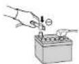
- Disconnect the cable from the negative battery terminal (see cautions below).
- Unit should be installed in a horizontal position with the front end up at a convenient angle, but not more
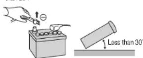
Caution: Do not disconnect the battery terminals of a car with a trip or navigational computer since all user settings stored in memory will be lost. Instead take extra care with installing the unit to prevent shorts.
Dashboard Installation
Installation Opening
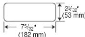
This unit can be installed in any dashboard having an opening as shown above. The dashboard should be 12 (4.75 mm)– 12 (5.66 mm) thick in order to be able to support the unit.
CQ-RG153U
Installation Guide (Continued)
Cautions:
• We strongly recommend that you wear gloves for installation work to protect yourself from injuries.
- When bending the mounting tab of the mounting collar with a screwdriver, be careful not to injure your hands and fingers.
First complete the electrical connections, and then check them for correctness. (→page 25)
The included Mounting Collar ① is designed specially for this unit. Do not use it to attach any other model.
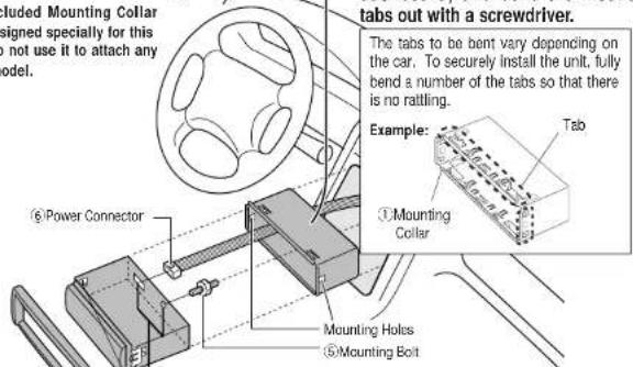
[NO TEXT]
Insert Mounting Collar ① into the dashboard, and bend the mounting tabs out with a screwdriver.
The tabs to be bent vary depending on the car. To securely install the unit, fully bend a number of the tabs so that there is no rattling.
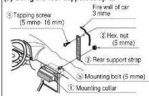
2
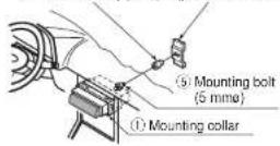
Establish the rear connection of the unit. After fixing Mounting Bolt ⑤ and Power Connector ⑥, fix the rear of the unit to the car body by either method (a) or (b) shown below.
3
Insert Trim Plate ⑧.
4
After installation reconnect the negative (-) battery terminal.
Engage the both sides Mounting Springs (※) in the mounting holes of the Mounting Collar
① firmly.

Mounting Spring
(a) Using the rear support strap ③
(b) Using the rubber cushion (option)
Rubber cushion (option) Rear support bracket (provided on the car)
CQ-RG153U
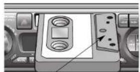
☐ To Remove the Unit
Switch off the power of the unit.

Remove the removable face plate.
① Press [↑] . (release button). The removable face plate will be released.
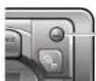
Release button
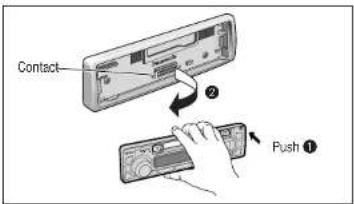

Remove the Trim Plate ⑧ with a screwdriver.
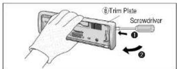

Insert the Dismounting Plates ⑦ along the grooves on both sides of the main unit until "click" is heard.
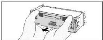
② Pull out the unit while pushing the plates further inside.
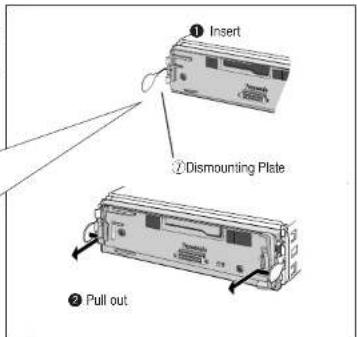

Remove the unit pulling with both hands.
natural_image
Illustration of hands holding a device with an arrow pointing to a component (no text or symbols visible)CQ-RG153U
Anti-Theft System
This unit is equipped with a removable face plate. Removing this face plate makes the radio totally inoperable.
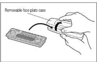
Place the Removable Face
Plate into Case
① Switch off the power of the unit.
② Remove the removable face plate. (→ page 23)
③ Gently press the bottom of the case and open the cover. Place the face plate into the case and take it with you when you leave the car.
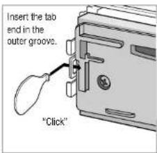
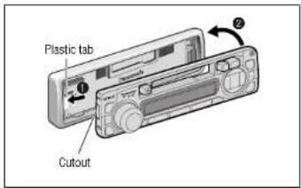
Install Removable Face Plate
① Slide the left side of the removable face plate in place.
② Press the right end of the removable face plate until "click" is heard.
Cautions:
- This face plate is not waterproof. Do not expose it to water or excessive moisture.
- Do not remove the face plate while driving your car.
- Do not place the face plate on the dashboard or nearby areas where the temperature rises to high level.
- Do not touch the contacts on the face plate or the main unit, since this may result in poor electrical contacts.
- If dirt or other foreign substances get on the contacts, wipe them off with a clean and dry cloth.
CQ-RG153U
Electrical Connections
Preparation:
- This unit can be connected to an optional CD changer (CX-DP88U). For details consult your nearest Panasonic Servicenter.
- For connection to a CD changer, refer to the operating instructions of the CD Changer (CX-DP88U).
Cautions:
- This product is designed to operate with a 12 V DC, negative ground battery system.
• To prevent damage to the unit, be sure to follow the connection diagram below - Strip about 5mm of the lead ends for connection
- Do not insert the power connector into the unit until the wiring is completed.
- Be sure to insulate any exposed wires from a possible short-circuit from the car chassis. Bundle all cables and keep cable terminals free from touching any metal parts.
- Remember, if your car has a drive computer or a navigation computer, the data of its memory may be erased when the battery terminals are disconnected.
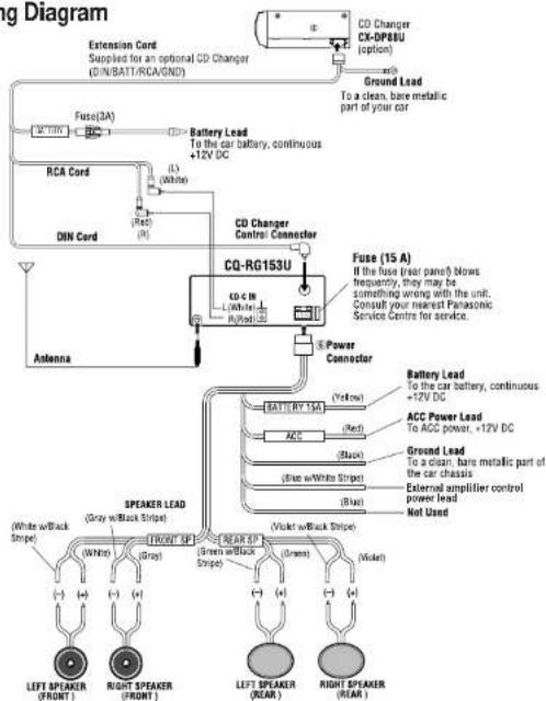
□ Wiring Diagram
flowchart
graph TD
    A["CD Changer CX-DP86U (option)"] --> B["Ground Lead To a clean, bare metallic part of your car"]
    B --> C["Fuse(3A)"]
    C --> D["Battery Lead To the car battery, continuous +12V DC"]
    D --> E["RCA Cord"]
    E --> F["DIN Cord"]
    F --> G["CQ-RG153U"]
    G --> H["CD Changer Control Connector"]
    H --> I["Power Connector"]
    I --> J["Speaker Lead"]
    J --> K["LEFT SPEAKER (FRONT)"]
    J --> L["RIGHT SPEAKER (FRONT)"]
    J --> M["LEFT SPEAKER (REAR)"]
    J --> N["RIGHT SPEAKER (REAR)"]
    J --> O["Ground Lead To a clean, bare metallic part of the car chassis"]
    J --> P["External amplifier control power lead Not Used"]
    J --> Q["Battery Lead To the car battery, continuous +12V DC"]
    J --> R["ACC Power Lead To ACC power, +12V DC"]
    J --> S["Ground Lead To a clean, bare metallic part of the car chassis"]
    J --> T["Power Amplifier Control power lead Not Used"]
CQ-RG153U
Specifications
□ General
Power Supply : 12 V DC (11 V-16V) test Voltage 14.4 V, Negative ground
Current consumption: Less than 2.5 A (tape mode, 0.5 W 4-speaker)
Maximum Power Output : 45 W · 4 channels at 400 Hz, Volume Control maximum
Tone adjustment range : Bass; ± 12 dB at 100 Hz
Treble: ± 12 dB at 10 kHz
Pre-Amp Output Voltage : 2.0 V (CD Play mode; 1 kHz 0 dB)
Suitable Speaker Impedance
:4 Ω (4-8 Ω acceptable)
Dimensions (W - H - D)
50 dB Quieting Sensitivity
: 17 dBf. (1.8 μV/75W)
Frequency Response
: 30-15 000 Hz ±3 dB
Alternate Channel Selectivity
: 75 dB
Stereo Separation
: 35 dB at 1 kHz
Signal/Noise Ratio
: 70 dB (Mono)
□ AM Radio
Frequency range:
: 530 kHz–1710 kHz
Usable sensitivity
: 28 dB/μV (25μV, S/N 20 dB)
□ Tape Player
Reproduction System
: 4-track, 2-program stereo
Tape Speed
: 1-7/8*/sec (4.76 cm/sec)
FF/REW Time
: Less than 200 sec (C-60)
Frequency Response
: 35-14 000 Hz ±3 dB
Wow and Flutter
- 0.12% (WRMS)
signal/Noise Ratio
: 52 dB
Above specifications comply with EIA standards.
Note: Specifications and design are subject to modification without notice due to improvements in technology.
CQ-RG153U
natural_image
Close-up of a computer control panel with buttons and a central display (no visible text or symbols)natural_image
Illustration of hands holding a device with an arrow indicating rotation (no text or symbols)CQ-RG153U
Système antivol

natural_image
Close-up of a computer control panel with buttons and a central display (no visible text or symbols)[1] (√ DISC): Disco anterior.
[2] (∧DISC): Disco siguiente
natural_image
Illustration of hands holding a rectangular electronic device with an arrow indicating rotation (no text or symbols)CQ-RG153U
Sistema antirrobo
Panasonic Consumer Electronics Company, Division of Mitsubishi
Company, Division of Matsushit, Electric Corporation of America
One Panasonic Way, Secaucus,
New Jersey 07094
http://www.panasonic.com
Panasonic Sales Company.
Division of Matsushita Electric of Puerto Rico, Inc. ("BSC")
Puerto Rico, Inc. ( PSC )
Ave. 65 de Infanteria, Km. 9.5
San Gabriel Industrial Park, Carolina, Puerto Rico 00095
Puerto Rico dosas
http://www.panasonic.com
Panasonic Canada Inc.
5770 Ambler Drive, Mississauga, Ontario
L4W 2T3
www.panasonic.ca