
FSG 85 B1 - Garden shredder FLORABEST - Free user manual and instructions
Find the device manual for free FSG 85 B1 FLORABEST in PDF.
| Device type | Chain sharpener |
| Brand | Florabest |
| Model | FSG 85 B1 |
| Input voltage | 230 V~, 50 Hz |
| Power consumption | 85 W (S2: 15 min) |
| No-load speed | 5000 min⁻¹ |
| Grinding wheel dimensions | Ø ext. 104 mm, Ø hole 22 mm, thickness 3.2 mm |
| Weight | approx. 2.6 kg |
| Adjustment angle | -35° to +35° |
| Compatible chain types | Pitch 6.35 / 8.255 / 9.52 mm (1/4", 0.325", 3/8") |
| Protection class | II |
| Sound pressure level | 83 dB(A) |
| Sound power level | 96 dB(A) (guaranteed 99 dB(A)) |
| Vibration | 3.05 m/s² |
| Main functions | Sharpening chainsaw chains, thermal protection, restart protection |
| Maintenance and cleaning | Regular cleaning of ventilation slots and guide rail; replace grinding wheel if worn; store in a dry place |
| Safety | Eye protection shield, emergency stop, disconnect before maintenance, avoid contact with rotating grinding wheel |
| Spare parts and repairability | Grinding wheel cover (91102832), handle (91102833), chain clamping device (91102830), grinding wheel (30211030), nut and hub (91102831); 3-year warranty |
| General information | Domestic use, short-term operation (15 min max, 5 min break), IAN 109774 |
Frequently Asked Questions - FSG 85 B1 FLORABEST
User questions about FSG 85 B1 FLORABEST
0 question about this device. Answer the ones you know or ask your own.
Ask a new question about this device
Download the instructions for your Garden shredder in PDF format for free! Find your manual FSG 85 B1 - FLORABEST and take your electronic device back in hand. On this page are published all the documents necessary for the use of your device. FSG 85 B1 by FLORABEST.
USER MANUAL FSG 85 B1 FLORABEST
Translation of the original instructions
DE AT CH
KETTENSCHÄRFGERÄT
Before reading, unfold the page containing the illustrations and familiarise yourself with all functions of the device.
GB Translation of the original instructions Page
34
A
B
C
Sommaire
Introduction 4
Fin d'utilisation 5
Chere cliente, cher client,
General description. 35
Scope of delivery. 35
Function description. 35
Summary 35
Technical specifications. 36
Safety Instructions. 37
Safety instructions/symbols on the equipment. 37
Symbols in the manual. 37
General safety instructions 37
Further Safety Instructions 39
Installation. 40
Operation 40
Working with the equipment. 40
Switching on and off 41
Sharpening the saw chain 41
Maintenance and cleaning ....43
Cleaning. 43
Changing the grinding disk. 43
Storage. 44
Waste disposal and environmental protection .44
Replacement parts/accessories...44
Guarantee 45
Repair Service. 46
Service-Center 46
Importer 46
Translation of the original EC declaration of conformity ....47
Exploded Drawing 49
Introduction
Congratulations on the purchase of your new device. With it, you have chosen a high quality product.
During production, this equipment has been checked for quality and subjected to a final inspection. The functionality of your equipment is therefore guaranteed. It cannot be ruled out that residual quantities of water or lubricants will remain on or in the equipment/hose lines in isolated cases. This is not a fault or defect and it represents no cause for concern.

The operating instructions constitute part of this product. They contain important information on safety, use and disposal.
Before using the product, familiarise yourself with all of the operating and safety instructions. Use the product only as described and for the applications specified.
Keep this manual safely and in the event that the product is passed on, hand over all documents to the third party.
Intended use
The chain sharpener is suitable for sharpening the standard saw chain types.
The equipment is not designed for any other type of application (e.g. grinding with a coolant liquid, grinding other work pieces or materials such as asbestos, which are hazardous to health).
The equipment is intended for use in the field of DIY. It is not designed for commercial use.
The equipment is designed for use by adults. Young people under the age of 16
are permitted to use the equipment only under supervision.
The manufacturer shall not be liable for damages caused by use other than for the intended purpose or by incorrect operation.
General description
The illustrations can be found on the front and rear fold-out pages.
Scope of delivery
Unpack the equipment and check that it is complete. Dispose of the packaging material correctly.
- Chain sharpener with grinding disk installed
- Handle
- Chain clamping unit and locking screw
- Adjusting screw and washer
- Two screws, nuts and washers for mounting on the worktop
- Instruction Manual
Function description
Prior to first starting the appliance, firmly mount it on a worktop. It is driven by an electric motor with protection against overheating and restart for added safety.
The rake angle is easily adjustable between -35^ and +35^ using a rotary disk. The chain guide rail has a variably adjustable stopper. To sharpen, swivel the grinding head. The equipment is fitted with a protective screen in order to protect the user.
For the function of the operating parts, please refer to the descriptions below.
Summary

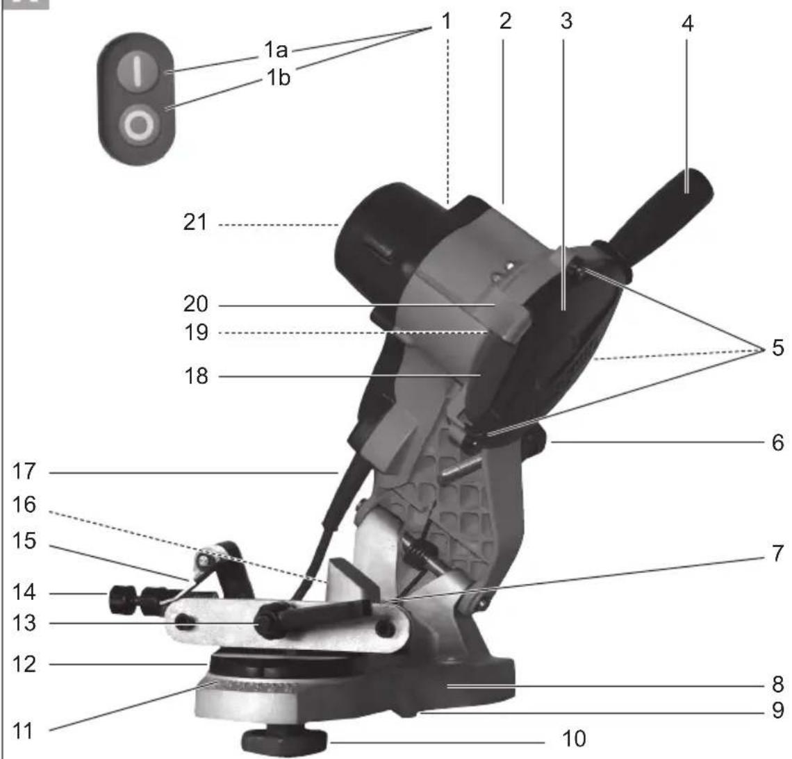
1 On/off switch
On switch
Off switch
2 Grinding head
3 Grinding disk cover
4 Handle
5 Fixing screws for grinding disk cover
6 Adjusting screw and adjusting nut for depth stopper
7 Guide rail
8 Grinding plinth
9 Stop notches
10 Locking screw for chain clamping unit
11 Scale for rake angle (+35^ to -35^)
12 Chain clamping unit and rotary disk
13 Chain tensioning and clamping lever
14 Chain feed adjusting screw and adjusting nut
15 Stopper
16 Cable hook (not shown)
17 Mains cable
18 Grinding disk and grinding disk nut (not shown)
19 LED-lamp (not shown)
20 Protective screen
21 Ventilation openings (not shown)

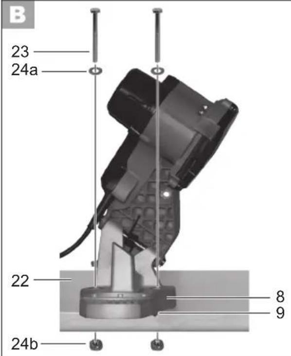
22 Worktop
2 screws (for mounting on the worktop)
24a 2 washers (for mounting on the worktop)
24b 2 nuts (for mounting on the worktop)

25 Washer (for adjusting screw)
Mounting nut (for adjusting screw)

27 Cutting tooth (chain saw)
Depth limiter lug (chain saw)
Technical specifications
Chain sharpener .FSG 85 B1
Nominal input voltage 230 V\~, 50 Hz
Power consumption max. 85 W (S2: 15 min)**
Rated resting period .approx. 5 min
Safety class.
Mechanical rating.. IP 20
Idle-running speed n_0 5000 min-1
Disk speed max. 27.8m / s^
Adjustment angle 35° left / right
For saw chains
with link sizes...6.35/8.255/9.52mm
(1 / 4^ / 0.325^ / 3 / 8^ )
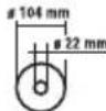
Dimensions grinding disk
external diameter 104 mm
diameter of bore 22 mm
thickness 3.2 mm
Weight (incl. accessories)..approx. 2.6kg
Sound pressure level
(L_PA) 83 dB(A); K_PA = 3 dB
measured. 96 dB(A); K_WA = 3 dB
guaranteed 99 dB(A)
Vibration (a_h) 3.05 m/s², K=1.5 m/s²
- The grinding disk must be able to withstand a circulation speed of minimum 27.8 m/s.
Is the max. rotation speed on the grinding disk too small in contrast to the appliance the grinding disk can break.
** Do not operate the equipment for longer
than 15 minutes without interruption; then take a rest break of 5 minutes.
Technical and optical changes may be undertaken in the course of further development without notice. All dimensions, references and information in this instruction manual are therefore not guaranteed. Legal claims made on the basis of the instruction manual can therefore not be considered as valid.
The stated vibration emission value was measured in accordance with a standard testing procedure and may be used to compare one power tool to another.
The stated vibration emission value may also be used for a preliminary exposure assessment.

Warning:
ibration emission value may
differ during actual use of the power tool from the stated value depending on the manner in which the power tool is used.
Safety precautions aimed at protecting the user should be based on estimated exposure under actual usage conditions (all parts of the operating cycle are to be considered, including, for example, times during which the power tool is turned off and times when the tool is turned on but is running idle).
Safety Instructions

WARNING!
When using power tools, observe the following basic safety measures for the prevention of electric shocks and the risk of injury and fire.
Safety instructions/symbols on the equipment

Warning!

Risk of injury from the rotating tool! Keep hands away.

Risk of electric shock!
nnect from the mains before carrying out maintenance and repair work.

Do not expose the unit to rain.

Read and observe the operating instructions pertaining to the equipment. Also observe the safety instructions for your chainsaw and replacement saw chain.

Risk of injury! Wear ear, eye and hand protection!

Wear breathing protection.

Risk of cuts! cut-resistant gloves.

Never use faulty grinding disks.

safety class II

Do not dispose of electrical equipment in household waste.
Dimensions grinding disk
Symbols in the manual

Warning symbols with information on damage and injury prevention.

Instruction symbols (the instruction is explained at the place of the exclamation mark) with information on preventing damage.

Help symbols with information on improving tool handling.
General safety instructions
- This device can be used by individuals with reduced physical, sensory or mental capabilities or a lack of experience or knowledge if they are supervised or have been instructed in how to use the device safely and understand the associated dangers. Children must not play with the device.
Safe operation:
- Keep work area clear.
Cluttered areas and benches invite injuries.
-
Consider work area environment.
-
Do not expose tools to rain. Do not use tools in damp or wet locations. Water entering a power tool will increase the risk of electric shock.
-
Keep work area well lit.
-
Do not use tools in the presence of flammable liquids or gases. Power tools create sparks which may
ignite the dust or fumes.
- Guard against electric shock.
Avoid body contact with earthed or grounded surfaces (e.g. pipes, radiators, ranges, refrigerators).
- Keep other persons away.
Do not let persons, especially children, not involved in the work touch the tool or the extension cord and keep them away from the work area. - Store idle tools. When not in use, tools should be stored in a dry locked-up place, out of reach of children.
- Do not force the tool. It will do the job better and safer at the rate for which it was intended.
-
Use the right tool.
-
Do not force small tools to do the job of a heavy duty tool.
- Do not use tools for purposes not intended; for example do not use circular saws to cut tree limbs or logs.
Use of the power tool for operations different from those intended could result in a hazardous situation.
-
Dress properly.
-
Do not wear loose clothing or jewellery, they can be caught in moving parts.
- Anti-slip footwear is recommended when working outdoors.
-
Wear protective hair covering to contain long hair.
-
Use protective equipment.
-
Use safety glasses.
-
Use face or dust mask if working operations create dust.
-
Connect dust extraction equipment. If the tool is provided for the connection of dust extraction and collecting equipment, ensure these are connected and properly used.
- Do not abuse the cord. Never yank the cord do disconnect it from the
socket. Keep the cord away from heat, oil and sham edges.
- Secure work. Where possible use clamps or a vice to hold the work. It is safer than using your hand.
-
Do not overreach. Keep proper footing and balance at all times. This enables better control of the power tool in unexpected situations.
-
Maintain tools with care.
Many accidents are caused by poorly maintained power tools.
- Keep cutting tools sharp and clean for better and safer performance.
- Follow instruction for lubricating and changing accessories.
- Inspect tool cords periodically and if damaged have them repaired by an authorized service facility.
- Inspect extension cords periodically and replace if damaged.
-
Keep handles dry, clean and free from oil and grease.
-
Disconnect tools. When not in use, before servicing and when changing accessories disconnect tools from the power supply. Such preventive safety measures reduce the risk of starting the power tool accidentally.
- Remove adjusting keys and wrenches. Form the habit of checking to see that keys and adjusting wrenches are removed from the tool before turning it on. A wrench or a key left attached to a rotating part of the power tool may result in personal injury.
- Avoid unintentional starting. Ensure switch is in "off" position when plugging in.
- Use outdoor extension leads. When the tool is used outdoors, use only extension cords intended for outdoor use and so marked.
- Stay alert, watch what you are
doing and use common sense when operating a power tool.
Do not use a power tool while you are tired or under the influence of drugs, alcohol or medication. A moment of inattention white operating power tools may result in serious personal injury.
-
Check damaged parts. This will ensure that the safety of the power tool is maintained.
-
Before further use of tool, it should be carefully checked to determine that it will operate properly and perform its intended function.
- Check for alignment of moving parts, binding of moving parts, breakage of parts, mounting and any other conditions that may affect its operation.
- A guard or other part that is damaged should be properly repaired or replaced by an authorized service centre unless otherwise indicated in this instruction manual.
- Have defective switches replaced by an authorized service centre.
- Do not use the tool if the switch does not turn it on and off. There is a risk of injury.
- Warning.
The use of any accessory or attachment other than one recommended in this instruction manual may present a risk of personal injury.
- Have your tool repaired by a qualified person. This electric tool complies with the relevant safety rules. Repairs should only be carried out by qualified persons using original spare parts, otherwise this may result in considerable danger to the user.
- If the supply cord of this power tool is damaged, it must be replaced by a specially prepared cord available through the service organization.
Further Safety Instructions
- Connect the device only to a power point with a residual current protective device (RCD) with a measured residual current of not more than 30mA .
- Keep the mains cable and extension cable away from the grinding disk and saw chain. In the event that it is damaged or severed, immediately disconnect the plug from the socket.
Do not touch the cable before it has been disconnected from the mains. Risk of electric shock.
- Before use, carry out a visual inspection of the grinding disk. Do not use grinding disks that are spalled, cracked or otherwise damaged. Replace a worn grinding disk.
- Never operate the device without the visual protection disk.
- Do not work with the device if you are tired or after the consumption of alcohol or tablets. Always take a break from the work in good time.
- Do not use the device in an explosive atmosphere or where sparks could cause fire, explosion etc. Failure to observe this will result in a risk of fire or explosion.
- Keep your hands away from the grinding disk and chain teeth when the device is in use. Do not move the chain by hand. This will cause a risk of injury.
- Never place your fingers between the grinding disk and rotary disk or between the grinding disk and protection disk. This will cause a risk of crushing.
- The chain becomes hot during grinding. Do not touch the machined location, as there is a risk of being burnt.
- Use only grinding disks recommended by the manufacturer. Do not use saw
blades.
-
Switch off the device and disconnect at the plug
-
to release a jammed insertion tool,
- if the connecting cable is damaged or tangled,
- in the case of unusual noises.
Installation

Always use the M10x70 screws from the package to mount the unit.

Make sure to leave enough room for working and that nobody else is put at risk.

Always use screws of sufficient length and thickness to mount the device on the work surface, in order to prevent loss of control of the device.

Installing the appliance:
- Thickness of the table edge: 15 - 30mm
-
Drill diameter: 10.5 mm .
Size of screw: M10 -
Use the stop notches (9) to correctly place the appliance on the worktop (22). Make sure that the grinding plinth (8) protrudes beyond the edge of the table.
- Use a pen to mark the drill holes and remove the appliance.
- Drill two holes into the worktop (22).
- Using the enclosed screws (23), washers and nuts (24), screw the grinding plinth in place on the worktop.

Assembling the grinder:
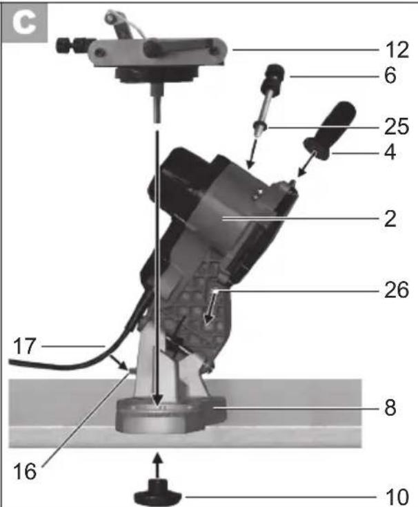
- Screw the handle (4) into the grinding head (2).
- Remove the locking screw (10) from the chain clamping unit (12).
- Place the chain clamping unit (12) on the grinding plinth (8) and fix it using the locking screw (10).
- Snap the mains lead (17) into the cable hook (16).

Screwing on the adjusting rew:
- Place the enclosed washer (25) on the adjusting screw (6).
- Screw the adjusting screw (6) onto the securing nut (26) fixed into the grinding head (2).
Operation
Working with the equipment

Caution! Risk of injury!
- Use only grinding disks and accessories recommended by the manufacturer. The use of other insertion tools and other accessories may cause risk of injury.
- Never operate the device without the visual protection disk.
- Do not use saw blades.
- Check the grinding disk before use: check the distance between the protective screen and the grinding disk.
- Do not use broken, cracked or otherwise damaged grinding disks.
- Switch on the equipment only when it is safely installed on the work surface.

Risk of injury!
Wear ear, eye and hand protection!

When working with the saw chain, wear cut resistant gloves and an apron if necessary, to avoid incision injuries.

Keep hands away from the grinding disk and chain teeth when the equipment is in use. Do not move the chain by hand. There is a risk of injury.

Switching on and off

Ensure that the mains voltage matches the specifications on the rating plate.

Connect the equipment to the mains.
- To switch on, press the "I" On switch (green) and the device starts up (see A 1a).
- To switch off, press the "0" Off switch (red) and the device switches off (see A 1b).

The disk will continue to run after the equipment is switched off. There is a risk of injury.
Protection against overheating and restart:
The unit will not automatically restart following an automatic cutout due to overload. To restart the grinder, press the "I" On switch (green) and the device starts up (see A 1a).
Test run:
Before starting work and after each change of grinding disk, carry out a test
run of at least 30 seconds with no load. Switch off the equipment immediately if the disk runs lumpy, substantial vibrations occur, or abnormal noises are generated.

Sharpening the saw chain

When working with the saw chain, keep clean the ventilation openings (see "Maintenance and cleaning").

In case of a blockage, switch off the equipment and disconnect from the mains. Only then should the blockage be removed.

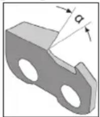
An incorrectly sharpened saw chain may damage the chain the increase the risk of the saw jumping back. Ensure that the chain is aligned accurately.
Observe the correct rake angle and minimum dimensions of the saw chain. Remove as little material as possible.
Do not grind in drive (a) or connecting (b) links, otherwise the saw chain may rupture
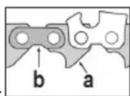
In the event of non-observance, there is a risk of accidents when handling the chainsaw.

Instructions for sharpening
- Clean the saw chain before you sharpen it. Use a brush or cloth to remove oily wood chips or residual oil.
After sharpening, all cutting links must be of equal length and width.
The chain is worn and must be re
placed with a new saw chain if only approx. 4mm of cutting tooth remain.
Inserting the saw chain:
- To open the chain guide, turn the clamping lever (13) anticlockwise. You must first return the clamping lever to its home position several times.
The clamping lever unlocks by pulling it outward, returning it to the home position and allowing it to snap back in.
- Place the saw chain in the chain guide (7). Ensure that the cutting edges face the grinding disk (18).
- Flap down the chain stop (15) and pull the saw chain back until the cutting tooth (27) to be sharpened contacts the stop (see figure D ①).
Adjusting the sharpening angle:
- Loosen the locking screw (10) and use the scale (11) on the rotary disk of the chain clamping unit (12) to set the correct sharpening angle .
Tighten the locking screw.

Adjust the sharpening angle according to the manufacturer's specifications.
Adjusting the stop:
- Turn off the motor and pull down the grinding head (2) by the handle (4).
- Turn the chain feed adjusting screw (14a) to move the cutting tooth (27) towards the grinding disk (18) until they make contact (see figure ②). Tighten the adjusting nut (14b) to lock the adjusting screw (14a).
-
Turn the clamping lever (13) clockwise to tighten the chain links in the chain guide (7) (see 1.).
-
Turn the adjusting screw (6a) to set the depth stopper such that the grinding disk (18) contacts the tooth root (see figure D ②). Tighten the adjusting nut (6b) to set the grinding depth.
Sharpen:
- Switch on the equipment (see "switching on and off").
- By putting gentle pressure on the handle (4), move the grinding head (2) upwards and sharpen the cutting tooth. Do not allow the grinding disk (18) to slow down to stand still. This is prevented by reducing the pressing force early enough.
- Switch off the equipment to move the chain onwards. Loosen the clamping lever (13) and tighten the next chain link to be sharpened in the chain guide (7) using the adjusted chain stop (15) and the clamping lever.

Start by sharpening the teeth on one side of the chain. Then adjust the rake angle and sharpen the teeth on the other side.
Check the depth limiter distance (see image D ③):
The cutting links, which comprise a cutting tooth (27) and a depth limiter lug (28), are the sawing parts of the chain. The height distance between these two is determined by depth limiter distance A.
- After every third sharpening process, check depth limiter distance A against the saw chain manufacturer's specifications.
- Use a flat file to file down the height of the depth limiter lug (28) and, after resetting, round off the depth limiter lug a little. The original shape must remain intact.
Maintenance and cleaning

Disconnect the plug before adjustment, maintenance or repair.

Have any work not described in these instructions carried out by a specialist workshop. Use only original components. Allow the equipment to cool before carrying out any maintenance and cleaning work. There is a risk of burns.
Before each use, check the equipment for obvious defects such as loose, worn or damaged components and check that screws or other parts are sitting correctly. In particular, check the grinding disk (A 18). Replace damaged parts.
Cleaning

Do not use cleaning agents or solvents. Chemical substances may attack plastic parts of the equipment. Never clean the equipment under running water.
- Clean the equipment thoroughly after each use.
Clean the ventilation openings (A 21) and the surface of the equipment with a brush or cloth.
- Clean the guide rail ( A 7) with a brush.
In case of heavy dirt, loosen the locking screw for the chain clamping unit (A 10) and remove the chain clamping unit and rotary disk (A 12) for better access.
We recommended removing the side plates for cleaning.
Changing the grinding disk

Instructions for changing:
Never operate the equipment without the protective screen (A 20).
- Ensure that the rotation speed specified on the grinding disk (A 18) is equal to or greater than the idle-running speed of the appliance. If the max. rotation speed on the grinding disk is too small in contrast to the appliance the grinding disk can break.
Ensure that the disk dimensions fit the equipment.
- Use only fault-free grinding disks (ring test).
- If the locator hole in a grinding disk is too small, do not subsequently redrill in order to increase the size.
- Do not use separated reduction bushes or adapters in order to make a grinding disk fit where the hole is too large.
- Do not use saw blades.
- Reassemble the equipment fully after changing the grinding disk.

Switch off the equipment and disconnect from the mains.
Allow the equipment to cool.

-
Loose the 3 fixing screws (5) and take off the grinding disk cover (3).
-
Remove the grinding disk nut (18b) by hand.
- Take the grinding disk (18a) off the adapter.
- Place a new grinding disk on the adapter and tighten the grinding disk nut by hand.
- Put the grinding disk cover (3) back on.

Do not tighten the grinding disk nut too much because this may cause the grinding disk and nut to break.
- Test run: Before starting work and after each change of grinding disk, carry out a test run of at least 30 seconds with no load. Switch off the equipment immediately if the disk runs lumpy, substantial vibrations occur or abnormal noises are generated.
Storage
- Store the appliance in a dry place well out of reach of children.

Grinding disks must be stored dry and upright and are not to be stacked.
Waste disposal and environmental protection
Be environmentally friendly. Return the tool, accessories and packaging to a recycling centre when you have finished with them.
Machines are not to be place with domestic waste.
Hand over the device at an utilization location. The plastic and metal parts employed can be separated out into pure materials and recycling can be implemented. Ask your Service Center about this. Defective units returned to us will be disposed of for free.
Replacement parts/accessories
Spare parts and accessories can be obtained at www.grizzly-service.eu
If you do not have internet access, please contact the Service Centre via telephone (see "Service-Center" page 46). Please have the order number mentioned below ready.
| Position Instruction manual | Position Exploded drawing | Description number | Order | |
| A3 Set 3 | Grinding disk cover | 91102832 | ||
| A4 Set 4 | Handle with screw 91102833 | |||
| A12 Set 1 | Chain clamping unit and rotary disk 91102830 | |||
| E 18a 33 | Grinding disk | 30211030 | ||
| E 18b/18c | Set 2 Grinding disk nut and hub 91102831 |
Guarantee
Dear Customer, this equipment is provided with a 3-year guarantee from the date of purchase. In case of defects, you have statutory rights against the seller of the product. These statutory rights are not restricted by our guarantee presented below.
Terms of Guarantee
The term of the guarantee begins on the date of purchase. Please retain the original receipt. This document is required as proof of purchase.
If a material or manufacturing defect occurs within three years of the date of purchase of this product, we will repair or replace - at our choice - the product for you free of charge. This guarantee requires the defective equipment and proof of purchase to be presented within the three-year period with a brief written description of what constitutes the defect and when it occurred.
If the defect is covered by our guarantee, you will receive either the repaired product or a new product. No new guarantee period begins on repair or replacement of the product.
Guarantee Period and Statutory Claims for Defects
The guarantee period is not extended by the guarantee service. This also applies for replaced or repaired parts. Any damages and defects already present at the time of purchase must be reported immediately after unpacking. Repairs arising after expiry of the guarantee period are chargeable.
Guarantee Cover
The equipment has been carefully produced in accordance with strict quality guidelines and conscientiously checked prior to delivery. The guarantee applies for all material and
manufacturing defects. This guarantee does not extend to cover product parts that are subject to normal wear and may therefore be considered as wearing parts (e.g. grinding disks, carbon brushes, stopper, protective screen.) or to cover damage to breakable parts (e.g. switches, batteries, or parts made of glass).
This guarantee shall be invalid if the product has been damaged, used incorrectly or not maintained. Precise adherence to all of the instructions specified in the operating manual is required for proper use of the product. Intended uses and actions against which the operating manual advises or warns must be categorically avoided.
The product is designed only for private and not commercial use. The guarantee will be invalidated in case of misuse or improper handling, use of force, or interventions not undertaken by our authorised service branch.
Processing in Case of Guarantee
To ensure quick handling of you issue, please follow the following directions:
- Please have the receipt and identification number (IAN 109774) ready as proof of purchase for all enquiries.
- Please find the item number on the rating plate.
- Should functional errors or other defects occur, please initially contact the service department specified below by telephone or by e-mail. You will then receive further information on the processing of your complaint.
- After consultation with our customer service, a product recorded as defective can be sent postage paid to the service address communicated to you, with the proof of purchase (receipt) and specification of what constitutes the defect and when it occurred. In order to avoid
acceptance problems and additional costs, please be sure to use only the address communicated to you. Ensure that the consignment is not sent carriage forward or by bulky goods, express or other special freight. Please send the equipment inc. all accessories supplied at the time of purchase and ensure adequate, safe transport packaging.
Repair Service
For a charge, repairs not covered by the guarantee can be carried out by our service branch, which will be happy to issue a cost estimate for you. We can handle only equipment that has been sent with adequate packaging and postage.
Attention: Please send your equipment to our service branch in clean condition and with an indication of the defect.
Equipment sent carriage forward or by bulky goods, express or other special freight will not be accepted.
We will dispose of your defective devices free of charge when you send them to us.
Service-Center
Service Great Britain
Tel.: 0871 5000 720 (£ 0.10/Min.)
E-Mail: grizzly@lidl.co.uk
IAN 109774
Importer
Please note that the following address is not a service address. Please initially contact the service centre specified above.

- Sommaire
- Introduction
- Intended use
- General description
- Scope of delivery
- Function description
- Summary
- Technical specifications
- Chain sharpener .FSG 85 B1
- Warning:
- Safety Instructions
- Safety instructions/symbols on the equipment
- Symbols in the manual
- Warning symbols with information on damage and injury prevention.
- General safety instructions
- Safe operation:
- doing and use common sense when operating a power tool.
- - Warning.
- Further Safety Instructions
- Installation
- Installing the appliance:
- Assembling the grinder:
- Screwing on the adjusting rew:
- Operation
- Working with the equipment
- Caution! Risk of injury!
- Switching on and off
- Protection against overheating and restart:
- Test run:
- Sharpening the saw chain
- Instructions for sharpening
- Inserting the saw chain:
- Adjusting the sharpening angle:
- Adjusting the stop:
- Sharpen:
- Check the depth limiter distance (see image D ③):
- Maintenance and cleaning
- Cleaning
- Changing the grinding disk
- Instructions for changing:
- Storage
- Waste disposal and environmental protection
- Replacement parts/accessories
- Guarantee
- Terms of Guarantee
- Guarantee Period and Statutory Claims for Defects
- Guarantee Cover
- Processing in Case of Guarantee
- Repair Service
- Service-Center
- Service Great Britain
- Importer
Brand : FLORABEST
Model : FSG 85 B1
Category : Garden shredder